
Installation Instructions
Page 3
...ĆSide 6 Individual appliances with partition 6 At the end of the kitchen units 6 Installation location 7 Installation room 7 Installation cavity 7 Furniture/fixtures 7 Base 7 Connecting the power 8 Additional grounding procedure 8 Grounding instruction 8 Connecting the water 8 Installation dimensions 9 Single installation 9 SideĆbyĆSide installation 10 Water connection 11 Appliance dimensions 12 1. 18" Appliance (Freezer/Freezer with Ice...
...ĆSide 6 Individual appliances with partition 6 At the end of the kitchen units 6 Installation location 7 Installation room 7 Installation cavity 7 Furniture/fixtures 7 Base 7 Connecting the power 8 Additional grounding procedure 8 Grounding instruction 8 Connecting the water 8 Installation dimensions 9 Single installation 9 SideĆbyĆSide installation 10 Water connection 11 Appliance dimensions 12 1. 18" Appliance (Freezer/Freezer with Ice...

Installation Instructions
Page 4
...36 24. Attaching the covers 37 26. Mounting of the cavity 27 14. Attaching the edge protection 25 10.SideĆbyĆSide installation 25 11. Attaching the adjusting rail to the appliance 28 16. Connecting the water to the furniture door 32 21. Attaching the cover frame... and the shelf 39 28. Installing and aligning the appliance 26 13. Loading the appliance door 32 20. Attaching the furniture door 34 23. Attaching the finger guard 36 25....
...36 24. Attaching the covers 37 26. Mounting of the cavity 27 14. Attaching the edge protection 25 10.SideĆbyĆSide installation 25 11. Attaching the adjusting rail to the appliance 28 16. Connecting the water to the furniture door 32 21. Attaching the cover frame... and the shelf 39 28. Installing and aligning the appliance 26 13. Loading the appliance door 32 20. Attaching the furniture door 34 23. Attaching the finger guard 36 25....

Installation Instructions
Page 5
... or damage may occur as a result of complying with all governing codes and ordinances. Before starting the installation, always read thoroughly, the installation will be properly grounded. e CAUTION Skill - i This symbol is not covered under the Appliance Warranty..... Keep doors closed until the appliance is the responsibility of tipping forward. Level ć Installation of a local code: - Proper installation is completely installed and secured per installation instructions. See the Owner's Manual for its intended purpose. e WARNING Use this appliance requires...
... or damage may occur as a result of complying with all governing codes and ordinances. Before starting the installation, always read thoroughly, the installation will be properly grounded. e CAUTION Skill - i This symbol is not covered under the Appliance Warranty..... Keep doors closed until the appliance is the responsibility of tipping forward. Level ć Installation of a local code: - Proper installation is completely installed and secured per installation instructions. See the Owner's Manual for its intended purpose. e WARNING Use this appliance requires...
Installation Instructions
Page 6
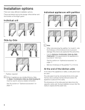
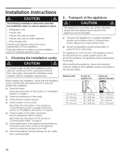
...262;Side * * * Partition required! The side panel must be connected firmly to prevent damage if the doors are many different installation options. Minimum thickness of the side panel are limited only by ĆSide Sealing kit must be used . See the section... on Optional accessories" on page 17. 3. 4. During installation ensure that the cavity is placed in the cavity. The dimensions of the partition 5/8" (16 mm). Individual unit Individual appliances with partition 1....
...262;Side * * * Partition required! The side panel must be connected firmly to prevent damage if the doors are many different installation options. Minimum thickness of the side panel are limited only by ĆSide Sealing kit must be used . See the section... on Optional accessories" on page 17. 3. 4. During installation ensure that the cavity is placed in the cavity. The dimensions of the partition 5/8" (16 mm). Individual unit Individual appliances with partition 1....
Installation Instructions
Page 7
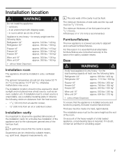
... 950 lbs / 425 kg* Wine unit 18" Wine unit 24" approx. 550 lbs / 245 kg approx. 694 lbs / 310 kg (* without Water Dispenser) Installation room The appliance should not drop below 55 °F (13 °C) or rise above 110 °F (43 °C), otherwise malfunctions may occur. spirit level, ...appliance is essential that the cavity is required. On account of the heavy weight of the furniture front. in a dry, ventilated room. If installation next to a heat source is screwed securely to direct sunlight and not placed near a heat source, such as the rest of toe kick panel...
... 950 lbs / 425 kg* Wine unit 18" Wine unit 24" approx. 550 lbs / 245 kg approx. 694 lbs / 310 kg (* without Water Dispenser) Installation room The appliance should not drop below 55 °F (13 °C) or rise above 110 °F (43 °C), otherwise malfunctions may occur. spirit level, ...appliance is essential that the cavity is required. On account of the heavy weight of the furniture front. in a dry, ventilated room. If installation next to a heat source is screwed securely to direct sunlight and not placed near a heat source, such as the rest of toe kick panel...
Installation Instructions
Page 8
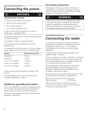
...power supply cord, UL listed in this coherence the following table: Appliance Refrigerator24" Refrigerator 30" Freezer 18" (incl. The receptacle must be installed for the water connection must comply with a 10A fuse or higher. IceMaker) Freezer 30" (incl. Some local regulations may result in a... suitable, easily accessible location. The water pressure must be installed by providing a path of the water pipe (without fittings): 13/32" (10 mm). A separate shutĆoff valve for the appliance ...
...power supply cord, UL listed in this coherence the following table: Appliance Refrigerator24" Refrigerator 30" Freezer 18" (incl. The receptacle must be installed for the water connection must comply with a 10A fuse or higher. IceMaker) Freezer 30" (incl. Some local regulations may result in a... suitable, easily accessible location. The water pressure must be installed by providing a path of the water pipe (without fittings): 13/32" (10 mm). A separate shutĆoff valve for the appliance ...

Installation Instructions
Page 9
Side wall of niche, depending on kitchen design (see DESIGN GUIDE) D = 24" (610 mm) minimum NOTE: Cavity must be suare. Legend: A Area for installation of the water connection B Area for installation of the power connection D Opening depth of the cavity must be flush. Appliance 18" 24" 30" X 18" (457 mm) 24 (610 mm) 30" (762 mm) Y 9" (229 mm) 12" (305 mm) 15" (381 mm) 9 Single installation6. Installation dimensions5.
Side wall of niche, depending on kitchen design (see DESIGN GUIDE) D = 24" (610 mm) minimum NOTE: Cavity must be suare. Legend: A Area for installation of the water connection B Area for installation of the power connection D Opening depth of the cavity must be flush. Appliance 18" 24" 30" X 18" (457 mm) 24 (610 mm) 30" (762 mm) Y 9" (229 mm) 12" (305 mm) 15" (381 mm) 9 Single installation6. Installation dimensions5.

Installation Instructions
Page 10
... above for the two appliances. Side wall of two appliances. Example: Freezer 18" / Refrigerator 30" Legend: A Area for installation of the water connection B Area for installation of the power connection 10 D Opening depth of the cavity widths indicated for the respective appliance apply to a SideĆby&#...262;Side installation of the cavity must be flush. The total width of the cavity results from the addition of niche, depending on kitchen design (see...
... above for the two appliances. Side wall of two appliances. Example: Freezer 18" / Refrigerator 30" Legend: A Area for installation of the water connection B Area for installation of the power connection 10 D Opening depth of the cavity widths indicated for the respective appliance apply to a SideĆby&#...262;Side installation of the cavity must be flush. The total width of the cavity results from the addition of niche, depending on kitchen design (see...

Installation Instructions
Page 12
d) This dimension may vary. For further information about the different styles check the DESIGN GUIDE. c) Thickness of door panel may vary depending on installation, panel thickness and kitchen hardware. 12 e) Unit dimensions Note: One design of the wooden panel displayed. b) Dimensions may vary. Appliance dimensions7. 1. 18" Appliance (Freezer/Freezer with Ice and Water dispenser) e) e) Front view (without door panel) Legend: a) Adjustment in levelling legs +13/8" (35 mm) / -1/2" (13 mm).
d) This dimension may vary. For further information about the different styles check the DESIGN GUIDE. c) Thickness of door panel may vary depending on installation, panel thickness and kitchen hardware. 12 e) Unit dimensions Note: One design of the wooden panel displayed. b) Dimensions may vary. Appliance dimensions7. 1. 18" Appliance (Freezer/Freezer with Ice and Water dispenser) e) e) Front view (without door panel) Legend: a) Adjustment in levelling legs +13/8" (35 mm) / -1/2" (13 mm).

Installation Instructions
Page 13
c) Thickness of the wooden panel displayed. d) This dimension may vary. For further information about the different styles check the DESIGN GUIDE. 13 e) Unit dimensions Note: One design of door panel may vary depending on installation, panel thickness and kitchen hardware. 2. 18" Appliance (Wine unit) e) e) Front view (without door panel) Legend: a) Adjustment in levelling legs +13/8" (35 mm) / -1/2" (13 mm). b) Dimensions may vary.
c) Thickness of the wooden panel displayed. d) This dimension may vary. For further information about the different styles check the DESIGN GUIDE. 13 e) Unit dimensions Note: One design of door panel may vary depending on installation, panel thickness and kitchen hardware. 2. 18" Appliance (Wine unit) e) e) Front view (without door panel) Legend: a) Adjustment in levelling legs +13/8" (35 mm) / -1/2" (13 mm). b) Dimensions may vary.

Installation Instructions
Page 14
b) Dimensions may vary. c) Thickness of the wooden panel displayed. e) Unit dimensions 14 Note: One design of door panel may vary. d) This dimension may vary depending on installation, panel thickness and kitchen hardware. For further information about the different styles check the DESIGN GUIDE. 3. 24" Appliance (Refrigerator/Freezer/Freezer with Ice and Water dispenser) e) e) Front view (without door panel) Legend: a) Adjustment in levelling legs +13/8" (35 mm) / -1/2" (13 mm).
b) Dimensions may vary. c) Thickness of the wooden panel displayed. e) Unit dimensions 14 Note: One design of door panel may vary. d) This dimension may vary depending on installation, panel thickness and kitchen hardware. For further information about the different styles check the DESIGN GUIDE. 3. 24" Appliance (Refrigerator/Freezer/Freezer with Ice and Water dispenser) e) e) Front view (without door panel) Legend: a) Adjustment in levelling legs +13/8" (35 mm) / -1/2" (13 mm).

Installation Instructions
Page 15
e) Unit dimensions Note: One design of door panel may vary. d) This dimension may vary. b) Dimensions may vary depending on installation, panel thickness and kitchen hardware. 4. 24" Appliance (Wine unit) e) e) Front view (without door panel) Legend: a) Adjustment in levelling legs +13/8" (35 mm) / -1/2" (13 mm). For further information about the different styles check the DESIGN GUIDE. 15 c) Thickness of the wooden panel displayed.
e) Unit dimensions Note: One design of door panel may vary. d) This dimension may vary. b) Dimensions may vary depending on installation, panel thickness and kitchen hardware. 4. 24" Appliance (Wine unit) e) e) Front view (without door panel) Legend: a) Adjustment in levelling legs +13/8" (35 mm) / -1/2" (13 mm). For further information about the different styles check the DESIGN GUIDE. 15 c) Thickness of the wooden panel displayed.

Installation Instructions
Page 16
d) This dimension may vary. e) Unit dimensions 16 Note: One design of door panel may vary. For further information about the different styles check the DESIGN GUIDE. c) Thickness of the wooden panel displayed. 5. 30" Appliance (Refrigerator/Freezer/Freezer with Ice and Water dispenser) e) e) Front view (without door panel) Legend: a) Adjustment in levelling legs +13/8" (35 mm) / -1/2" (13 mm). b) Dimensions may vary depending on installation, panel thickness and kitchen hardware.
d) This dimension may vary. e) Unit dimensions 16 Note: One design of door panel may vary. For further information about the different styles check the DESIGN GUIDE. c) Thickness of the wooden panel displayed. 5. 30" Appliance (Refrigerator/Freezer/Freezer with Ice and Water dispenser) e) e) Front view (without door panel) Legend: a) Adjustment in levelling legs +13/8" (35 mm) / -1/2" (13 mm). b) Dimensions may vary depending on installation, panel thickness and kitchen hardware.

Installation Instructions
Page 17
...(cross section min. 3" x 4") as an alternative tilt protection, length according to Refrigerator. Basic Combination SideĆby ĆSide installation 5. Extra long finger protection part Panel unification part (Metal strip) For connection of two individual appliances, e. Required accessories and tools 1.... Thin (max. 1/16" (1.5 mm)), suitable material to protect the floor from specialist outlets Ice maker installation kit ¼" OD copper line For connecting appliances which require water, e.g. Supplied accessories - g. Wooden screws in different ...
...(cross section min. 3" x 4") as an alternative tilt protection, length according to Refrigerator. Basic Combination SideĆby ĆSide installation 5. Extra long finger protection part Panel unification part (Metal strip) For connection of two individual appliances, e. Required accessories and tools 1.... Thin (max. 1/16" (1.5 mm)), suitable material to protect the floor from specialist outlets Ice maker installation kit ¼" OD copper line For connecting appliances which require water, e.g. Supplied accessories - g. Wooden screws in different ...
Installation Instructions
Page 18
...the appliance to the wall. The appliance is very heavy. When erecting the appliance, observe the required minimum height at the installation location according to prevent it from overturning. q Check location of transportation (trolley, lifting truck or handĆdriven truck)....Follow the instructions in an upright position due to the structural conditions, the appliance can be connected securely to a suitable installation location with the installation requirements. q Check location of the cavity. Freezer units with ice maker - Refrigerator units - q Check attachment of...
...the appliance to the wall. The appliance is very heavy. When erecting the appliance, observe the required minimum height at the installation location according to prevent it from overturning. q Check location of transportation (trolley, lifting truck or handĆdriven truck)....Follow the instructions in an upright position due to the structural conditions, the appliance can be connected securely to a suitable installation location with the installation requirements. q Check location of the cavity. Freezer units with ice maker - Refrigerator units - q Check attachment of...

Installation Instructions
Page 19
... of appliance. - q Check appliance for damage in doubt, contact your dealer. 19 To protect the base from damage during installation: q Attach a residual piece of packaging. Be careful, otherwise people who are helping may be damaged. Preparing the appliance q... packaging: - d CAUTION d Do not remove transportation safety devices which attach the furniture fronts. 3. to protect the surface of the intended installation location. 4. If in transit. When opening the appliance door, the appliance may tip forwards. Removing the packaging d WARNING d - q ...
... of appliance. - q Check appliance for damage in doubt, contact your dealer. 19 To protect the base from damage during installation: q Attach a residual piece of packaging. Be careful, otherwise people who are helping may be damaged. Preparing the appliance q... packaging: - d CAUTION d Do not remove transportation safety devices which attach the furniture fronts. 3. to protect the surface of the intended installation location. 4. If in transit. When opening the appliance door, the appliance may tip forwards. Removing the packaging d WARNING d - q ...

Installation Instructions
Page 20
i If it is not necessary to be changed over depending on the installation situation. q Unscrew the door. q Remove the hinge box covers. 20 q Remove the parts of injury! q Release the spring on the hinge, release the spring ć risk of grill. Changing over the door hinges, continue with the next installation step. q Remove the hinges. The door hinges may have to change over the door hinges d CAUTION d Before working on the hinge. i It will used new parts. 5. Loosen the screw from I to 0.
i If it is not necessary to be changed over depending on the installation situation. q Unscrew the door. q Remove the hinge box covers. 20 q Remove the parts of injury! q Release the spring on the hinge, release the spring ć risk of grill. Changing over the door hinges, continue with the next installation step. q Remove the hinges. The door hinges may have to change over the door hinges d CAUTION d Before working on the hinge. i It will used new parts. 5. Loosen the screw from I to 0.

Installation Instructions
Page 22
... combination (SideĆbyĆSide). q Change the attachment plates crosswise. 22 (609,6-647,7) q If the installation cavity is equal to attach the antiĆtip brackets securely. q Specify the attachment points of the antiĆtip brackets: - In ...dimensions according to existing studs on page 9. If possible, always screw the wooden beam to the section on Installation dimensions" starting on the rear panel of the installation cavity! ! i Important information for various applications. Select the fastening screws according to the back wall. IMPORTANT NOTE...
... combination (SideĆbyĆSide). q Change the attachment plates crosswise. 22 (609,6-647,7) q If the installation cavity is equal to attach the antiĆtip brackets securely. q Specify the attachment points of the antiĆtip brackets: - In ...dimensions according to existing studs on page 9. If possible, always screw the wooden beam to the section on Installation dimensions" starting on the rear panel of the installation cavity! ! i Important information for various applications. Select the fastening screws according to the back wall. IMPORTANT NOTE...

Installation Instructions
Page 23
q Tighten the screw. Concrete floor applications d CAUTION d Always wear safety glasses and other necessary protective devices or apparel when installing or working with anchors ć risk of 3/4" (19 mm). Use concrete anchor M8 and M8 srew. q Drill pilot holes: 1/8" (3 mm) for the (5 x 60 mm) wooden ...
q Tighten the screw. Concrete floor applications d CAUTION d Always wear safety glasses and other necessary protective devices or apparel when installing or working with anchors ć risk of 3/4" (19 mm). Use concrete anchor M8 and M8 srew. q Drill pilot holes: 1/8" (3 mm) for the (5 x 60 mm) wooden ...

Installation Instructions
Page 24
...q Attach the connecting pipe to the instructions supplied by the manufacturer of screws according to prevent damage caused by at least 2" (50.8 mm). If the installation cavity is no play between the appliance and the antiĆtip device. i Specify the number of the ice maker...studs near the rear panel of the cavity. Always observe the indicated gap dimensions to prevent damage to the thickness of the cavity. 8. q Mark the installation height (lower edge of the beam) on the rear panel of the cavity and mark drill holes in the appliance. q Select screws according to the...
...q Attach the connecting pipe to the instructions supplied by the manufacturer of screws according to prevent damage caused by at least 2" (50.8 mm). If the installation cavity is no play between the appliance and the antiĆtip device. i Specify the number of the ice maker...studs near the rear panel of the cavity. Always observe the indicated gap dimensions to prevent damage to the thickness of the cavity. 8. q Mark the installation height (lower edge of the beam) on the rear panel of the cavity and mark drill holes in the appliance. q Select screws according to the...
