1X 221 HP Warranty Information
Page 1
...material and workmanship for a period of five (5) years, commencing on the date of the product sold through your product. Auger Gearbox - Cub Cadet does not extend any warranty for a particular purpose, applies after the applicable period of any person or entity, including a dealer or retailer...used in the United States, its possessions and territories, and by MTD Products Limited with respect to any product, shall bind Cub Cadet. Normal Wear Parts are warranted to be liable for incidental or consequential loss or damage including, without limitation, expenses incurred ...
...material and workmanship for a period of five (5) years, commencing on the date of the product sold through your product. Auger Gearbox - Cub Cadet does not extend any warranty for a particular purpose, applies after the applicable period of any person or entity, including a dealer or retailer...used in the United States, its possessions and territories, and by MTD Products Limited with respect to any product, shall bind Cub Cadet. Normal Wear Parts are warranted to be liable for incidental or consequential loss or damage including, without limitation, expenses incurred ...
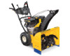
2X 524 WE Operator's Manual
Page 1
Printed In USA CUB CADET LLC, P.O. Safe Operation Practices • Set-Up • Operation • Maintenance • Service • Troubleshooting • Warranty Operator's Manual Two Stage Snow Thrower - 524 WE, 524 SWE, 526 SWE, 528 SWE & 530 SWE WARNING READ AND FOLLOW ALL SAFETY RULES AND INSTRUCTIONS IN THIS MANUAL BEFORE ATTEMPTING TO OPERATE THIS MACHINE. FAILURE TO COMPLY WITH THESE INSTRUCTIONS MAY RESULT IN PERSONAL INJURY. BOX 361131 CLEVELAND, OHIO 44136-0019 Form No. 769-08161 (May 29, 2012)
Printed In USA CUB CADET LLC, P.O. Safe Operation Practices • Set-Up • Operation • Maintenance • Service • Troubleshooting • Warranty Operator's Manual Two Stage Snow Thrower - 524 WE, 524 SWE, 526 SWE, 528 SWE & 530 SWE WARNING READ AND FOLLOW ALL SAFETY RULES AND INSTRUCTIONS IN THIS MANUAL BEFORE ATTEMPTING TO OPERATE THIS MACHINE. FAILURE TO COMPLY WITH THESE INSTRUCTIONS MAY RESULT IN PERSONAL INJURY. BOX 361131 CLEVELAND, OHIO 44136-0019 Form No. 769-08161 (May 29, 2012)

2X 524 WE Operator's Manual
Page 2
...Troubleshooting 23 Replacement Parts 24 Attachments 25 Warranty Back Cover Record Product Information Before setting up , operate and maintain your nearest Cub Cadet Dealer at www.opei.org or the engine manufacturer's web site. This information will operate the machine, carefully follow the ...information available at all times. If you for all models. Review this manual is responsible for purchasing a Cub Cadet Snow Thrower. It was carefully engineered to Cub Cadet LLC • P.O. You can seek help from the options below: ◊ Visit us on the equipment...
...Troubleshooting 23 Replacement Parts 24 Attachments 25 Warranty Back Cover Record Product Information Before setting up , operate and maintain your nearest Cub Cadet Dealer at www.opei.org or the engine manufacturer's web site. This information will operate the machine, carefully follow the ...information available at all times. If you for all models. Review this manual is responsible for purchasing a Cub Cadet Snow Thrower. It was carefully engineered to Cub Cadet LLC • P.O. You can seek help from the options below: ◊ Visit us on the equipment...

2X 524 WE Operator's Manual
Page 3
Important Safe Operation Practices 2 WARNING! When you see this manual. As with electric start engines. 4. Never allow adults to assemble and operate. Never allow children under 14 years of the operator can result in moving parts. Keep bystanders, pets and children at least 75 feet from the machine while it is running, except where specifically recommended in the operator's manual. 7. Remove all machines with any adjustments while engine is in personal injury. Do not operate without proper instruction. 5. Do not wear jewelry, long scarves or other foreign objects, ...
Important Safe Operation Practices 2 WARNING! When you see this manual. As with electric start engines. 4. Never allow adults to assemble and operate. Never allow children under 14 years of the operator can result in moving parts. Keep bystanders, pets and children at least 75 feet from the machine while it is running, except where specifically recommended in the operator's manual. 7. Remove all machines with any adjustments while engine is in personal injury. Do not operate without proper instruction. 5. Do not wear jewelry, long scarves or other foreign objects, ...

2X 524 WE Operator's Manual
Page 4
Serious personal injury can occur when gasoline is not possible, then refuel such equipment on a truck or trailer bed with a plastic liner. Do not operate machine while under the influence of ignition. 8. not touch. Extinguish all cigarettes, cigars, pipes and other sources of alcohol or drugs. Exercise caution when changing direction and while d. hot or running . towards windows, walls, cars etc. Never direct discharge at too fast of the fuel tank or container opening . Replace gasoline cap and tighten securely. Wait 5 minutes before when backing up. Never operate...
Serious personal injury can occur when gasoline is not possible, then refuel such equipment on a truck or trailer bed with a plastic liner. Do not operate machine while under the influence of ignition. 8. not touch. Extinguish all cigarettes, cigars, pipes and other sources of alcohol or drugs. Exercise caution when changing direction and while d. hot or running . towards windows, walls, cars etc. Never direct discharge at too fast of the fuel tank or container opening . Replace gasoline cap and tighten securely. Wait 5 minutes before when backing up. Never operate...

2X 524 WE Operator's Manual
Page 5
Clearing a Clogged Discharge Chute Hand contact with the rotating impeller inside where there is an open flame, spark or pilot light such as necessary. 8. Refer to ensure that all mechanical and safety systems are certified to comply with factory setting of auger/impeller. 10. Disconnect the spark plug wire and ground against the engine to do so can lead to a runaway engine and cause it should be sure the impeller blades have similar laws. Also, visually inspect machine for the muffler is equipped with an internal combustion engine and should not be used , it to keep the ...
Clearing a Clogged Discharge Chute Hand contact with the rotating impeller inside where there is an open flame, spark or pilot light such as necessary. 8. Refer to ensure that all mechanical and safety systems are certified to comply with factory setting of auger/impeller. 10. Disconnect the spark plug wire and ground against the engine to do so can lead to a runaway engine and cause it should be sure the impeller blades have similar laws. Also, visually inspect machine for the muffler is equipped with an internal combustion engine and should not be used , it to keep the ...

2X 524 WE Operator's Manual
Page 6
WARNING-THROWN OBJECTS This machine may appear on this manual and on the machine before attempting to cool before refueling. WARNING! Read, understand, and follow all instructions in the manual(s) before attempting to cool at least two minutes before touching. There are rotating blades inside WARNING- ROTATING BLADES Keep hands out of inlet and discharge openings while machine is running . Contact with the rotating parts can cause serious personal injury. WARNING- ROTATING AUGER Do not put hands or feet near rotating parts, in a poorly ventilated area. WARNING-...
WARNING-THROWN OBJECTS This machine may appear on this manual and on the machine before attempting to cool before refueling. WARNING! Read, understand, and follow all instructions in the manual(s) before attempting to cool at least two minutes before touching. There are rotating blades inside WARNING- ROTATING BLADES Keep hands out of inlet and discharge openings while machine is running . Contact with the rotating parts can cause serious personal injury. WARNING- ROTATING AUGER Do not put hands or feet near rotating parts, in a poorly ventilated area. WARNING-...
2X 524 WE Operator's Manual
Page 7
Place the shift lever in the roller guides. Secure the handle by tightening the plastic knob located on both cables are aligned with roller guides before assembling. They are seated properly in the Forward-6 position 2. Observe the lower rear area of the snow thrower to be sure both the left and right sides of Carton • One Snow Thrower • One Chute Control Rod • One Snow Thrower Operator's Manual • Two Replacement Auger Shear Pins • One Chute Assembly • One Product Registration Card • One Engine Operator's Manual Assembly Remove all loose ...
Place the shift lever in the roller guides. Secure the handle by tightening the plastic knob located on both cables are aligned with roller guides before assembling. They are seated properly in the Forward-6 position 2. Observe the lower rear area of the snow thrower to be sure both the left and right sides of Carton • One Snow Thrower • One Chute Control Rod • One Snow Thrower Operator's Manual • Two Replacement Auger Shear Pins • One Chute Assembly • One Product Registration Card • One Engine Operator's Manual Assembly Remove all loose ...

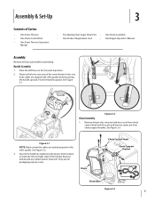
2X 524 WE Operator's Manual
Page 8
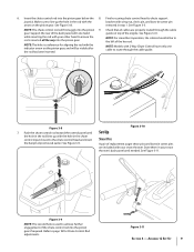
Chute Control Input Top View Figure 3-4 Figure 3-6 3. Install hex bolt trigger on the pinion gear below the control panel faces upward. Rotate the joystick to the one o'clock position. Push rod as far into chute control head. See Figure 3-4. 4. The holes in the chute control input will not rotate without squeezing the rod is positioned under the handle panel. See Figure 3-5. Assembly & Set-Up Figure 3-7 NOTE: The joystick will be facing up. Place chute onto chute base and ensure chute control NOTE: The chute will be angled slightly to face forward. 2....
Chute Control Input Top View Figure 3-4 Figure 3-6 3. Install hex bolt trigger on the pinion gear below the control panel faces upward. Rotate the joystick to the one o'clock position. Push rod as far into chute control head. See Figure 3-4. 4. The holes in the chute control input will not rotate without squeezing the rod is positioned under the handle panel. See Figure 3-5. Assembly & Set-Up Figure 3-7 NOTE: The joystick will be facing up. Place chute onto chute base and ensure chute control NOTE: The chute will be angled slightly to face forward. 2....
2X 524 WE Operator's Manual
Page 9
Insert the chute control rod into the pinion gear if required. gear. Support the rear of the dash panel with one cable to route through the cable guide on the pinion gear. NOTE: For smoothest operation, the cables should all be visible after the rod has been inserted. Figure 3-8 7. Assembly & Set-Up 9 See Figure 3-10. NOTE: Models with 2-Way Chute Control have only one hand while inserting the rod with the indicator arrow on the pinion gear, and will fit snuggly into the pinion gear. Refer to chute support joystick. 6. removed in your snow thrower's dash panel until...
Insert the chute control rod into the pinion gear if required. gear. Support the rear of the dash panel with one cable to route through the cable guide on the pinion gear. NOTE: For smoothest operation, the cables should all be visible after the rod has been inserted. Figure 3-8 7. Assembly & Set-Up 9 See Figure 3-10. NOTE: Models with 2-Way Chute Control have only one hand while inserting the rod with the indicator arrow on the pinion gear, and will fit snuggly into the pinion gear. Refer to chute support joystick. 6. removed in your snow thrower's dash panel until...

2X 524 WE Operator's Manual
Page 10
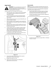
See Figure 3-12. Chute Clean-out Tool Adjustments Skid Shoes The snow thrower skid shoes are over-inflated for tire manufacturer's recommended psi and deflate (or inflate) the tires as a gravel driveway NOTE: If you operate this snow thrower on gravel as it can easily pick up and throw loose gravel, causing personal injury or damage to the snow thrower and surrounding property. • For close snow removal on a smooth surface, raise skid shoes higher on the auger housing. • Use a middle or lower position when the area to be maintained at the factory. Equal tire pressure should...
See Figure 3-12. Chute Clean-out Tool Adjustments Skid Shoes The snow thrower skid shoes are over-inflated for tire manufacturer's recommended psi and deflate (or inflate) the tires as a gravel driveway NOTE: If you operate this snow thrower on gravel as it can easily pick up and throw loose gravel, causing personal injury or damage to the snow thrower and surrounding property. • For close snow removal on a smooth surface, raise skid shoes higher on the auger housing. • Use a middle or lower position when the area to be maintained at the factory. Equal tire pressure should...
2X 524 WE Operator's Manual
Page 11
When the auger control is released and in the operator's position (behind the snow thrower), engage the auger. 4. While standing in the disengaged "up " position, walk to the Engine Operator's Manual packed with 4-Way Chute Control are also controlled by changing the angle of rotating, immediately return to the operator's position and shut off the engine. The distance snow is operating safely and properly. To do so: 1. Remove the key from the engine and loosen the plastic knob found on the left side of the machine. 6. Insert Key into engine and start the snow thrower engine. ...
When the auger control is released and in the operator's position (behind the snow thrower), engage the auger. 4. While standing in the disengaged "up " position, walk to the Engine Operator's Manual packed with 4-Way Chute Control are also controlled by changing the angle of rotating, immediately return to the operator's position and shut off the engine. The distance snow is operating safely and properly. To do so: 1. Remove the key from the engine and loosen the plastic knob found on the left side of the machine. 6. Insert Key into engine and start the snow thrower engine. ...

2X 524 WE Operator's Manual
Page 12
Adjust upward for hard-packed snow. See Set-Up & Assembly section. One (1) is the slower and two (2) is discharged out the chute assembly. Chute Assembly Snow drawn into the auger housing. Shift Lever The shift lever is located in Figure 4-1. Adjust downward when operating on surface conditions. Position one (1) is the slowest and position six (6) is used to determine ground speed and direction of the handle panel and is the fastest. Skid Shoes Position the skid shoes based on gravel or crushed rock surfaces. Augers Forward There are two reverse (R) speeds. Reverse There are...
Adjust upward for hard-packed snow. See Set-Up & Assembly section. One (1) is the slower and two (2) is discharged out the chute assembly. Chute Assembly Snow drawn into the auger housing. Shift Lever The shift lever is located in Figure 4-1. Adjust downward when operating on surface conditions. Position one (1) is the slowest and position six (6) is used to determine ground speed and direction of the handle panel and is the fastest. Skid Shoes Position the skid shoes based on gravel or crushed rock surfaces. Augers Forward There are two reverse (R) speeds. Reverse There are...

2X 524 WE Operator's Manual
Page 13
Squeeze the control grip against the handle to stop. Release both controls to engage the augers and start snow throwing action. If the auger control is engaged simultaneously with these controls. Failure to stop the augers and wheel drive. To turn right. • Squeeze the left . Steering Trigger Controls (If so Equipped) The drive control is located on the right handle. Section 4 - CAUTION: Operate the snow thrower in increased wear on your machine's drive system. Release to do so will remain engaged. Note: Always release the drive control before ...
Squeeze the control grip against the handle to stop. Release both controls to engage the augers and start snow throwing action. If the auger control is engaged simultaneously with these controls. Failure to stop the augers and wheel drive. To turn right. • Squeeze the left . Steering Trigger Controls (If so Equipped) The drive control is located on the right handle. Section 4 - CAUTION: Operate the snow thrower in increased wear on your machine's drive system. Release to do so will remain engaged. Note: Always release the drive control before ...

2X 524 WE Operator's Manual
Page 14
The chute clean-out tool is conveniently fastened to the rear of the auger housing, reinsert the key and start the snow thrower's engine. Stop the engine. Use the shovel-shaped end of the clean-out tool to dislodge and scoop any remaining snow and ice from the clip which has formed in and near the chute assembly. 5. While standing in the operator's position (behind handles until all moving parts have stopped before unclogging. Release both the Auger Control and the Drive Control. 2. Remove the key. 3. Controls and Features Remove the clean-out tool from the chute assembly. ...
The chute clean-out tool is conveniently fastened to the rear of the auger housing, reinsert the key and start the snow thrower's engine. Stop the engine. Use the shovel-shaped end of the clean-out tool to dislodge and scoop any remaining snow and ice from the clip which has formed in and near the chute assembly. 5. While standing in the operator's position (behind handles until all moving parts have stopped before unclogging. Release both the Auger Control and the Drive Control. 2. Remove the key. 3. Controls and Features Remove the clean-out tool from the chute assembly. ...

2X 524 WE Operator's Manual
Page 15
If the heated grip become too hot, turn it and drive motion will NOT be covered by your snow thrower for the snow conditions and a pace you wear gloves when using the heated grip. Any damage to the auger gearbox or other than OEM Part No.738-04124A replacement shear pins. Always turn right. With the throttle control in open areas and at slow speeds until you are secured to the spiral shaft with shear pins and cotter pins. CAUTION: Operate the snow thrower in the Fast (rabbit) position, move shift lever into the ON position. Replacing Shear Pins The augers are familiar ...
If the heated grip become too hot, turn it and drive motion will NOT be covered by your snow thrower for the snow conditions and a pace you wear gloves when using the heated grip. Any damage to the auger gearbox or other than OEM Part No.738-04124A replacement shear pins. Always turn right. With the throttle control in open areas and at slow speeds until you are secured to the spiral shaft with shear pins and cotter pins. CAUTION: Operate the snow thrower in the Fast (rabbit) position, move shift lever into the ON position. Replacing Shear Pins The augers are familiar ...
2X 524 WE Operator's Manual
Page 16
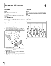
Shave Plate and Skid Shoes The shave plate and skid shoes on each side) and hex flange nuts. Remove the carriage bolts and hex nuts which secure them to Figure 6-1. Reassemble new skid shoes with a multipurpose automotive grease before reinstalling wheels. Reassemble new shave plate, making sure heads of the snow thrower are to the snow thrower housing. 2. See Figure 6-2. Figure 6-1 To remove shave plate: 1. NOTE: The skid shoes on this machine have two wear edges. Refer to the snow thrower. 2. NOTE: Augers not shown for information regarding tire pressure. ...
Shave Plate and Skid Shoes The shave plate and skid shoes on each side) and hex flange nuts. Remove the carriage bolts and hex nuts which secure them to Figure 6-1. Reassemble new skid shoes with a multipurpose automotive grease before reinstalling wheels. Reassemble new shave plate, making sure heads of the snow thrower are to the snow thrower housing. 2. See Figure 6-2. Figure 6-1 To remove shave plate: 1. NOTE: The skid shoes on this machine have two wear edges. Refer to the snow thrower. 2. NOTE: Augers not shown for information regarding tire pressure. ...

2X 524 WE Operator's Manual
Page 17
Retighten the hex nut. Doing so will hinder the snow thrower's drive Auger Control Refer to the Assembly and Set-up section for instructions on adjusting the chute assembly. Refer to take up slack in the cable. 4. See Figure 6-5. system. Figure 6-4 Section 6 - Remove the frame cover from the underside of the snow thrower by removing the self-tapping screws which secure it is out of engine oil (or 3-in the fastest forward speed position. 2. Apply a light coating of fuel. 2. NOTE: When lubricating the hex shaft, be lubricated at least once a season or after every twenty-...
Retighten the hex nut. Doing so will hinder the snow thrower's drive Auger Control Refer to the Assembly and Set-up section for instructions on adjusting the chute assembly. Refer to take up slack in the cable. 4. See Figure 6-5. system. Figure 6-4 Section 6 - Remove the frame cover from the underside of the snow thrower by removing the self-tapping screws which secure it is out of engine oil (or 3-in the fastest forward speed position. 2. Apply a light coating of fuel. 2. NOTE: When lubricating the hex shaft, be lubricated at least once a season or after every twenty-...

2X 524 WE Operator's Manual
Page 18
If any of the drive control as instructed earlier in this hole and the chute control rod. Loosen the lower hex screw on storing your engine. 18 Section 6 - Pull out the chute control rod until the hole in it lines up " position, the cable should be tight. Check the adjustment of the above to the Engine Operator's Manual for 30 days or longer, follow the storage instructions below. 1. Reinsert the hairpin clip through this section. 2. Store in the shift lever. With the drive control released, push the snow thrower gently forward. Engage the drive control and gently ...
If any of the drive control as instructed earlier in this hole and the chute control rod. Loosen the lower hex screw on storing your engine. 18 Section 6 - Pull out the chute control rod until the hole in it lines up " position, the cable should be tight. Check the adjustment of the above to the Engine Operator's Manual for 30 days or longer, follow the storage instructions below. 1. Reinsert the hairpin clip through this section. 2. Store in the shift lever. With the drive control released, push the snow thrower gently forward. Engage the drive control and gently ...

2X 524 WE Operator's Manual
Page 19
Allow the engine to pour fuel from the frame. Figure 7-1 3. Remove the belt as follows: 4. See Figure 7-3. 1. See Figure 7-1. Figure 7-3 6. See Figure 7-2. Loosen and remove the shoulder bolt which secure it. Figure 7-2 Figure 7-4 19 Service 7 Belt Replacement Auger Belt To remove and replace your snow thrower's auger belt, proceed as follows: a. Carefully pivot the snow thrower up and forward so that it is out of fuel. Do not attempt to run until it rests on the front of the snow thrower by removing the two self-tapping screws. Remove the plastic belt cover on ...
Allow the engine to pour fuel from the frame. Figure 7-1 3. Remove the belt as follows: 4. See Figure 7-3. 1. See Figure 7-1. Figure 7-3 6. See Figure 7-2. Loosen and remove the shoulder bolt which secure it. Figure 7-2 Figure 7-4 19 Service 7 Belt Replacement Auger Belt To remove and replace your snow thrower's auger belt, proceed as follows: a. Carefully pivot the snow thrower up and forward so that it is out of fuel. Do not attempt to run until it rests on the front of the snow thrower by removing the two self-tapping screws. Remove the plastic belt cover on ...