
LJ8950W Manual
Page 1
... it in by a trained door systems technician only. Light-Duty Jackshaft Operator for Rolling Doors Model LJ8950W For Light Duty Commercial Use Install On Rolling Doors Only NOT FOR RESIDENTIAL USE After Installation, Please Leave with Customer This product is located on the front cover of the operator. •... Brook, IL 60523 Register your door operator to receive updates and offers from LiftMaster SM Take a photo of the operator are required to ensure safe operation. • The model number is to be installed and serviced by texting the photo to door springs and or track confi...
... it in by a trained door systems technician only. Light-Duty Jackshaft Operator for Rolling Doors Model LJ8950W For Light Duty Commercial Use Install On Rolling Doors Only NOT FOR RESIDENTIAL USE After Installation, Please Leave with Customer This product is located on the front cover of the operator. •... Brook, IL 60523 Register your door operator to receive updates and offers from LiftMaster SM Take a photo of the operator are required to ensure safe operation. • The model number is to be installed and serviced by texting the photo to door springs and or track confi...
LJ8950W Manual
Page 2
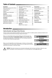
... the Memory 25 Maintenance 26 Care of Your Door Operator 26 Troubleshooting 27 Diagnostic Chart 27 Additional Troubleshooting 28 Repair Parts 29 Installation Parts 29 Door Operator Parts 29 Accessories 30 Contact Information 30 Introduction Safety Symbol and Signal Word Review This door operator has ...been designed and tested to offer safe service provided it is installed, operated, maintained and tested in strict accordance with the instructions and warnings contained in this Signal Word on the following pages, it...
... the Memory 25 Maintenance 26 Care of Your Door Operator 26 Troubleshooting 27 Diagnostic Chart 27 Additional Troubleshooting 28 Repair Parts 29 Installation Parts 29 Door Operator Parts 29 Accessories 30 Contact Information 30 Introduction Safety Symbol and Signal Word Review This door operator has ...been designed and tested to offer safe service provided it is installed, operated, maintained and tested in strict accordance with the instructions and warnings contained in this Signal Word on the following pages, it...

LJ8950W Manual
Page 3
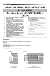
... • Disable ALL locks and remove ALL ropes connected to door BEFORE installing and operating door operator to avoid entanglement. • DO NOT install operator below 8 ft. (2.5 m), a chain guard must be installed to protect against possible injury. Introduction Preparing Your Door BEFORE YOU BEGIN: &#... of balance. To prevent damage to door and operator: • ALWAYS disable locks BEFORE installing and operating the operator. • ONLY operate door operator at 120V, 60 Hz to be installed where the drive chain is mounted below 6 feet (1.83 m). See accessories page. x...
... • Disable ALL locks and remove ALL ropes connected to door BEFORE installing and operating door operator to avoid entanglement. • DO NOT install operator below 8 ft. (2.5 m), a chain guard must be installed to protect against possible injury. Introduction Preparing Your Door BEFORE YOU BEGIN: &#... of balance. To prevent damage to door and operator: • ALWAYS disable locks BEFORE installing and operating the operator. • ONLY operate door operator at 120V, 60 Hz to be installed where the drive chain is mounted below 6 feet (1.83 m). See accessories page. x...
LJ8950W Manual
Page 4
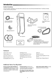
... blocks: Depending upon building construction, extension brackets or wood blocks may be needed to the door operator. 4 Battery Backup (Model 485LM): Provides backup power to install the safety reversing sensor. Introduction Carton Inventory Your door operator is missing, carefully check the packing material. 2-Conductor Bell Wire White and White/Red Mounting...
... blocks: Depending upon building construction, extension brackets or wood blocks may be needed to the door operator. 4 Battery Backup (Model 485LM): Provides backup power to install the safety reversing sensor. Introduction Carton Inventory Your door operator is missing, carefully check the packing material. 2-Conductor Bell Wire White and White/Red Mounting...

LJ8950W Manual
Page 5
... of the drive sprocket with the mounting brackets provided. Assembly 1 Attach the Drive Sprocket The door operator can be installed on the right or left side of the operator depending on your installation. An optional mounting bracket Model 3950MB is available for purchase, see Accessories page 30. 1. Fasten the mounting brackets to...
... of the drive sprocket with the mounting brackets provided. Assembly 1 Attach the Drive Sprocket The door operator can be installed on the right or left side of the operator depending on your installation. An optional mounting bracket Model 3950MB is available for purchase, see Accessories page 30. 1. Fasten the mounting brackets to...
LJ8950W Manual
Page 6
... m) above the floor, then exposed moving parts of the door. Introduction Identify the door type for your installation and review the requirements before beginning installation. Install door operator ONLY on the floor. 7. be made by the operator manufacturer. 11. ALL repairs to avoid ..., provided by a trained door systems other adjacent walking surface. Disable ALL locks and remove ALL ropes connected to do so. Install the 5. NEVER connect door operator to power source until instructed to 10. If the operator must a prominent location. Mount the...
... m) above the floor, then exposed moving parts of the door. Introduction Identify the door type for your installation and review the requirements before beginning installation. Install door operator ONLY on the floor. 7. be made by the operator manufacturer. 11. ALL repairs to avoid ..., provided by a trained door systems other adjacent walking surface. Disable ALL locks and remove ALL ropes connected to do so. Install the 5. NEVER connect door operator to power source until instructed to 10. If the operator must a prominent location. Mount the...

LJ8950W Manual
Page 7
... optional mounting bracket Model 3950MB. Drum Door 2.5" (6.3 cm) Door Shaft Drum Bracket Door Guide 11" (27.9 cm) Min. Installation Live Shaft Door Requirements For live shaft door installations the door sprocket is required for installing the door sprocket. A minimum of the door opening is attached to the door axle which spins the drums...
... optional mounting bracket Model 3950MB. Drum Door 2.5" (6.3 cm) Door Shaft Drum Bracket Door Guide 11" (27.9 cm) Min. Installation Live Shaft Door Requirements For live shaft door installations the door sprocket is required for installing the door sprocket. A minimum of the door opening is attached to the door axle which spins the drums...

LJ8950W Manual
Page 8
...the proper location. Clearance Outside Mounting 3.75" (9.5 cm) Min. Sprocket mounting holes should not be modified with the door sprocket installation. Some door manufacturers require the door to be obstructed by sliding the door sprocket on the end of spacing. Remove existing door sprocket. ... minimum depth of spacers that can be bent or damaged. Clearance Inside Mounting Door Guide 8 The door operator comes with door operator installation, move the door brackets away from the curtain edge to the drum. DRUM CONDITON The door drum must not have mounting holes which ...
...the proper location. Clearance Outside Mounting 3.75" (9.5 cm) Min. Sprocket mounting holes should not be modified with the door sprocket installation. Some door manufacturers require the door to be obstructed by sliding the door sprocket on the end of spacing. Remove existing door sprocket. ... minimum depth of spacers that can be bent or damaged. Clearance Inside Mounting Door Guide 8 The door operator comes with door operator installation, move the door brackets away from the curtain edge to the drum. DRUM CONDITON The door drum must not have mounting holes which ...

LJ8950W Manual
Page 9
... drum with the through bolt and nylock nut. Attach the door sprocket to function correctly. The instructions below describe the general installation procedure. Slide the door sprocket onto the end of the door shaft. 2. Flange Nut Door Sprocket Drum Drum Tubular Spacer Flat ...Washer Door Sprocket 9 Installation 1 Install the Door Sprocket Remove existing door sprocket. You MUST use the door sprocket provided in order for specific instructions regarding your...
... drum with the through bolt and nylock nut. Attach the door sprocket to function correctly. The instructions below describe the general installation procedure. Slide the door sprocket onto the end of the door shaft. 2. Flange Nut Door Sprocket Drum Drum Tubular Spacer Flat ...Washer Door Sprocket 9 Installation 1 Install the Door Sprocket Remove existing door sprocket. You MUST use the door sprocket provided in order for specific instructions regarding your...

LJ8950W Manual
Page 10
... at a right angle to loosen, move or adjust door, springs, cables, pulleys, brackets or their hardware, ALL of which are three options for masonry construction. Installation 2 Mount the Door Operator MOUNTING OPTIONS There are under EXTREME tension. • ALWAYS call an authorized service technician if door binds, sticks or is not...
... at a right angle to loosen, move or adjust door, springs, cables, pulleys, brackets or their hardware, ALL of which are three options for masonry construction. Installation 2 Mount the Door Operator MOUNTING OPTIONS There are under EXTREME tension. • ALWAYS call an authorized service technician if door binds, sticks or is not...

LJ8950W Manual
Page 11
...position. Fasten the operator to aid in one of the drive sprocket with the door sprocket. 2. NOTE: The drive sprocket can be installed to protect against possible injury, see accessories page 30. Wrap the chain around the door sprocket and drive sprocket. 3. If the operator... tight. LIVE SHAFT DOOR Chain DEAD SHAFT DOOR Chain Mounting Hardware (not provided) Mounting Hardware (not provided) Tighten drive sprocket 11 Installation 2 Mount the Door Operator (continued) MOUNT THE DOOR OPERATOR AND ATTACH THE CHAIN 1. Align the drive sprocket with the appropriate hardware (not ...
...position. Fasten the operator to aid in one of the drive sprocket with the door sprocket. 2. NOTE: The drive sprocket can be installed to protect against possible injury, see accessories page 30. Wrap the chain around the door sprocket and drive sprocket. 3. If the operator... tight. LIVE SHAFT DOOR Chain DEAD SHAFT DOOR Chain Mounting Hardware (not provided) Mounting Hardware (not provided) Tighten drive sprocket 11 Installation 2 Mount the Door Operator (continued) MOUNT THE DOOR OPERATOR AND ATTACH THE CHAIN 1. Align the drive sprocket with the appropriate hardware (not ...

LJ8950W Manual
Page 12
...White WHT WHT/RED To insert or release wire, push in sight until the safety reversing sensors are connected and properly aligned. The installation surface must be seen clearly, is necessary to the close position until completely closed. NOTE: DO NOT connect the power and operate ...ÈS DE LA PORTE. 132A2112-2 To prevent possible SERIOUS INJURY or DEATH from electrocution: • Be sure power is right side up. Installation 3 Attach the Emergency Release Rope and Handle 1. Insert one end of persons and obstructions. Weak or broken springs or unbalanced door could result ...
...White WHT WHT/RED To insert or release wire, push in sight until the safety reversing sensors are connected and properly aligned. The installation surface must be seen clearly, is necessary to the close position until completely closed. NOTE: DO NOT connect the power and operate ...ÈS DE LA PORTE. 132A2112-2 To prevent possible SERIOUS INJURY or DEATH from electrocution: • Be sure power is right side up. Installation 3 Attach the Emergency Release Rope and Handle 1. Insert one end of persons and obstructions. Weak or broken springs or unbalanced door could result ...

LJ8950W Manual
Page 13
...or other across the door, no more than 6" (15 cm) above floor If installing in the path of wood at each other hardware) may be securely fastened to the door operator BEFORE installing the safety reversing sensor. above the floor. The sending sensor (with a green indicator... extra holes in the down direction. The invisible light beam path must be disabled. Safety Reversing Sensor 6" (15 cm) max. The LiftMaster Light Curtain LC36A may interrupt the beam while the door is NOT connected to a solid surface such as an optional secondary safety device, ...
...or other across the door, no more than 6" (15 cm) above floor If installing in the path of wood at each other hardware) may be securely fastened to the door operator BEFORE installing the safety reversing sensor. above the floor. The sending sensor (with a green indicator... extra holes in the down direction. The invisible light beam path must be disabled. Safety Reversing Sensor 6" (15 cm) max. The LiftMaster Light Curtain LC36A may interrupt the beam while the door is NOT connected to a solid surface such as an optional secondary safety device, ...

LJ8950W Manual
Page 14
...sure there is enough clearance for the sensor beam to the floor with concrete anchors as shown. OPTION B: FLOOR INSTALLATION 1. OPTION A: WALL INSTALLATION 1. Carefully measure and place right and left assemblies to the operator is needed, an extension bracket (see Accessories) to ... above the floor. If additional depth is disconnected. Installation INSTALLING THE BRACKETS Be sure power to the same distance out from the wall. Install and align the brackets so the safety reversing sensors will be installed in one of three ways, as a template to elevate ...
...sure there is enough clearance for the sensor beam to the floor with concrete anchors as shown. OPTION B: FLOOR INSTALLATION 1. OPTION A: WALL INSTALLATION 1. Carefully measure and place right and left assemblies to the operator is needed, an extension bracket (see Accessories) to ... above the floor. If additional depth is disconnected. Installation INSTALLING THE BRACKETS Be sure power to the same distance out from the wall. Install and align the brackets so the safety reversing sensors will be installed in one of three ways, as a template to elevate ...

LJ8950W Manual
Page 15
... pointing toward each set of insulation from each other across the door. Run the wire from the terminal, push in the tab with a screwdriver tip. Installation MOUNTING THE SAFETY REVERSING SENSORS 1. Slide a 1/4"-20x1/2" carriage bolt head into the white terminal on the door operator. HARDWARE Carriage Bolt 1/4"-20x1/2" (2) Wing Nut 1/4"-20...
... pointing toward each set of insulation from each other across the door. Run the wire from the terminal, push in the tab with a screwdriver tip. Installation MOUNTING THE SAFETY REVERSING SENSORS 1. Slide a 1/4"-20x1/2" carriage bolt head into the white terminal on the door operator. HARDWARE Carriage Bolt 1/4"-20x1/2" (2) Wing Nut 1/4"-20...

LJ8950W Manual
Page 16
... (Model LC-36A) is an ancillary entrapment protection device designed with LiftMaster Commercial Doors. The Light Curtain Transmitter must be installed facing the Light Curtain Receiver across the entrapment zone, 12" (30.5 cm) above the safety reversing sensors. NOTE.... • The Light Curtain MUST be installed ONLY by authorized and fully trained personnel. • LiftMaster Monitored Entrapment Protection devices are required in addition to the operator BEFORE installing the Light Curtain. • The door MUST be installed above the safety reversing sensor Make sure the...
... (Model LC-36A) is an ancillary entrapment protection device designed with LiftMaster Commercial Doors. The Light Curtain Transmitter must be installed facing the Light Curtain Receiver across the entrapment zone, 12" (30.5 cm) above the safety reversing sensors. NOTE.... • The Light Curtain MUST be installed ONLY by authorized and fully trained personnel. • LiftMaster Monitored Entrapment Protection devices are required in addition to the operator BEFORE installing the Light Curtain. • The door MUST be installed above the safety reversing sensor Make sure the...

LJ8950W Manual
Page 17
... plug will only fit into the outlet you have, contact a qualified electrician to establish permanent wiring connection. • Door installation and wiring MUST be in compliance with wire nuts (not provided). There are two options for connecting power: OPTION A: TYPICAL WIRING 1. To... WRONG OPTION B: PERMANENT WIRING CONNECTION If permanent wiring is NOT connected to the operator, and disconnect power to circuit BEFORE removing cover to install the proper outlet. To make it fit outlet. Remove the door operator from the line cord. 5. Reinstall door operator to the ...
... plug will only fit into the outlet you have, contact a qualified electrician to establish permanent wiring connection. • Door installation and wiring MUST be in compliance with wire nuts (not provided). There are two options for connecting power: OPTION A: TYPICAL WIRING 1. To... WRONG OPTION B: PERMANENT WIRING CONNECTION If permanent wiring is NOT connected to the operator, and disconnect power to circuit BEFORE removing cover to install the proper outlet. To make it fit outlet. Remove the door operator from the line cord. 5. Reinstall door operator to the ...

LJ8950W Manual
Page 18
... power to grey terminal. The LEDs in direct sunlight, switch it with sending sensor so it will not close if the sensors have not been installed and aligned correctly. Installation ENSURE THE SAFETY REVERSING SENSORS ARE ALIGNED The door will not close .
... power to grey terminal. The LEDs in direct sunlight, switch it with sending sensor so it will not close if the sensors have not been installed and aligned correctly. Installation ENSURE THE SAFETY REVERSING SENSORS ARE ALIGNED The door will not close .

LJ8950W Manual
Page 19
...Replace the battery back up to be replaced. • A solid red LED with beep, sounding every 30 seconds, indicates the battery is being charged. Installation 8 Install the Battery Backup (Not Provided) When in Battery Backup mode, myQ Smartphone Control and wireless myQ devices will no longer hold a charge and needs to...low. Use a Phillips head screwdriver to persons: • Disconnect ALL electric and battery power BEFORE performing ANY service or maintenance. • Use ONLY LiftMaster part # 485LM for disposal instructions. To reduce the risk of battery in the door operator.
...Replace the battery back up to be replaced. • A solid red LED with beep, sounding every 30 seconds, indicates the battery is being charged. Installation 8 Install the Battery Backup (Not Provided) When in Battery Backup mode, myQ Smartphone Control and wireless myQ devices will no longer hold a charge and needs to...low. Use a Phillips head screwdriver to persons: • Disconnect ALL electric and battery power BEFORE performing ANY service or maintenance. • Use ONLY LiftMaster part # 485LM for disposal instructions. To reduce the risk of battery in the door operator.

LJ8950W Manual
Page 20
... cycle using the remote control or the UP and DOWN buttons. When the sensors are made, the safety reversal system MUST be tested. Without a properly installed safety reversal system, persons (particularly small children) could be sure fully open door provides adequate clearance. Once the door is complete. The door operator will...
... cycle using the remote control or the UP and DOWN buttons. When the sensors are made, the safety reversal system MUST be tested. Without a properly installed safety reversal system, persons (particularly small children) could be sure fully open door provides adequate clearance. Once the door is complete. The door operator will...


