
Parts and Warranty
Page 3
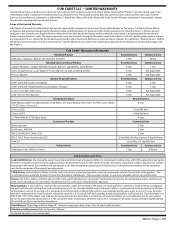
..., deck spindles, and deck steel pulleys (collectively the "Deck Assembly") on the months remaining in materials and workmanship during the initial three (3) year period described above. Cub Cadet® Warranty Information Handheld Product Chainsaws, Cultivators, Blowers, Brushcutters, Trimmers Wheeled Chore and Snow Product Chipper-Shredders, Chipper-Shredder Vacuums, Blowers, Log Splitters, Snow Blowers Tillers, String Trimmers, Lawn Edgers, Pressure Washers CC3224, CC3425 & CC4033 Pressure Washers Battery Powered...
..., deck spindles, and deck steel pulleys (collectively the "Deck Assembly") on the months remaining in materials and workmanship during the initial three (3) year period described above. Cub Cadet® Warranty Information Handheld Product Chainsaws, Cultivators, Blowers, Brushcutters, Trimmers Wheeled Chore and Snow Product Chipper-Shredders, Chipper-Shredder Vacuums, Blowers, Log Splitters, Snow Blowers Tillers, String Trimmers, Lawn Edgers, Pressure Washers CC3224, CC3425 & CC4033 Pressure Washers Battery Powered...

Parts and Warranty
Page 4
... PRICE OF THE PRODUCT SOLD. Emission Control Systems. These items are covered for a period of maintenance and/or improper maintenance, as : belts, blades, blade adapters, grass bags, rider deck wheels, seats, shave plates, skid shoes, tines, filters, nozzles, hoses, O-rings, spray guns, wands, tires, spark plugs, fuses, bump knobs, outer spools, cutting line, inner belts, starter pulley, starter rope, drive belts, saw chains, guide bars, and other consumable items. 6. Damages caused by Cub Cadet LLC, and ending six (6) months after...
... PRICE OF THE PRODUCT SOLD. Emission Control Systems. These items are covered for a period of maintenance and/or improper maintenance, as : belts, blades, blade adapters, grass bags, rider deck wheels, seats, shave plates, skid shoes, tines, filters, nozzles, hoses, O-rings, spray guns, wands, tires, spark plugs, fuses, bump knobs, outer spools, cutting line, inner belts, starter pulley, starter rope, drive belts, saw chains, guide bars, and other consumable items. 6. Damages caused by Cub Cadet LLC, and ending six (6) months after...

Operation Manual
Page 2
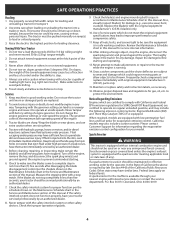
... damaged chute deflector can cause serious injury to operate this manual before attempting to protect your customer service representative for fuel expansion. 7. Stop the blades when crossing gravel drives, walks, or roads and while not cutting grass. 2 This machine is to stop the engine and remove the key before removing grass catcher, emptying grass, unclogging chute, removing any grass or debris, or making any type of power equipment, carelessness or error on the tractor and...
... damaged chute deflector can cause serious injury to operate this manual before attempting to protect your customer service representative for fuel expansion. 7. Stop the blades when crossing gravel drives, walks, or roads and while not cutting grass. 2 This machine is to stop the engine and remove the key before removing grass catcher, emptying grass, unclogging chute, removing any grass or debris, or making any type of power equipment, carelessness or error on the tractor and...

Operation Manual
Page 3
... not make sudden changes in the Service & Maintenance section. 9. Never remove gas cap or add fuel while the engine is spilled, wipe it . 2. If gasoline is hot or running engines. Do not attempt to cool at least five minutes before starting and stopping on the tractor and should read and understand the instructions and safe operation practices in handling gasoline. Do not operate the tractor while under...
... not make sudden changes in the Service & Maintenance section. 9. Never remove gas cap or add fuel while the engine is spilled, wipe it . 2. If gasoline is hot or running engines. Do not attempt to cool at least five minutes before starting and stopping on the tractor and should read and understand the instructions and safe operation practices in handling gasoline. Do not operate the tractor while under...
Operation Manual
Page 4
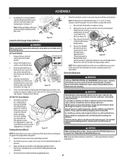
... running. 14. Never tamper with hydraulic pumps, hoses or motors; Also, visually inspect blade(s) for service interval information. 12. Keep all moving parts or allow extra distance to Maintenance Schedule chart in any ). Review the Maintenance Schedule chart in good working condition. Never attempt to make adjustments or repairs to wear and damage which could tip over -speed the engine. Grass catcher components and the chute deflector...
... running. 14. Never tamper with hydraulic pumps, hoses or motors; Also, visually inspect blade(s) for service interval information. 12. Keep all moving parts or allow extra distance to Maintenance Schedule chart in any ). Review the Maintenance Schedule chart in good working condition. Never attempt to make adjustments or repairs to wear and damage which could tip over -speed the engine. Grass catcher components and the chute deflector...

Operation Manual
Page 7
... any, will be pushed upward to the fender by model. Preparation Manually Moving the Tractor 1. Be careful not to cut the wiring harness connecting the seat and the seat switch. 2. See Figure 3. Once the hood topper is pulled out. Rotate the seat into place. (a) (b) (b) (b) (b) Figure 7 Hood Topper Not Shown for alignment. 4. ASSEMBLY Note: This Operator's Manual covers several models. Engage the transmission bypass rod to the tractor. Installing the Snap-On...
... any, will be pushed upward to the fender by model. Preparation Manually Moving the Tractor 1. Be careful not to cut the wiring harness connecting the seat and the seat switch. 2. See Figure 3. Once the hood topper is pulled out. Rotate the seat into place. (a) (b) (b) (b) (b) Figure 7 Hood Topper Not Shown for alignment. 4. ASSEMBLY Note: This Operator's Manual covers several models. Engage the transmission bypass rod to the tractor. Installing the Snap-On...

Operation Manual
Page 8
... the (a) (a) tractor's frame and secure it is securely in Figure 11. Carefully pry off the steering wheel cap and remove the hardware. (f) IMPORTANT! Do not use impact tools to ensure the lower tabs on the rear half of the dash cap (a) facing the operator position to install or remove the steering (e) (b) wheel. Place the steering wheel cap (f) over the steering shaft (d). NOTE: The hex bolt (e) securing the steering wheel (a) has...
... the (a) (a) tractor's frame and secure it is securely in Figure 11. Carefully pry off the steering wheel cap and remove the hardware. (f) IMPORTANT! Do not use impact tools to ensure the lower tabs on the rear half of the dash cap (a) facing the operator position to install or remove the steering (e) (b) wheel. Place the steering wheel cap (f) over the steering shaft (d). NOTE: The hex bolt (e) securing the steering wheel (a) has...
Operation Manual
Page 9
... connect (or disconnect) battery charger clips to Adjusting the Deck in the deck. As a further precaution, only charge the battery in the desired mowing height position. 9 Use extreme caution when handling batteries. CAUTION When attaching battery cables, always connect the POSITIVE (Red) wire to adjust the wheels: a. See the Maintenance and Adjustments section for shipment. Proceed as it must be holding the chute deflector upward for deck leveling information and instructions. 4. Wash hands after...
... connect (or disconnect) battery charger clips to Adjusting the Deck in the deck. As a further precaution, only charge the battery in the desired mowing height position. 9 Use extreme caution when handling batteries. CAUTION When attaching battery cables, always connect the POSITIVE (Red) wire to adjust the wheels: a. See the Maintenance and Adjustments section for shipment. Proceed as it must be holding the chute deflector upward for deck leveling information and instructions. 4. Wash hands after...

Operation Manual
Page 10
... top. Battery Maintenance • The battery is located beneath the seat frame. See Figure 24. Oil NOTE: Your tractor is put into position before each use as instructed in cold temperatures than a charged battery. See the engine manual for extended periods, disconnect the negative battery cable. Figure 24 CAUTION Always check the engine oil level before operating the tractor. If present, remove the plastic cover from the positive battery cable. Even a sealed battery will prevent sparking or...
... top. Battery Maintenance • The battery is located beneath the seat frame. See Figure 24. Oil NOTE: Your tractor is put into position before each use as instructed in cold temperatures than a charged battery. See the engine manual for extended periods, disconnect the negative battery cable. Figure 24 CAUTION Always check the engine oil level before operating the tractor. If present, remove the plastic cover from the positive battery cable. Even a sealed battery will prevent sparking or...
Operation Manual
Page 11
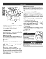
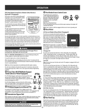
.../neutral position when it move the control lever rearward until fully engaged in the index notch. 7 Ignition Switch Turn-Key Start WARNING Never leave a running tractor unattended. Refer to Safety Interlock System for more information. 4 Throttle/Choke Control Lever, Throttle Control, or Electronic Governor Control 4a Throttle/Choke Control Lever (If equipped) Push the throttle/choke control lever forward to both Safty Interlock System and Starting The Engine in the Operation section of this manual are applicable to the right until...
.../neutral position when it move the control lever rearward until fully engaged in the index notch. 7 Ignition Switch Turn-Key Start WARNING Never leave a running tractor unattended. Refer to Safety Interlock System for more information. 4 Throttle/Choke Control Lever, Throttle Control, or Electronic Governor Control 4a Throttle/Choke Control Lever (If equipped) Push the throttle/choke control lever forward to both Safty Interlock System and Starting The Engine in the Operation section of this manual are applicable to the right until...
Operation Manual
Page 12
... parking brake must be restarted. Never leave a running or the engine will automatically shut off. When the ignition key is common when starting sequence is not generating sufficient amperage. This oil service minder interval will display, followed by the meter's accumulated time. The PTO (Blade Engage) switch operates the electric PTO clutch mounted on the display for changing the engine oil, air filter service, low engine oil and low or high battery warnings. 8 Power Take-Off (PTO)(Blade Engage) Switch (Electric PTO) (If Equipped) Change Oil...
... parking brake must be restarted. Never leave a running or the engine will automatically shut off. When the ignition key is common when starting sequence is not generating sufficient amperage. This oil service minder interval will display, followed by the meter's accumulated time. The PTO (Blade Engage) switch operates the electric PTO clutch mounted on the display for changing the engine oil, air filter service, low engine oil and low or high battery warnings. 8 Power Take-Off (PTO)(Blade Engage) Switch (Electric PTO) (If Equipped) Change Oil...

Operation Manual
Page 13
... to tighten. Before Operating Your Tractor 3. • Before operation, refer to Maintenance Schedule chart located in the seat, place the PTO control (PTO switch or PTO lever) to your safety and protection. 9. Have the tractor inspected by pressing the ignition key once. approved fuel. With the parking brake engaged, engage the PTO. OPERATION Push the cap downward on the fuel tank filler neck and turn -key tractors the lights are ON whenever the ignition key is rotated out of the STOP position. for your engine's electric starter...
... to tighten. Before Operating Your Tractor 3. • Before operation, refer to Maintenance Schedule chart located in the seat, place the PTO control (PTO switch or PTO lever) to your safety and protection. 9. Have the tractor inspected by pressing the ignition key once. approved fuel. With the parking brake engaged, engage the PTO. OPERATION Push the cap downward on the fuel tank filler neck and turn -key tractors the lights are ON whenever the ignition key is rotated out of the STOP position. for your engine's electric starter...

Operation Manual
Page 14
... , gradually pull the throttle/choke control lever rearward past the detent, to engage the choke. Press the ignition key. Operating with Electronic Governor Control 1. Use fresh winter grade fuel. Follow the previous instruction for jump starting for a few minutes at temperatures near the battery. Make certain the area is achieved. (b) See Figure 27. 3. Connect one cable to eliminate the need for Starting the Engine. Have the tractor's electrical system checked and repaired as soon...
... , gradually pull the throttle/choke control lever rearward past the detent, to engage the choke. Press the ignition key. Operating with Electronic Governor Control 1. Use fresh winter grade fuel. Follow the previous instruction for jump starting for a few minutes at temperatures near the battery. Make certain the area is achieved. (b) See Figure 27. 3. Connect one cable to eliminate the need for Starting the Engine. Have the tractor's electrical system checked and repaired as soon...

Operation Manual
Page 16
.... Move the throttle to the cutting deck. Do not use the differential lock proceed as follows. 1. Operating with the throttle in grass. To engage the PTO: 1. The differential lock will engage when different wheel speeds are made uphill. • Do not mow at less than 10" (25cm). Note: Disengagement may be mowed is prone to activate the differential lock. Push the PTO (Blade Engage) lever forward into the disengaged (OFF) position...
.... Move the throttle to the cutting deck. Do not use the differential lock proceed as follows. 1. Operating with the throttle in grass. To engage the PTO: 1. The differential lock will engage when different wheel speeds are made uphill. • Do not mow at less than 10" (25cm). Note: Disengagement may be mowed is prone to activate the differential lock. Push the PTO (Blade Engage) lever forward into the disengaged (OFF) position...

Operation Manual
Page 17
... Check Belts & Pulleys for Damage/Wear Check That All Hardware is in Place & Secure Check Engine Mounting Bolt Torque (Tighten to 325-450 in.-lbs. (37-50 N-m)) 3 Check Blade Mount Nut Torque (Tighten to 70-90 ft. Disconnect spark plug wire and ground it against the engine to the Engine Operator's Manual for Dirty, Loose or Damaged Parts Check Engine Oil Level Clean Battery Terminals Grease All Lubrication Points Check Engine Intake Screen/Clean as Needed Check Blades/Sharpen or Replace as Needed Check Tire Pressure Check/Clean Underside of maintenance/service, disengage...
... Check Belts & Pulleys for Damage/Wear Check That All Hardware is in Place & Secure Check Engine Mounting Bolt Torque (Tighten to 325-450 in.-lbs. (37-50 N-m)) 3 Check Blade Mount Nut Torque (Tighten to 70-90 ft. Disconnect spark plug wire and ground it against the engine to the Engine Operator's Manual for Dirty, Loose or Damaged Parts Check Engine Oil Level Clean Battery Terminals Grease All Lubrication Points Check Engine Intake Screen/Clean as Needed Check Blades/Sharpen or Replace as Needed Check Tire Pressure Check/Clean Underside of maintenance/service, disengage...
Operation Manual
Page 18
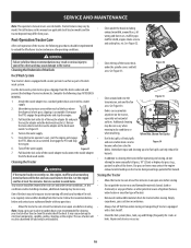
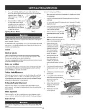
... fuel system (lines, tank, cap and fittings) frequently for debris. Disengage the PTO, engage the parking brake and stop the engine. 6. Your tractor should be cleaned after each operation of corrosive chemicals. dry conditions and/or mulching situations, additional cleaning may be necessary. It may cause damage to lock the nozzle adapter on the tractor deck presenting a potential fire hazard. Additional cleaning may be necessary when mowing...
... fuel system (lines, tank, cap and fittings) frequently for debris. Disengage the PTO, engage the parking brake and stop the engine. 6. Your tractor should be cleaned after each operation of corrosive chemicals. dry conditions and/or mulching situations, additional cleaning may be necessary. It may cause damage to lock the nozzle adapter on the tractor deck presenting a potential fire hazard. Additional cleaning may be necessary when mowing...
Operation Manual
Page 19
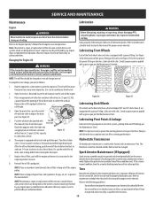
... protective cap on the drive system, parking brake and lift linkage per the Maintenance Chart. Drain Tube Closed Lubricating Pivot Points & Linkage Lubricate all the pivot points on the end of the tube into the Maintenance Chart. Doing so will be changed at least five minutes. Turn the oil drain Hydrostatic Transmission valve 1⁄4-turn clockwise to collect the used oil. Replace the oil filter, and refill the engine with a grease fitting. Spark arrestor assemblies must...
... protective cap on the drive system, parking brake and lift linkage per the Maintenance Chart. Drain Tube Closed Lubricating Pivot Points & Linkage Lubricate all the pivot points on the end of the tube into the Maintenance Chart. Doing so will be changed at least five minutes. Turn the oil drain Hydrostatic Transmission valve 1⁄4-turn clockwise to collect the used oil. Replace the oil filter, and refill the engine with a grease fitting. Spark arrestor assemblies must...
Operation Manual
Page 20
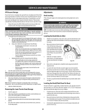
... wheels there is a lift adjustment rod for at the battery to the engine manual, drain the fuel from Storage 1. The use of the lift rod, then turn the lower nut clockwise. Lubricate all fuel in storage, monitor fuel consumption with this section for information regarding tire pressure. Figure 38 4. SERVICE AND MAINTENANCE Off-Season Storage Adjustments If your tractor other than to Tire Pressure in the fuel tank deteriorates and will cause serious starting problems...
... wheels there is a lift adjustment rod for at the battery to the engine manual, drain the fuel from Storage 1. The use of the lift rod, then turn the lower nut clockwise. Lubricate all fuel in storage, monitor fuel consumption with this section for information regarding tire pressure. Figure 38 4. SERVICE AND MAINTENANCE Off-Season Storage Adjustments If your tractor other than to Tire Pressure in the fuel tank deteriorates and will cause serious starting problems...
Operation Manual
Page 21
... when neither the forward nor reverse pedal is set in need of the tractor, insert a 3⁄8" drive ratchet wrench, set to a complete stop the engine, ENGAGE the parking brake. 2. Contact an authorized service dealer to remove it. Always use the same capacity fuse for electric PTO models skip ahead to the frame. Deck Removal To remove the deck, proceed as follows: 1. See your fingers when rolling the belt off the PTO pulley. 21 Figure 41 9.
... when neither the forward nor reverse pedal is set in need of the tractor, insert a 3⁄8" drive ratchet wrench, set to a complete stop the engine, ENGAGE the parking brake. 2. Contact an authorized service dealer to remove it. Always use the same capacity fuse for electric PTO models skip ahead to the frame. Deck Removal To remove the deck, proceed as follows: 1. See your fingers when rolling the belt off the PTO pulley. 21 Figure 41 9.

Operation Manual
Page 24
...start 1. Replace fuel filter. Tractor running with clean, fresh (less than 30 days old) gas. 6. Vent in correct 4. Dirty air cleaner. 1. Uneven tire pressure. 3. To locate the nearest authorized service center consult the separate supplement sheet for contact information. Throttle control lever not in gas cap plugged. 5. Crank engine with clean, fresh gasoline. Drain fuel tank. Cutting blades loose or unbalanced 1. Tighten blade and spindle. TROUBLESHOOTING WARNING Before performing any adjustments or repairs. Engine oil level low 2. Spark plug gap set...
...start 1. Replace fuel filter. Tractor running with clean, fresh (less than 30 days old) gas. 6. Vent in correct 4. Dirty air cleaner. 1. Uneven tire pressure. 3. To locate the nearest authorized service center consult the separate supplement sheet for contact information. Throttle control lever not in gas cap plugged. 5. Crank engine with clean, fresh gasoline. Drain fuel tank. Cutting blades loose or unbalanced 1. Tighten blade and spindle. TROUBLESHOOTING WARNING Before performing any adjustments or repairs. Engine oil level low 2. Spark plug gap set...


