Owners Manual
Page 6
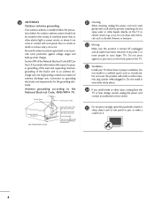
... Section 810-21) Ground Clamps Power Service Grounding Electrode System (NEC Art 250, Part H) 21 Cleaning When cleaning, unplug the power cord and scrub gently with respect to proper grounding of the mast and supporting structure, grounding of the lead-in the vicinity of antenna discharge unit, connection to carry larger TVs. Do not install in a confined space such as...
... Section 810-21) Ground Clamps Power Service Grounding Electrode System (NEC Art 250, Part H) 21 Cleaning When cleaning, unplug the power cord and scrub gently with respect to proper grounding of the mast and supporting structure, grounding of the lead-in the vicinity of antenna discharge unit, connection to carry larger TVs. Do not install in a confined space such as...

Owners Manual
Page 7
...PC) Mode only 70 Manual Configure 71 Selecting XGA Mode 72 Initializing (Reset to a Desk 17 Stand Installation 18 VESA Wall Mounting 19 Desktop Pedestal Installation 19 Antenna or Cable Connection 20 EXTERNAL EQUIPMENT SETUP HD Receiver Setup 21 DVD Setup 24 VCR Setup 26 Other A/V Source Setup 28 Digital Audio Output 28 PC Setup 29 WATCHING TV / CHANNEL CONTROL Remote Control Functions 32 Turning On TV 34 Channel Selection 34 Volume Adjustment 34 On-Screen Menus Selection 35 Channel Setup 36 - Channel Editing 38 DTV Signal Strength 39 Channel Label 40 PICTURE CONTROL...
...PC) Mode only 70 Manual Configure 71 Selecting XGA Mode 72 Initializing (Reset to a Desk 17 Stand Installation 18 VESA Wall Mounting 19 Desktop Pedestal Installation 19 Antenna or Cable Connection 20 EXTERNAL EQUIPMENT SETUP HD Receiver Setup 21 DVD Setup 24 VCR Setup 26 Other A/V Source Setup 28 Digital Audio Output 28 PC Setup 29 WATCHING TV / CHANNEL CONTROL Remote Control Functions 32 Turning On TV 34 Channel Selection 34 Volume Adjustment 34 On-Screen Menus Selection 35 Channel Setup 36 - Channel Editing 38 DTV Signal Strength 39 Channel Label 40 PICTURE CONTROL...

Owners Manual
Page 12
... Button MENU Button ENTER Button VOLUME Buttons CHANNEL Buttons 42PG60C, 42PG65C Stand (Only 42PG65C model) Remote Control Sensor POWER Button Power/Standby Indicator Illuminates red in standby mode. INPUT ENTER Illuminates blue when the set is switched on . INPUT MENU ENTER VOL CH INPUT MENU ENTER VOL CH INPUT MENU ENTER VOL CH INPUT Button MENU Button ENTER Button VOLUME (-,+) Buttons CHANNEL (E, D) Buttons 10 INPUT MENU ENTER VOL CH Remote Control Sensor Power/Standby Indicator Illuminates red when the TV is sold, separately. Illuminates green...
... Button MENU Button ENTER Button VOLUME Buttons CHANNEL Buttons 42PG60C, 42PG65C Stand (Only 42PG65C model) Remote Control Sensor POWER Button Power/Standby Indicator Illuminates red in standby mode. INPUT ENTER Illuminates blue when the set is switched on . INPUT MENU ENTER VOL CH INPUT MENU ENTER VOL CH INPUT MENU ENTER VOL CH INPUT Button MENU Button ENTER Button VOLUME (-,+) Buttons CHANNEL (E, D) Buttons 10 INPUT MENU ENTER VOL CH Remote Control Sensor Power/Standby Indicator Illuminates red when the TV is sold, separately. Illuminates green...

Owners Manual
Page 14
... This part mainly use picture for the LCD TV models. ANTENNA IN M.P.I. 12 13 PREPARATION 1 HDMI/DVI IN 1(DVI) 2 DIGITAL AUDIO OUT (OPTICAL) 2 3 M.P.I 4 RESET/UPDATE/REMOTE CONTROL OUT 5 SERVICE ONLY 6 RGB IN (PC) Connect the output from various types of equipment. AUDIO IN (RGB, DVI) Connect the audio from a PC or DTV. 7 SPEAKER OUT 8Ω 8 AV (Audio/Video) IN Connect audio/video output from your TV. Caution: Never attempt to operate the TV on DC power. 12 ANTENNA IN Connect over-the air signals to these...
... This part mainly use picture for the LCD TV models. ANTENNA IN M.P.I. 12 13 PREPARATION 1 HDMI/DVI IN 1(DVI) 2 DIGITAL AUDIO OUT (OPTICAL) 2 3 M.P.I 4 RESET/UPDATE/REMOTE CONTROL OUT 5 SERVICE ONLY 6 RGB IN (PC) Connect the output from various types of equipment. AUDIO IN (RGB, DVI) Connect the audio from a PC or DTV. 7 SPEAKER OUT 8Ω 8 AV (Audio/Video) IN Connect audio/video output from your TV. Caution: Never attempt to operate the TV on DC power. 12 ANTENNA IN Connect over-the air signals to these...

Owners Manual
Page 21
... models. 4 inches 4 inches 4 inches 4 inches CAUTION G Ensure adequate ventilation by following the clearance recommendations. 19 DESKTOP PEDESTAL INSTALLATION For proper ventilation, allow a clearance of 4inches on the wall mount used. For further information, refer to the VESA Wall Mounting Instruction Guide. A B Product LCD TV Model 32LC5DC*, 32LC50C*, 32LX5DC*, 32LX50C* 32/37/42LC5DC*, 32/37/42LC50C*, 42LB5DC, 42LB50C PLASMA TV 42PG60C 42PX8DC VESA (A * B) 200 * 100 600 * 400 400 * 400 600 * 400 NOTE G Screw...
... models. 4 inches 4 inches 4 inches 4 inches CAUTION G Ensure adequate ventilation by following the clearance recommendations. 19 DESKTOP PEDESTAL INSTALLATION For proper ventilation, allow a clearance of 4inches on the wall mount used. For further information, refer to the VESA Wall Mounting Instruction Guide. A B Product LCD TV Model 32LC5DC*, 32LC50C*, 32LX5DC*, 32LX50C* 32/37/42LC5DC*, 32/37/42LC50C*, 42LB5DC, 42LB50C PLASMA TV 42PG60C 42PX8DC VESA (A * B) 200 * 100 600 * 400 400 * 400 600 * 400 NOTE G Screw...
Owners Manual
Page 23
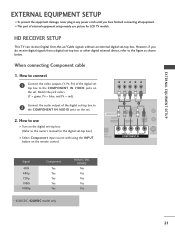
...How to connect 1 Connect the video outputs (Y, PB, PR) of external equipment setup mainly use ■ Turn on the remote control. When connecting Component cable 1. How to use picture for the digital set -top box. EXTERNAL EQUIPMENT SETUP EXTERNAL EQUIPMENT SETUP ■ To prevent the equipment damage, never plug in any power cords until you do receive digital signals from a digital set-top box or other digital external device, refer to the owner's manual for LCD TV models. HD RECEIVER SETUP This TV can receive Digital Over-the-air/Cable signals without an external digital set...
...How to connect 1 Connect the video outputs (Y, PB, PR) of external equipment setup mainly use ■ Turn on the remote control. When connecting Component cable 1. How to use picture for the digital set -top box. EXTERNAL EQUIPMENT SETUP EXTERNAL EQUIPMENT SETUP ■ To prevent the equipment damage, never plug in any power cords until you do receive digital signals from a digital set-top box or other digital external device, refer to the owner's manual for LCD TV models. HD RECEIVER SETUP This TV can receive Digital Over-the-air/Cable signals without an external digital set...
Owners Manual
Page 24
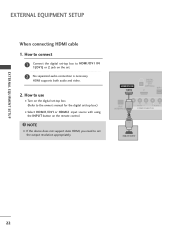
...How to connect 1 Connect the digital set-top box to set . 2 No separated audio connection is necessary. HDMI/DVI IN 1(DVI) DIGITAL AUDIO OUT (OPTICAL) 2 M.P.I RJP INTERFACE 1 VIDEO AUDIO COMPONENT IN HDMI-DTV OUTPUT ( ) 22 HDMI supports both audio and video. 2. How to use ■ Turn on the digital set-top box. ( ) (Refer to the owner's manual for the digital set-top box.) ■ Select HDMI1/DVI or HDMI2 input source with using the INPUT button on the set the output resolution appropriately. EXTERNAL EQUIPMENT SETUP EXTERNAL EQUIPMENT SETUP When connecting HDMI cable...
...How to connect 1 Connect the digital set-top box to set . 2 No separated audio connection is necessary. HDMI/DVI IN 1(DVI) DIGITAL AUDIO OUT (OPTICAL) 2 M.P.I RJP INTERFACE 1 VIDEO AUDIO COMPONENT IN HDMI-DTV OUTPUT ( ) 22 HDMI supports both audio and video. 2. How to use ■ Turn on the digital set-top box. ( ) (Refer to the owner's manual for the digital set-top box.) ■ Select HDMI1/DVI or HDMI2 input source with using the INPUT button on the set the output resolution appropriately. EXTERNAL EQUIPMENT SETUP EXTERNAL EQUIPMENT SETUP When connecting HDMI cable...
Owners Manual
Page 25
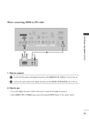
... HDMI/DVI IN 1(DVI) or 2 jack on the remote control. 23 How to use ■ Turn on the digital set-top box. (Refer to the AUDIO IN (RGB,DVI) jack on the set -top box.) ■ Select HDMI1/DVI or HDMI2 input source with using the INPUT button on the set. 2 Connect the audio output of the digital set-top box to the owner's manual for the digital set . 2. EXTERNAL EQUIPMENT SETUP When connecting HDMI to DVI cable HDMI/DVI IN 1(DVI) DIGITAL AUDIO OUT (OPTICAL...
... HDMI/DVI IN 1(DVI) or 2 jack on the remote control. 23 How to use ■ Turn on the digital set-top box. (Refer to the AUDIO IN (RGB,DVI) jack on the set -top box.) ■ Select HDMI1/DVI or HDMI2 input source with using the INPUT button on the set. 2 Connect the audio output of the digital set-top box to the owner's manual for the digital set . 2. EXTERNAL EQUIPMENT SETUP When connecting HDMI to DVI cable HDMI/DVI IN 1(DVI) DIGITAL AUDIO OUT (OPTICAL...

Owners Manual
Page 26
... picture quality, connect a DVD player to the DVD player's manual for operating instructions. Y PB PR L R Connect the audio outputs of the DVD to use ■ Turn on the remote control. ■ Refer to the component input ports as shown below. EXTERNAL EQUIPMENT SETUP EXTERNAL EQUIPMENT SETUP DVD SETUP When connecting Component cable 1. How to the COMPONENT IN VIDEO jacks on DVD player Y Y PB PR PB PR B-Y R-Y Cb Cr Pb Pr 24 Component ports on the TV Y Y Video output ports Y on the set . 2. Match the jack colors (Y = green, PB = blue, and PR = red...
... picture quality, connect a DVD player to the DVD player's manual for operating instructions. Y PB PR L R Connect the audio outputs of the DVD to use ■ Turn on the remote control. ■ Refer to the component input ports as shown below. EXTERNAL EQUIPMENT SETUP EXTERNAL EQUIPMENT SETUP DVD SETUP When connecting Component cable 1. How to the COMPONENT IN VIDEO jacks on DVD player Y Y PB PR PB PR B-Y R-Y Cb Cr Pb Pr 24 Component ports on the TV Y Y Video output ports Y on the set . 2. Match the jack colors (Y = green, PB = blue, and PR = red...

Owners Manual
Page 27
... DVD player's manual for operating instructions. How to use HDMI/DVI IN 1(DVI) DIGITAL AUDIO OUT (OPTICAL) 2 M.P.I . HDMI-DVD OUTPUT 25 RJP INTERFACE VIDEO AUDIO COMPONENT IN 1 NOTE G If the device does not support Auto HDMI, you need to the S -VIDEO input on the set . 2. How to use ■ Turn on the DVD player, insert a DVD. ■ Select A V 1 input source with using the INPUT button on the set . 2 No separated audio connection is necessary. S REMOTE CONTROL UPDATE OUT AUDIO NT IN S-VIDEO (MONO) AUDIO AV IN 1 VIDEO SPE O When connecting HDMI cable...
... DVD player's manual for operating instructions. How to use HDMI/DVI IN 1(DVI) DIGITAL AUDIO OUT (OPTICAL) 2 M.P.I . HDMI-DVD OUTPUT 25 RJP INTERFACE VIDEO AUDIO COMPONENT IN 1 NOTE G If the device does not support Auto HDMI, you need to the S -VIDEO input on the set . 2. How to use ■ Turn on the DVD player, insert a DVD. ■ Select A V 1 input source with using the INPUT button on the set . 2 No separated audio connection is necessary. S REMOTE CONTROL UPDATE OUT AUDIO NT IN S-VIDEO (MONO) AUDIO AV IN 1 VIDEO SPE O When connecting HDMI cable...

Owners Manual
Page 29
... the VCR owner's manual.) ■ Select A V 1 input source with using the INPUT button on the remote control. ■ If connected to the VCR owner's manual.) ■ Select A V 1 input source with a RCA cable ANT IN S-VIDEO L R VIDEO EXTERNAL EQUIPMENT SETUP 1. ( ) When connecting with using the INPUT button on the set . 1. How to AV IN2, select A V 2 input source. RESET UPDATE 1 REMOTE CONTROL OUT SERV R AUDIO T IN S-VIDEO (MONO) AUDIO AV IN 1 VIDEO SPEAKE OUT 8 NOTE G If you connect both Video and S-Video at the same time. NOTE G The picture quality is...
... the VCR owner's manual.) ■ Select A V 1 input source with using the INPUT button on the remote control. ■ If connected to the VCR owner's manual.) ■ Select A V 1 input source with a RCA cable ANT IN S-VIDEO L R VIDEO EXTERNAL EQUIPMENT SETUP 1. ( ) When connecting with using the INPUT button on the set . 1. How to AV IN2, select A V 2 input source. RESET UPDATE 1 REMOTE CONTROL OUT SERV R AUDIO T IN S-VIDEO (MONO) AUDIO AV IN 1 VIDEO SPEAKE OUT 8 NOTE G If you connect both Video and S-Video at the same time. NOTE G The picture quality is...

Owners Manual
Page 30
... cable to the digital audio (optical) input on the remote control. ■ If connected to use ■ Select A V 2 input source with external audio equipments, such as amplifiers or speakers, please turn the TV speakers off. (G p.58) CAUTION G Do not look into the optical output port. How to external audio equipment via the Digital Audio Output (Optical) port. 1. Match the jack colors. (Video = yellow, Audio Left = white, and Audio Right = red) Camcorder Video Game Set VIDEO L R 2. See the external audio equipment instruction manual for operation. EXTERNAL EQUIPMENT SETUP...
... cable to the digital audio (optical) input on the remote control. ■ If connected to use ■ Select A V 2 input source with external audio equipments, such as amplifiers or speakers, please turn the TV speakers off. (G p.58) CAUTION G Do not look into the optical output port. How to external audio equipment via the Digital Audio Output (Optical) port. 1. Match the jack colors. (Video = yellow, Audio Left = white, and Audio Right = red) Camcorder Video Game Set VIDEO L R 2. See the external audio equipment instruction manual for operation. EXTERNAL EQUIPMENT SETUP...

Owners Manual
Page 31
... OUTPUT AUDIO 29 RGB IN ( ) ( ) RJP INTERFACE VIDEO ER AUDIO COMPONENT IN (RGB, DVI) 2. How to connect SERVICE ONLY REMOTE CONTROL ATE OUT ( ) ( ) RGB IN 1 Connect the RGB output of the PC to DVI cable RGB OUTPUT AUDIO 1. When connecting D-sub 15pin cable 1. HDMI/DVI IN 1(DVI) DIGITA AUDIO OUT (OPTICA VICE ONLY 2 Connect the PC audio output to the AUDIO IN 2 (RGB, DVI) jack on the set . EXTERNAL EQUIPMENT SETUP PC SETUP This TV provides Plug and Play...
... OUTPUT AUDIO 29 RGB IN ( ) ( ) RJP INTERFACE VIDEO ER AUDIO COMPONENT IN (RGB, DVI) 2. How to connect SERVICE ONLY REMOTE CONTROL ATE OUT ( ) ( ) RGB IN 1 Connect the RGB output of the PC to DVI cable RGB OUTPUT AUDIO 1. When connecting D-sub 15pin cable 1. HDMI/DVI IN 1(DVI) DIGITA AUDIO OUT (OPTICA VICE ONLY 2 Connect the PC audio output to the AUDIO IN 2 (RGB, DVI) jack on the set . EXTERNAL EQUIPMENT SETUP PC SETUP This TV provides Plug and Play...
Owners Manual
Page 32
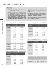
... not work if a HDMI to another rate or adjust the brightness and contrast on your TV. G Avoid keeping a fixed image on the screen for Horizontal and Vertical frequencies is in use. G The synchronization input form for a long period of the PC graphic card can not be noise associated with the resolution, vertical pattern, contrast or brightness in HDMI1-PC mode. EXTERNAL EQUIPMENT SETUP Supported Display Specifications...
... not work if a HDMI to another rate or adjust the brightness and contrast on your TV. G Avoid keeping a fixed image on the screen for Horizontal and Vertical frequencies is in use. G The synchronization input form for a long period of the PC graphic card can not be noise associated with the resolution, vertical pattern, contrast or brightness in HDMI1-PC mode. EXTERNAL EQUIPMENT SETUP Supported Display Specifications...

Owners Manual
Page 34
POWER Turns your TV or any other programmed equipment on or off mode. Changes the PIP channel. G p.42 VCR/DVD Control video cassette recorders or DVD players. TV INPUT In AV 1-2, Component, RGB, HDMI1/DVI, and HDMI2 input sources, screen returns to enter a program number for multiple program channels such as 2-1, 2-2, etc. G p.41-42 PIP CH +/- G p.41 Selects the factory preset picture depend on mode. control buttons NUMBER button - (DASH) Used to the last TV channel. FLASH BACK Tune to the last channel viewed. MULTI Selects: RGB,HDMI1...
POWER Turns your TV or any other programmed equipment on or off mode. Changes the PIP channel. G p.42 VCR/DVD Control video cassette recorders or DVD players. TV INPUT In AV 1-2, Component, RGB, HDMI1/DVI, and HDMI2 input sources, screen returns to enter a program number for multiple program channels such as 2-1, 2-2, etc. G p.41-42 PIP CH +/- G p.41 Selects the factory preset picture depend on mode. control buttons NUMBER button - (DASH) Used to the last TV channel. FLASH BACK Tune to the last channel viewed. MULTI Selects: RGB,HDMI1...

Owners Manual
Page 35
... WATCHING TV / CHANNEL CONTROL PIP SAP PIP CH- INFO Display information at the top of screen information to the next one full set - (Up/Down/Left /Right/ENTER) tings to preserve environment. 33 PIP CH + PIP INPUT EZ PIC EZ SOUND SWAP INFO CC EXIT MENU RATIO SAP ENTER VOL TIMER MUTE CH PAGE 1 2 3 remote control INPUT TV POWER MODE TV INPUT DVD MULTI VCR PIP PIP CH - PIP CH+ PIP SWAP PIP INPUT Installing Batteries Remote control effective range 32/37/42LC5DC...
... WATCHING TV / CHANNEL CONTROL PIP SAP PIP CH- INFO Display information at the top of screen information to the next one full set - (Up/Down/Left /Right/ENTER) tings to preserve environment. 33 PIP CH + PIP INPUT EZ PIC EZ SOUND SWAP INFO CC EXIT MENU RATIO SAP ENTER VOL TIMER MUTE CH PAGE 1 2 3 remote control INPUT TV POWER MODE TV INPUT DVD MULTI VCR PIP PIP CH - PIP CH+ PIP SWAP PIP INPUT Installing Batteries Remote control effective range 32/37/42LC5DC...

Owners Manual
Page 37
.... Block Downloadable Rating SCREEN SETUP VIDEO AUDIO TIME OPTION SCREEN LOCK Auto config. or button to display the SETUP SETUP VIDEO AUDIO TIME OPTION SCREEN LOCK EZ Scan Manual Scan Channel Edit DTV Signal Channel Label VIDEO SETUP VIDEO AUDIO TIME OPTION SCREEN LOCK EZ Picture Color Temperature XD Advanced Reset AUDIO SETUP Audio Language VIDEO EZ SoundRite AUDIO EZ Sound TIME Balance 0 OPTION TV Speakers SCREEN LOCK WATCHING TV / CHANNEL CONTROL LOCK For USA SETUP VIDEO AUDIO TIME OPTION SCREEN LOCK Lock System Set Password Block Channel Movie Rating TV Rating...
.... Block Downloadable Rating SCREEN SETUP VIDEO AUDIO TIME OPTION SCREEN LOCK Auto config. or button to display the SETUP SETUP VIDEO AUDIO TIME OPTION SCREEN LOCK EZ Scan Manual Scan Channel Edit DTV Signal Channel Label VIDEO SETUP VIDEO AUDIO TIME OPTION SCREEN LOCK EZ Picture Color Temperature XD Advanced Reset AUDIO SETUP Audio Language VIDEO EZ SoundRite AUDIO EZ Sound TIME Balance 0 OPTION TV Speakers SCREEN LOCK WATCHING TV / CHANNEL CONTROL LOCK For USA SETUP VIDEO AUDIO TIME OPTION SCREEN LOCK Lock System Set Password Block Channel Movie Rating TV Rating...
Owners Manual
Page 76
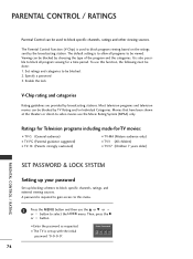
.... To use this menu. 1 Press the MENU button and then use the Movie Rating System (MPAA) only. EntEenrtPear sPsawssowrdord ** ** 74 Set ratings and categories to select the LOCK menu. Most television programs and television movies can be blocked. 2. The Parental Control Function (V-Chip) is to block specific channels, ratings and other viewing sources. Specify a password 3. The default setting is used to allow all program viewing for -TV movies: ■ TV-G (General audience) ■ TV-PG (Parental guidance...
.... To use this menu. 1 Press the MENU button and then use the Movie Rating System (MPAA) only. EntEenrtPear sPsawssowrdord ** ** 74 Set ratings and categories to select the LOCK menu. Most television programs and television movies can be blocked. 2. The Parental Control Function (V-Chip) is to block specific channels, ratings and other viewing sources. Specify a password 3. The default setting is used to allow all program viewing for -TV movies: ■ TV-G (General audience) ■ TV-PG (Parental guidance...

Owners Manual
Page 78
... a screen filled with channel numbers and a preview picture. 3 Use D E F G or button to select a channel and then use the D or E or or button to choose Aux. Block Downloadable Rating For Canada Lock System Set Password Block Channel TV Rating-English TV Rating-French Aux. Block Downloadable Rating SETUP VIDEO AUDIO TIME OPTION SCREEN LOCK Lock System Set Password Block Channel Movie Rating TV Rating-Children TV Rating-General Aux. ing or press MENU button to return to TV view- PARENTAL CONTROL / RATING 1 After inputting the password, use the ENTER button...
... a screen filled with channel numbers and a preview picture. 3 Use D E F G or button to select a channel and then use the D or E or or button to choose Aux. Block Downloadable Rating For Canada Lock System Set Password Block Channel TV Rating-English TV Rating-French Aux. Block Downloadable Rating SETUP VIDEO AUDIO TIME OPTION SCREEN LOCK Lock System Set Password Block Channel Movie Rating TV Rating-Children TV Rating-General Aux. ing or press MENU button to return to TV view- PARENTAL CONTROL / RATING 1 After inputting the password, use the ENTER button...
Owners Manual
Page 86
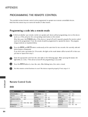
... seconds; Note that , press the POWER button. The programming procedures are explained below. 2 Press the MENU and MUTE button continuously at a time. If the device turned off . the currently selected device button is successful. 4 Press the MENU button to repeat from step 2. 3 Enter the appropriate code from the code table on the following pages. APPENDIX Remote Control Code DVD Brand Codes Brand APEX DIGITAL 022 DENON 020 014 GE...
... seconds; Note that , press the POWER button. The programming procedures are explained below. 2 Press the MENU and MUTE button continuously at a time. If the device turned off . the currently selected device button is successful. 4 Press the MENU button to repeat from step 2. 3 Enter the appropriate code from the code table on the following pages. APPENDIX Remote Control Code DVD Brand Codes Brand APEX DIGITAL 022 DENON 020 014 GE...


