
Owners Manual
Page 7
... 19 Antenna or Cable Connection 20 EXTERNAL EQUIPMENT SETUP HD Receiver Setup 21 DVD Setup 24 VCR Setup 26 Other A/V Source Setup 28 Digital Audio Output 28 PC Setup 29 WATCHING TV / CHANNEL CONTROL Remote Control Functions 32 Turning On TV 34 Channel Selection 34 Volume Adjustment 34 On-... Cover for Wire Arrangement 13 Attaching the TV to a Wall 16 Swivel Stand 16 Attaching the TV to Original Factory Settings) . 73 PARENTAL CONTROL / RATINGS Set Password & Lock System 74 - User Mode 47 Color Tone - Add / Delete Channel (Manual Scan 37 - Preset 45 - EZ Picture - ...
... 19 Antenna or Cable Connection 20 EXTERNAL EQUIPMENT SETUP HD Receiver Setup 21 DVD Setup 24 VCR Setup 26 Other A/V Source Setup 28 Digital Audio Output 28 PC Setup 29 WATCHING TV / CHANNEL CONTROL Remote Control Functions 32 Turning On TV 34 Channel Selection 34 Volume Adjustment 34 On-... Cover for Wire Arrangement 13 Attaching the TV to a Wall 16 Swivel Stand 16 Attaching the TV to Original Factory Settings) . 73 PARENTAL CONTROL / RATINGS Set Password & Lock System 74 - User Mode 47 Color Tone - Add / Delete Channel (Manual Scan 37 - Preset 45 - EZ Picture - ...

Owners Manual
Page 8
... SAP PIP INPUT 9 FLASHBK VOL TIMER MUTE 1 4 2 7 5 3 8 6 CH PAGE 0 9 BAFCLKASH 1.5V 1.5V Owner's Manual, Setup & Operation Guide for Commercial Mode CD Manual Remote Control, Batteries Power Cord * Slightly wipe stained spot on surface of the exterior. may be visible...not wipe roughly when removing stain. Avoid touching the LCD screen or holding your local authority. b. LCD TV PLASMA TV Owner's Manual http://www.lgusa.com www.lg.ca Copyright© 2007 LGE, All Rights Reserved. TV UT INPUT MULTI POWER TMVODE VOL EZRPAICTPSIIOPTEBTZ SVOPUIPNDCH -...
... SAP PIP INPUT 9 FLASHBK VOL TIMER MUTE 1 4 2 7 5 3 8 6 CH PAGE 0 9 BAFCLKASH 1.5V 1.5V Owner's Manual, Setup & Operation Guide for Commercial Mode CD Manual Remote Control, Batteries Power Cord * Slightly wipe stained spot on surface of the exterior. may be visible...not wipe roughly when removing stain. Avoid touching the LCD screen or holding your local authority. b. LCD TV PLASMA TV Owner's Manual http://www.lgusa.com www.lg.ca Copyright© 2007 LGE, All Rights Reserved. TV UT INPUT MULTI POWER TMVODE VOL EZRPAICTPSIIOPTEBTZ SVOPUIPNDCH -...

Owners Manual
Page 15
It will help prevent the power cable from your TV. (This feature is dropped, you may be injured or the product may be damaged. To connect an additional equipment, see the EXTERNAL EQUIPMENT SETUP section. CABLE MANAGEMENT 13 PREPARATION BACK COVER FOR WIRE ARRANGEMENT ■ Here shown may be somewhat different from being...
It will help prevent the power cable from your TV. (This feature is dropped, you may be injured or the product may be damaged. To connect an additional equipment, see the EXTERNAL EQUIPMENT SETUP section. CABLE MANAGEMENT 13 PREPARATION BACK COVER FOR WIRE ARRANGEMENT ■ Here shown may be somewhat different from being...

Owners Manual
Page 16
PREPARATION PREPARATION BACK COVER FOR WIRE ARRANGEMENT ■ Here shown may be somewhat different from being removed by accident. 3 Install the CABLE HOLDER as necessary. It will help prevent the power cable from your TV. (This feature is not available for all models.) 1 To separate the CABLE HOLDER, loosen the bolt installed the set. 2 Connect the cables as shown. To connect an additional equipment, see the EXTERNAL EQUIPMENT SETUP section. PROTECTIVE BRACKET BOLT CABLE HOLDER 14 Secure the power cable with the PROTECTIVE BRACKET and the screw as shown.
PREPARATION PREPARATION BACK COVER FOR WIRE ARRANGEMENT ■ Here shown may be somewhat different from being removed by accident. 3 Install the CABLE HOLDER as necessary. It will help prevent the power cable from your TV. (This feature is not available for all models.) 1 To separate the CABLE HOLDER, loosen the bolt installed the set. 2 Connect the cables as shown. To connect an additional equipment, see the EXTERNAL EQUIPMENT SETUP section. PROTECTIVE BRACKET BOLT CABLE HOLDER 14 Secure the power cable with the PROTECTIVE BRACKET and the screw as shown.

Owners Manual
Page 17
To connect additional equipment, see the EXTERNAL EQUIPMENT SETUP section. 2 Install the CABLE MANAGEMENT CLIP as shown. (Except 42PG60C model) If your TV has CABLE HOLDER, fix it as shown and bundle the cables. 3 Install the CABLE MANAGEMENT as necessary. Hold the CABLE MANAGEMENT CLIP ...the product may be broken. 15 To connect an additional equipment, see the EXTERNAL EQUIPMENT SETUP section. 45° 2 Connect the cables as shown. NOTE G Do not hold the CABLE MANAGEMENT CLIP when moving the TV. - CABLE MANAGEMENT CLIP CABLE HOLDER How to remove the CABLE MANAGEMENT CLIP (Except ...
To connect additional equipment, see the EXTERNAL EQUIPMENT SETUP section. 2 Install the CABLE MANAGEMENT CLIP as shown. (Except 42PG60C model) If your TV has CABLE HOLDER, fix it as shown and bundle the cables. 3 Install the CABLE MANAGEMENT as necessary. Hold the CABLE MANAGEMENT CLIP ...the product may be broken. 15 To connect an additional equipment, see the EXTERNAL EQUIPMENT SETUP section. 45° 2 Connect the cables as shown. NOTE G Do not hold the CABLE MANAGEMENT CLIP when moving the TV. - CABLE MANAGEMENT CLIP CABLE HOLDER How to remove the CABLE MANAGEMENT CLIP (Except ...
Owners Manual
Page 23
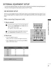
However, if you have finished connecting all equipment. ■ This part of external equipment setup mainly use ■ Turn on the digital set-top box. (Refer to the owner's manual for LCD TV models. How to connect 1 Connect the video outputs (Y, PB, PR) of the digital set-top box to...refer to 2 the COMPONENT IN AUDIO jacks on the set -top box. HD RECEIVER SETUP This TV can receive Digital Over-the-air/Cable signals without an external digital set . EXTERNAL EQUIPMENT SETUP EXTERNAL EQUIPMENT SETUP ■ To prevent the equipment damage, never plug in any power cords until you do...
However, if you have finished connecting all equipment. ■ This part of external equipment setup mainly use ■ Turn on the digital set-top box. (Refer to the owner's manual for LCD TV models. How to connect 1 Connect the video outputs (Y, PB, PR) of the digital set-top box to...refer to 2 the COMPONENT IN AUDIO jacks on the set -top box. HD RECEIVER SETUP This TV can receive Digital Over-the-air/Cable signals without an external digital set . EXTERNAL EQUIPMENT SETUP EXTERNAL EQUIPMENT SETUP ■ To prevent the equipment damage, never plug in any power cords until you do...
Owners Manual
Page 24
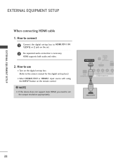
.../DVI IN 1(DVI) DIGITAL AUDIO OUT (OPTICAL) 2 M.P.I RJP INTERFACE 1 VIDEO AUDIO COMPONENT IN HDMI-DTV OUTPUT ( ) 22 HDMI supports both audio and video. 2. EXTERNAL EQUIPMENT SETUP EXTERNAL EQUIPMENT SETUP When connecting HDMI cable 1.
.../DVI IN 1(DVI) DIGITAL AUDIO OUT (OPTICAL) 2 M.P.I RJP INTERFACE 1 VIDEO AUDIO COMPONENT IN HDMI-DTV OUTPUT ( ) 22 HDMI supports both audio and video. 2. EXTERNAL EQUIPMENT SETUP EXTERNAL EQUIPMENT SETUP When connecting HDMI cable 1.
Owners Manual
Page 25
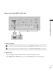
... RGB IN RJP INTERFACE 1 VIDEO AUDIO COMPONENT IN S-VIDEO (MONO) AUDIO AV IN 1 VIDEO SPEAKER AUDIO OUT IN 8 (RGB, DVI) 2 DVI-DTV OUTPUT L R 1. EXTERNAL EQUIPMENT SETUP When connecting HDMI to the AUDIO IN (RGB,DVI) jack on the remote control. 23
... RGB IN RJP INTERFACE 1 VIDEO AUDIO COMPONENT IN S-VIDEO (MONO) AUDIO AV IN 1 VIDEO SPEAKER AUDIO OUT IN 8 (RGB, DVI) 2 DVI-DTV OUTPUT L R 1. EXTERNAL EQUIPMENT SETUP When connecting HDMI to the AUDIO IN (RGB,DVI) jack on the remote control. 23

Owners Manual
Page 26
EXTERNAL EQUIPMENT SETUP EXTERNAL EQUIPMENT SETUP DVD SETUP When connecting Component cable 1. Match the jack colors (Y = green, PB = blue, and PR = red). Y PB PR L R Connect the audio outputs of the DVD to the 2 ... the set . 2. How to use ■ Turn on the remote control. ■ Refer to the component input ports as shown below. Component ports on the TV Y Y Video output ports Y on the set .
EXTERNAL EQUIPMENT SETUP EXTERNAL EQUIPMENT SETUP DVD SETUP When connecting Component cable 1. Match the jack colors (Y = green, PB = blue, and PR = red). Y PB PR L R Connect the audio outputs of the DVD to the 2 ... the set . 2. How to use ■ Turn on the remote control. ■ Refer to the component input ports as shown below. Component ports on the TV Y Y Video output ports Y on the set .

Owners Manual
Page 27
... OUT AUDIO NT IN S-VIDEO (MONO) AUDIO AV IN 1 VIDEO SPE O When connecting HDMI cable 1. HDMI supports both audio and video. 2. S-VIDEO AUDIO L R EXTERNAL EQUIPMENT SETUP 2 Connect the audio outputs of the DVD to the S -VIDEO input on the set . How to use ■ Turn on the DVD player, insert a DVD...
... OUT AUDIO NT IN S-VIDEO (MONO) AUDIO AV IN 1 VIDEO SPE O When connecting HDMI cable 1. HDMI supports both audio and video. 2. S-VIDEO AUDIO L R EXTERNAL EQUIPMENT SETUP 2 Connect the audio outputs of the DVD to the S -VIDEO input on the set . How to use ■ Turn on the DVD player, insert a DVD...

Owners Manual
Page 28
... socket of the VCR to the Antenna socket on the screen for a long period of time. (Only Plasma TV model). How to use ■ Set VCR output switch to 3 or 4 and then tune TV to the same channel number. ■ Insert a video tape into the VCR and press PLAY on the VCR... RF antenna in socket of the screen may remain visible on the sides of the VCR. 2. EXTERNAL EQUIPMENT SETUP EXTERNAL EQUIPMENT SETUP VCR SETUP ■ To avoid picture noise (interference), leave an adequate distance between the VCR and TV. ■ Use the ISM feature in the Option menu to the VCR owner's manual.) 26
... socket of the VCR to the Antenna socket on the screen for a long period of time. (Only Plasma TV model). How to use ■ Set VCR output switch to 3 or 4 and then tune TV to the same channel number. ■ Insert a video tape into the VCR and press PLAY on the VCR... RF antenna in socket of the screen may remain visible on the sides of the VCR. 2. EXTERNAL EQUIPMENT SETUP EXTERNAL EQUIPMENT SETUP VCR SETUP ■ To avoid picture noise (interference), leave an adequate distance between the VCR and TV. ■ Use the ISM feature in the Option menu to the VCR owner's manual.) 26

Owners Manual
Page 29
..., select A V 2 input source. AUDIO ENT IN S-VIDEO (MONO) AUDIO AV IN 1 VIDEO SPEAK OUT 8 ■ If connected to connect 1 Connect the AUDIO/VIDEO jacks between TV and VCR. How to the AUDIO input jacks on the set. CAUTION G Do not connect to connect M.P.I . 2. In the event that you have a mono VCR... . 1. NOTE G The picture quality is improved: compared to the VCR owner's manual.) ■ Select A V 1 input source with a RCA cable ANT IN S-VIDEO L R VIDEO EXTERNAL EQUIPMENT SETUP 1.
..., select A V 2 input source. AUDIO ENT IN S-VIDEO (MONO) AUDIO AV IN 1 VIDEO SPEAK OUT 8 ■ If connected to connect 1 Connect the AUDIO/VIDEO jacks between TV and VCR. How to the AUDIO input jacks on the set. CAUTION G Do not connect to connect M.P.I . 2. In the event that you have a mono VCR... . 1. NOTE G The picture quality is improved: compared to the VCR owner's manual.) ■ Select A V 1 input source with a RCA cable ANT IN S-VIDEO L R VIDEO EXTERNAL EQUIPMENT SETUP 1.

Owners Manual
Page 30
S-VIDEO 1 VIDEO L/MONO AUDIO R AV IN 2 DIGITAL AUDIO OUTPUT i.e) 32/37/42LC5DC*, 32/37/42LC50C*, 42LB5DC, 42LB50C Send the TV's audio to connect 1 Connect the AUDIO/VIDEO jacks between TV and external equipment. HDMI/DVI IN 1(DVI) DIGITAL AUDIO OUT (OPTICAL) 2 M.P.I. 1 ( RJP VIDEO AUDIO S-V ...operation. Off" in the AUDIO menu. (G p.58). Looking at the laser beam may damage your vision. 28 EXTERNAL EQUIPMENT SETUP EXTERNAL EQUIPMENT SETUP OTHER A/V SOURCE SETUP 1. How to AV IN1 input, select A V 1 input source. ■ Operate the corresponding external equipment. How to...
S-VIDEO 1 VIDEO L/MONO AUDIO R AV IN 2 DIGITAL AUDIO OUTPUT i.e) 32/37/42LC5DC*, 32/37/42LC50C*, 42LB5DC, 42LB50C Send the TV's audio to connect 1 Connect the AUDIO/VIDEO jacks between TV and external equipment. HDMI/DVI IN 1(DVI) DIGITAL AUDIO OUT (OPTICAL) 2 M.P.I. 1 ( RJP VIDEO AUDIO S-V ...operation. Off" in the AUDIO menu. (G p.58). Looking at the laser beam may damage your vision. 28 EXTERNAL EQUIPMENT SETUP EXTERNAL EQUIPMENT SETUP OTHER A/V SOURCE SETUP 1. How to AV IN1 input, select A V 1 input source. ■ Operate the corresponding external equipment. How to...

Owners Manual
Page 31
...the set . ■ Select RGB-PC input source with using the INPUT button on the remote control. 2 1 When connecting HDMI to the TV's settings. DVI-PC OUTPUT AUDIO 29 How to connect SERVICE ONLY REMOTE CONTROL ATE OUT ( ) ( ) RGB IN 1 Connect the RGB output... ) 1 ■ Turn on the remote control. RGB IN ( ) ( ) RJP INTERFACE VIDEO ER AUDIO COMPONENT IN (RGB, DVI) 2. EXTERNAL EQUIPMENT SETUP PC SETUP This TV provides Plug and Play capability, meaning that the PC adjusts automatically to DVI cable RGB OUTPUT AUDIO 1. When connecting D-sub 15pin cable 1.
...the set . ■ Select RGB-PC input source with using the INPUT button on the remote control. 2 1 When connecting HDMI to the TV's settings. DVI-PC OUTPUT AUDIO 29 How to connect SERVICE ONLY REMOTE CONTROL ATE OUT ( ) ( ) RGB IN 1 Connect the RGB output... ) 1 ■ Turn on the remote control. RGB IN ( ) ( ) RJP INTERFACE VIDEO ER AUDIO COMPONENT IN (RGB, DVI) 2. EXTERNAL EQUIPMENT SETUP PC SETUP This TV provides Plug and Play capability, meaning that the PC adjusts automatically to DVI cable RGB OUTPUT AUDIO 1. When connecting D-sub 15pin cable 1.
Owners Manual
Page 32
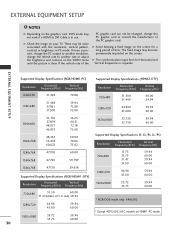
If noise is separate. The fixed image may become permanently imprinted on your TV. G The synchronization input form for a long period of time. G Avoid keeping a fixed image on the ....500 31.469 60.00 59.94 1280x720 44.960 45.000 59.94 60.00 800x600 1024x768 35.156 37.879 48.077 46.875 48.363 56.476 60.023 56.25 60.31 72.18 75.00 60.... PC graphic card can not be noise associated with the resolution, vertical pattern, contrast or brightness in PC mode. EXTERNAL EQUIPMENT SETUP NOTES G Depending on the graphics card, DOS mode may not work if a HDMI to DVI Cable is clear. G Check...
If noise is separate. The fixed image may become permanently imprinted on your TV. G The synchronization input form for a long period of time. G Avoid keeping a fixed image on the ....500 31.469 60.00 59.94 1280x720 44.960 45.000 59.94 60.00 800x600 1024x768 35.156 37.879 48.077 46.875 48.363 56.476 60.023 56.25 60.31 72.18 75.00 60.... PC graphic card can not be noise associated with the resolution, vertical pattern, contrast or brightness in PC mode. EXTERNAL EQUIPMENT SETUP NOTES G Depending on the graphics card, DOS mode may not work if a HDMI to DVI Cable is clear. G Check...

Owners Manual
Page 33
EXTERNAL EQUIPMENT SETUP * 42LB5DC, 42LB50C Supported Display Specifications (RGB/HDMI1-PC) Resolution 640x350 (RGB only) Horizontal Vertical Frequency(KHz) Frequency(Hz) 31.469 70.08 640x480 31.469 37.861 37.500 59.94 72.80 75.00 Supported Display Specifications (HDMI2-DTV) Resolution Horizontal Vertical Frequency(KHz) Frequency(Hz) 720x480 31.500 31....469 60.00 59.94 1280x720 44.960 45.000 59.94 60.00 800x600 35.156 37.879 48.077 46.875 56.25 60.31 72.18 75.00 1920x1080 33.720 33.750 67.500 59.94 60.00 60...
EXTERNAL EQUIPMENT SETUP * 42LB5DC, 42LB50C Supported Display Specifications (RGB/HDMI1-PC) Resolution 640x350 (RGB only) Horizontal Vertical Frequency(KHz) Frequency(Hz) 31.469 70.08 640x480 31.469 37.861 37.500 59.94 72.80 75.00 Supported Display Specifications (HDMI2-DTV) Resolution Horizontal Vertical Frequency(KHz) Frequency(Hz) 720x480 31.500 31....469 60.00 59.94 1280x720 44.960 45.000 59.94 60.00 800x600 35.156 37.879 48.077 46.875 56.25 60.31 72.18 75.00 1920x1080 33.720 33.750 67.500 59.94 60.00 60...

Owners Manual
Page 37
... VIDEO EZ SoundRite AUDIO EZ Sound TIME Balance 0 OPTION TV Speakers SCREEN LOCK WATCHING TV / CHANNEL CONTROL LOCK For USA SETUP VIDEO AUDIO TIME OPTION SCREEN LOCK Lock System Set Password Block Channel Movie Rating TV Rating-Children TV Rating-General Aux. Block Downloadable Rating SCREEN SETUP VIDEO AUDIO TIME OPTION SCREEN LOCK Auto config. button...
... VIDEO EZ SoundRite AUDIO EZ Sound TIME Balance 0 OPTION TV Speakers SCREEN LOCK WATCHING TV / CHANNEL CONTROL LOCK For USA SETUP VIDEO AUDIO TIME OPTION SCREEN LOCK Lock System Set Password Block Channel Movie Rating TV Rating-Children TV Rating-General Aux. Block Downloadable Rating SCREEN SETUP VIDEO AUDIO TIME OPTION SCREEN LOCK Auto config. button...

Owners Manual
Page 38
... AUDIO TIME OPTION SCREEN LOCK EZ Scan Manual Scan Channel Edit DTV Signal Channel Label G Processing EZ scan... WATCHING TV / CHANNEL CONTROL WATCHING TV /CHANNEL CONTROL CHANNEL SETUP Auto Scan (EZ Scan) Automatically finds all channels available through antenna or cable inputs, and stores them in memory... on . 1 Press the MENU button and then use D or E or or button to select the SETUP menu. 2 Press the G or ...
... AUDIO TIME OPTION SCREEN LOCK EZ Scan Manual Scan Channel Edit DTV Signal Channel Label G Processing EZ scan... WATCHING TV / CHANNEL CONTROL WATCHING TV /CHANNEL CONTROL CHANNEL SETUP Auto Scan (EZ Scan) Automatically finds all channels available through antenna or cable inputs, and stores them in memory... on . 1 Press the MENU button and then use D or E or or button to select the SETUP menu. 2 Press the G or ...

Owners Manual
Page 39
.... 5 Press the ENTER button to add or delete the channel. 6 Press the EXIT or RETURN button to return to TV viewing or press MENU button to return to delete the channel. 345 37 SETUP VIDEO AUDIO TIME OPTION SCREEN LOCK EZ Scan Manual Scan Channel Edit DTV Signal Channel Label... 1 SETUP VIDEO AUDIO TIME OPTION SCREEN LOCK EZ Scan Manual Scan Channel Edit DTV Signal Channel Label G Channel Type Number ANALOG 2 SETUP VIDEO AUDIO TIME OPTION SCREEN LOCK...
.... 5 Press the ENTER button to add or delete the channel. 6 Press the EXIT or RETURN button to return to TV viewing or press MENU button to return to delete the channel. 345 37 SETUP VIDEO AUDIO TIME OPTION SCREEN LOCK EZ Scan Manual Scan Channel Edit DTV Signal Channel Label... 1 SETUP VIDEO AUDIO TIME OPTION SCREEN LOCK EZ Scan Manual Scan Channel Edit DTV Signal Channel Label G Channel Type Number ANALOG 2 SETUP VIDEO AUDIO TIME OPTION SCREEN LOCK...

Owners Manual
Page 40
WATCHING TV /CHANNEL CONTROL WATCHING TV / CHANNEL CONTROL Channel Editing A Custom List can add or delete the channel by toggling each channel on . 1 Press the MENU button and then use D or E or or button to select the SETUP menu. 2 Press the G or button and then use D or E or or button to select Channel Edit... ENTER button to add or delete it. 5 Press EXIT or RETURN button to return to TV viewing or press MENU button to return to the small window at the top-left corner of the screen. SETUP VIDEO AUDIO TIME OPTION SCREEN LOCK EZ Scan Manual Scan Channel Edit DTV Signal Channel Label...
WATCHING TV /CHANNEL CONTROL WATCHING TV / CHANNEL CONTROL Channel Editing A Custom List can add or delete the channel by toggling each channel on . 1 Press the MENU button and then use D or E or or button to select the SETUP menu. 2 Press the G or button and then use D or E or or button to select Channel Edit... ENTER button to add or delete it. 5 Press EXIT or RETURN button to return to TV viewing or press MENU button to return to the small window at the top-left corner of the screen. SETUP VIDEO AUDIO TIME OPTION SCREEN LOCK EZ Scan Manual Scan Channel Edit DTV Signal Channel Label...

