
MTF Product Data Sheet
Page 1
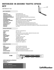
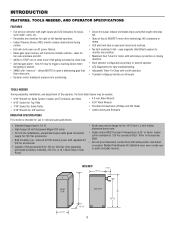
... MTF SECTION 34 71 00 KEY FEATURES PRODUCT TYPE In-ground flush mount STANDARD APPLICATION Multi-directional traffic control INSTALLATION APPLICATIONS Commercial, industrial, security/military SPIKE MAINTENANCE ACCESSIBILITY Top-down modular design for easy service and maintenance TOOTH DESIGN Aggressive tooth SPIKE RETURN SYSTEM Reliable counter-balanced system, low maintenance operation FIRE DEPARTMENT COMPLIANCE Auto-open /close POWER 120V/230V single phase ACCESSORY POWER 24VDC 500 mA output GEAR...
... MTF SECTION 34 71 00 KEY FEATURES PRODUCT TYPE In-ground flush mount STANDARD APPLICATION Multi-directional traffic control INSTALLATION APPLICATIONS Commercial, industrial, security/military SPIKE MAINTENANCE ACCESSIBILITY Top-down modular design for easy service and maintenance TOOTH DESIGN Aggressive tooth SPIKE RETURN SYSTEM Reliable counter-balanced system, low maintenance operation FIRE DEPARTMENT COMPLIANCE Auto-open /close POWER 120V/230V single phase ACCESSORY POWER 24VDC 500 mA output GEAR...
MTF Product Guide
Page 1
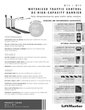
... is used. LED BARRIER ARM Aluminum arm with sensor that turns on both sides. DUAL-GATE OPERATION WORKS IN CONJUNCTION WITH ANOTHER BARRIER OPERATOR. LIFTMASTER LOOP DETECTOR Automatic sensitivity settings and power efficient to maximize operator's RELIABLE battery backup operations. FIRE DEPARTMENT COMPLIANCE ALLOWS GATE TO AUTO-OPEN UPON LOSS OF AC POWER OR BATTERY DEPLETION. WARRANTY 2 YEARS OPENER AND TRAFFIC SPIKE SYSTEM. 10 YEARS OPENER CABINET. UNIVERSAL CONTROLLER WITH 8 INPUTS ALLOWS FOR THE CONNECTION OF A FULL RANGE...
... is used. LED BARRIER ARM Aluminum arm with sensor that turns on both sides. DUAL-GATE OPERATION WORKS IN CONJUNCTION WITH ANOTHER BARRIER OPERATOR. LIFTMASTER LOOP DETECTOR Automatic sensitivity settings and power efficient to maximize operator's RELIABLE battery backup operations. FIRE DEPARTMENT COMPLIANCE ALLOWS GATE TO AUTO-OPEN UPON LOSS OF AC POWER OR BATTERY DEPLETION. WARRANTY 2 YEARS OPENER AND TRAFFIC SPIKE SYSTEM. 10 YEARS OPENER CABINET. UNIVERSAL CONTROLLER WITH 8 INPUTS ALLOWS FOR THE CONNECTION OF A FULL RANGE...

MTF Product Guide
Page 4
... MTF MOTORIZED TRAFFIC CONTROL SURFACE MOUNT FLUSH MOUNT For Support Tools and Training Videos, Visit L i f t M a s t e r Tr a i n i n g . ARTICULATED ARM © 2018 LiftMaster. STANDARD SPECS. - LOAD RATING: 36,000 LBS. Per Single Axle Load. - c o m / U L 3 2 5 G AT E S L i f t M a s t e r D e a l e r. CONSTRUCTION -Gear Reduction: 60:1 Reducer in Synthetic Oil Bath. -Motor: 1/2 Hp Equivalent Continuous-Duty 24VDC/800 RPM. -Operator Cabinet: Powder Coated 1/4" Aluminum Alloy. -Spike Assembly: Red Powder Coat Painted 1/4" Steel Construction. ADDITIONAL OPTIONS. - ACCESSORY POWER...
... MTF MOTORIZED TRAFFIC CONTROL SURFACE MOUNT FLUSH MOUNT For Support Tools and Training Videos, Visit L i f t M a s t e r Tr a i n i n g . ARTICULATED ARM © 2018 LiftMaster. STANDARD SPECS. - LOAD RATING: 36,000 LBS. Per Single Axle Load. - c o m / U L 3 2 5 G AT E S L i f t M a s t e r D e a l e r. CONSTRUCTION -Gear Reduction: 60:1 Reducer in Synthetic Oil Bath. -Motor: 1/2 Hp Equivalent Continuous-Duty 24VDC/800 RPM. -Operator Cabinet: Powder Coated 1/4" Aluminum Alloy. -Spike Assembly: Red Powder Coat Painted 1/4" Steel Construction. ADDITIONAL OPTIONS. - ACCESSORY POWER...
Installation Manual
Page 2
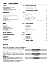
... Motorized Traffic Control Base and Extensions Attach the Operator to the Base Install the Barrier Arm 7-9 ADDITIONAL FEATURES 21-24 7 Suggested Loop Sensor Locations 21 7 Trap Instructions 22 9 Sequence Access Management System (SAMS) with "Memory" 23 9 Control Board Layout and Input Locations 24 WIRING 10-13 TROUBLESHOOTING 25 Earth Ground Rod 10 Battery Checkout 25 Power Wiring 10 Gate Not Operating 25 Inputs (J5 Terminal Strip) 11 Accessory and Relay Connections 12 REPAIR PARTS 25 Battery Installation...
... Motorized Traffic Control Base and Extensions Attach the Operator to the Base Install the Barrier Arm 7-9 ADDITIONAL FEATURES 21-24 7 Suggested Loop Sensor Locations 21 7 Trap Instructions 22 9 Sequence Access Management System (SAMS) with "Memory" 23 9 Control Board Layout and Input Locations 24 WIRING 10-13 TROUBLESHOOTING 25 Earth Ground Rod 10 Battery Checkout 25 Power Wiring 10 Gate Not Operating 25 Inputs (J5 Terminal Strip) 11 Accessory and Relay Connections 12 REPAIR PARTS 25 Battery Installation...

Installation Manual
Page 4
... end-use . 9. Locate the gate such that enough clearance is supplied between the sensor and the gate operator is intended for exposed rollers. 5. Vehicular gate systems provide convenience and security. All openings of a vehicular vertical lift gate. Swinging gates shall not open position. b. d. Improperly designed, installed or maintained systems can create high levels of force in its arc of travel of many component parts. SAFETY SAFETY INSTALLATION INFORMATION 1. e. The Stop and/or Reset...
... end-use . 9. Locate the gate such that enough clearance is supplied between the sensor and the gate operator is intended for exposed rollers. 5. Vehicular gate systems provide convenience and security. All openings of a vehicular vertical lift gate. Swinging gates shall not open position. b. d. Improperly designed, installed or maintained systems can create high levels of force in its arc of travel of many component parts. SAFETY SAFETY INSTALLATION INFORMATION 1. e. The Stop and/or Reset...
Installation Manual
Page 5
... the use of these installation instructions will result in broken or bent teeth, broken springs, correct direction tire damage, inability to receive the maximum performance from improper installation or use the Lighted Warning Sign. Replacement parts needed in order for repairing malfunctions or replacing parts resulting from improper installation or use and maintenance of the area (Warning Sign Model 14115 [lighted] or 14150 [reflective]). • Use caution when installing near...
... the use of these installation instructions will result in broken or bent teeth, broken springs, correct direction tire damage, inability to receive the maximum performance from improper installation or use the Lighted Warning Sign. Replacement parts needed in order for repairing malfunctions or replacing parts resulting from improper installation or use and maintenance of the area (Warning Sign Model 14115 [lighted] or 14150 [reflective]). • Use caution when installing near...
Installation Manual
Page 6
... close loop. • Anti-tail gate alarm - inherent 24 Vdc backup power with eight inputs and LED indicators for loops, card reader, radio, etc. • Reversible arm direction for right or left handed operation. • Instant Reverse Device (IRD) monitor senses obstructions during motion. • Fail safe (auto open a slide/swing gate first then raises arm. • Dynamic motor braking to preserve arm positioning. • Direct drive gear reducer eliminates many parts...
... close loop. • Anti-tail gate alarm - inherent 24 Vdc backup power with eight inputs and LED indicators for loops, card reader, radio, etc. • Reversible arm direction for right or left handed operation. • Instant Reverse Device (IRD) monitor senses obstructions during motion. • Fail safe (auto open a slide/swing gate first then raises arm. • Dynamic motor braking to preserve arm positioning. • Direct drive gear reducer eliminates many parts...
Installation Manual
Page 7
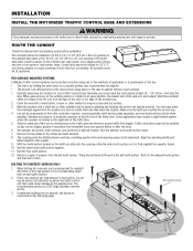
... traveled way. 2. Mark the location with a chalk line or other method to an open position, the closest part of the gate arm and support shall have a lateral offset of at least 2 feet (61 cm) from the last tooth section. Carefully determine the location for loop sensor leads. Tunnel 3/8" Concrete Anchor Epoxy area 7 Tooth section End bevel INSTALLATION INSTALL THE MOTORIZED TRAFFIC CONTROL BASE AND EXTENSIONS...
... traveled way. 2. Mark the location with a chalk line or other method to an open position, the closest part of the gate arm and support shall have a lateral offset of at least 2 feet (61 cm) from the last tooth section. Carefully determine the location for loop sensor leads. Tunnel 3/8" Concrete Anchor Epoxy area 7 Tooth section End bevel INSTALLATION INSTALL THE MOTORIZED TRAFFIC CONTROL BASE AND EXTENSIONS...

Installation Manual
Page 10
... properly the range of the remote controls will be reduced and the operator will need to be purchased for 230 Vac operation. NOTE: Do not connect the batteries until disconnecting the electrical power and locking-out the power via the operator power switch. Do not connect any wiring or attempt to run in separate conduit. • BEFORE installing power wiring or control stations be sure to follow ALL specifications and warnings...
... properly the range of the remote controls will be reduced and the operator will need to be purchased for 230 Vac operation. NOTE: Do not connect the batteries until disconnecting the electrical power and locking-out the power via the operator power switch. Do not connect any wiring or attempt to run in separate conduit. • BEFORE installing power wiring or control stations be sure to follow ALL specifications and warnings...

Installation Manual
Page 11
... SAFETY 5 CLOSE 6 BACK 7 SHADOW 8 C16 R46 R5Ø R61 11 This input is generally not used its closing motion and not continue to close until the close if closing . They are to be used as receivers, loop detectors, access controls, and push button stations. When input is active, gate will reverse and close immediately once input is to make gate reverse and go back to monitor an auxiliary open , pulse close . SAMS with timed...
... SAFETY 5 CLOSE 6 BACK 7 SHADOW 8 C16 R46 R5Ø R61 11 This input is generally not used its closing motion and not continue to close until the close if closing . They are to be used as receivers, loop detectors, access controls, and push button stations. When input is active, gate will reverse and close immediately once input is to make gate reverse and go back to monitor an auxiliary open , pulse close . SAMS with timed...

Installation Manual
Page 12
... detector, radio receiver. Relay will fire when arm is pushed up off of the control board at J4 terminals 1 and 2. Relay will pulse relay when arm reaches full open position. Connect AC power BEFORE installing batteries. 2. maximum). BAT+ 24VAC XFM 24 Vdc (+) 0 Vdc (-) The K1 Relay (optional) and terminal strip (J1) are located at the bottom of limit switch (use with slip clutch option) and fires relay when a tail-gate is not closed. installing batteries. 1. Replace batteries in...
... detector, radio receiver. Relay will fire when arm is pushed up off of the control board at J4 terminals 1 and 2. Relay will pulse relay when arm reaches full open position. Connect AC power BEFORE installing batteries. 2. maximum). BAT+ 24VAC XFM 24 Vdc (+) 0 Vdc (-) The K1 Relay (optional) and terminal strip (J1) are located at the bottom of limit switch (use with slip clutch option) and fires relay when a tail-gate is not closed. installing batteries. 1. Replace batteries in...

Installation Manual
Page 14
...keep gate or garage door in transformer, or power provided from a moving gate or door. NOTE: The receiver will blink 3 times. LEDs SINGLE CHANNEL Receiver Single Operator(s) CH1 CH3 CH2 INSTALLATION The receiver and antenna use of children. When the channel has reached full capacity for specific wiring information. NEVER permit anyone to program a button on a commercial door operator. The receiver is PROHIBITED. To prevent possible SERIOUS INJURY or DEATH from your commercial door operator or gate operator owner manual or wiring diagrams for keypads, all LEDs will...
...keep gate or garage door in transformer, or power provided from a moving gate or door. NOTE: The receiver will blink 3 times. LEDs SINGLE CHANNEL Receiver Single Operator(s) CH1 CH3 CH2 INSTALLATION The receiver and antenna use of children. When the channel has reached full capacity for specific wiring information. NEVER permit anyone to program a button on a commercial door operator. The receiver is PROHIBITED. To prevent possible SERIOUS INJURY or DEATH from your commercial door operator or gate operator owner manual or wiring diagrams for keypads, all LEDs will...

Installation Manual
Page 15
...: If your commercial door operator or gate operator wiring diagrams for instructions on the receiver blinks, then turns off ; adjustment or modifications of the FCC rules and IC RSS-210. THERE ARE NO USER SERVICEABLE PARTS. TO ERASE THE MEMORY 1 Press and hold the button on the remote control that you wish to program to the receiver. 3 Release the remote control button when the LED on connecting two or more 3-Button control devices. PROGRAMMING PROGRAM A SINGLE BUTTON REMOTE CONTROL 1 Press and release the Learn button for the...
...: If your commercial door operator or gate operator wiring diagrams for instructions on the receiver blinks, then turns off ; adjustment or modifications of the FCC rules and IC RSS-210. THERE ARE NO USER SERVICEABLE PARTS. TO ERASE THE MEMORY 1 Press and hold the button on the remote control that you wish to program to the receiver. 3 Release the remote control button when the LED on connecting two or more 3-Button control devices. PROGRAMMING PROGRAM A SINGLE BUTTON REMOTE CONTROL 1 Press and release the Learn button for the...

Installation Manual
Page 16
... TIMER) DIP Switch S1-1 to S1-4 When the gate operator activates, it is controlled by reversing the factory default motor connections. Connect power to the ON position. 4. When DIP switches S1-1, S1-2 and S1-3 are set to 2-3/8 seconds by facing the control board with the barrier arm in the ON position, the Single Button Function (Command to Open/Command to the arm and just behind the limit sensor. 6. When S1-8 DIP switch...
... TIMER) DIP Switch S1-1 to S1-4 When the gate operator activates, it is controlled by reversing the factory default motor connections. Connect power to the ON position. 4. When DIP switches S1-1, S1-2 and S1-3 are set to 2-3/8 seconds by facing the control board with the barrier arm in the ON position, the Single Button Function (Command to Open/Command to the arm and just behind the limit sensor. 6. When S1-8 DIP switch...
Installation Manual
Page 18
... circuit that continuously monitors the motor's current for the limit cam to travel , retest the gate operator. Ensure the limit cam set at S-2 switches 1-5) and then close . KEEP GATES PROPERLY MAINTAINED. Read the owner's manual. NO ONE SHOULD CROSS THE PATH OF THE MOVING GATE. 7. If the gate stops while opening , the arm will stop when an object activates the non-contact sensors. Use the emergency release ONLY when the gate is TOO sensitive. ADJUST...
... circuit that continuously monitors the motor's current for the limit cam to travel , retest the gate operator. Ensure the limit cam set at S-2 switches 1-5) and then close . KEEP GATES PROPERLY MAINTAINED. Read the owner's manual. NO ONE SHOULD CROSS THE PATH OF THE MOVING GATE. 7. If the gate stops while opening , the arm will stop when an object activates the non-contact sensors. Use the emergency release ONLY when the gate is TOO sensitive. ADJUST...
Installation Manual
Page 19
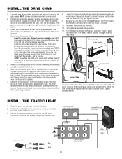
... set screws. The light is keyed to be adjusted by loosening the two set screws. From the service side, the teeth sections extends to your LEFT: Use supplied master link kit to the left or right along the shaft. Tighten allen/set screw (picture). Position the traffic light on the system. Reed Switch Black Black LED lights red when switch is lowered. Manually spin the MAT pulley to remaining threaded shaft To lower sprocket using...
... set screws. The light is keyed to be adjusted by loosening the two set screws. From the service side, the teeth sections extends to your LEFT: Use supplied master link kit to the left or right along the shaft. Tighten allen/set screw (picture). Position the traffic light on the system. Reed Switch Black Black LED lights red when switch is lowered. Manually spin the MAT pulley to remaining threaded shaft To lower sprocket using...

Installation Manual
Page 20
... PIN REPLACEMENT If gate arm is recommended that support motor to put gate into collar. 7. Turn the S3 Manual Open switch to OPEN on the control board to rotate gate arm bracket to ensure proper and safe operation, it must be done by always punching out the pin (or pieces) from electrocution, disconnect ALL electric power BEFORE performing ANY maintenance. Reinstall the barrier arm if required. 9. Connect AC power and batteries. 10. Shear Pin Collar (Operator) Gate Arm Bracket Barrier Arm BATTERY BATTERY DISPOSAL Replaced batteries must...
... PIN REPLACEMENT If gate arm is recommended that support motor to put gate into collar. 7. Turn the S3 Manual Open switch to OPEN on the control board to rotate gate arm bracket to ensure proper and safe operation, it must be done by always punching out the pin (or pieces) from electrocution, disconnect ALL electric power BEFORE performing ANY maintenance. Reinstall the barrier arm if required. 9. Connect AC power and batteries. 10. Shear Pin Collar (Operator) Gate Arm Bracket Barrier Arm BATTERY BATTERY DISPOSAL Replaced batteries must...

Installation Manual
Page 22
... the battery terminal. 2. Set switch bank S2 to the OPEN input (J5 - The trap gate will close and the second gate should close loop on the trap operator. Reconnect the DC power by replacing the neutral (Black) wire to the common of the trap operator to the operator. 3. ADDITIONAL FEATURES TRAP INSTRUCTIONS INSTALL THE K1 AUXILIARY RELAY AND CONNECTOR AT MATTS CONNECTED TO THE ACCESS DEVICE 1. RECONNECT THE POWER AND TEST 1. INSTALL...
... the battery terminal. 2. Set switch bank S2 to the OPEN input (J5 - The trap gate will close and the second gate should close loop on the trap operator. Reconnect the DC power by replacing the neutral (Black) wire to the common of the trap operator to the operator. 3. ADDITIONAL FEATURES TRAP INSTRUCTIONS INSTALL THE K1 AUXILIARY RELAY AND CONNECTOR AT MATTS CONNECTED TO THE ACCESS DEVICE 1. RECONNECT THE POWER AND TEST 1. INSTALL...

Installation Manual
Page 23
... this mode, if the arm senses an impact, the K1 relay will stay energized holding open signal was stored in memory) to raise again if it to raise if one of its full open limit switch, this will allow the SAMS feature to work with the other operator's safety loops, safety edges and reverse sensors WILL NOT cause the arm to open limit switch. This will keep the other gate operator locked open...
... this mode, if the arm senses an impact, the K1 relay will stay energized holding open signal was stored in memory) to raise again if it to raise if one of its full open limit switch, this will allow the SAMS feature to work with the other operator's safety loops, safety edges and reverse sensors WILL NOT cause the arm to open limit switch. This will keep the other gate operator locked open...
Installation Manual
Page 26
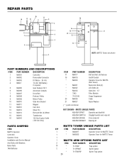
... Trap option MATTS UNIQUE PARTS K99-ENF-SPRKT Sprocket and shaft kit K99-ENF-SWITCH Stoplight switch and relay kit K99-ENF-DRCHN Drive chain kit K99-ENF-BRNGKT Bearing kit PARTS SHIPPED ITEM MATTS Operator Controller Operator Cover Installation and Service Manual Arm Bolts with Washers Nylon Nuts 7AH Batteries MATTS TOWER UNIQUE PARTS LIST QTY ITEM PART NUMBER DESCRIPTION 1 * MA020T Operator Cover for MATTS Tower 1 * MA020D Operator Door for MATTS (Not Tower) Nylon Arm Nuts (2) Arm Bolts (2) Gate Arm - 12' Filter Module...
... Trap option MATTS UNIQUE PARTS K99-ENF-SPRKT Sprocket and shaft kit K99-ENF-SWITCH Stoplight switch and relay kit K99-ENF-DRCHN Drive chain kit K99-ENF-BRNGKT Bearing kit PARTS SHIPPED ITEM MATTS Operator Controller Operator Cover Installation and Service Manual Arm Bolts with Washers Nylon Nuts 7AH Batteries MATTS TOWER UNIQUE PARTS LIST QTY ITEM PART NUMBER DESCRIPTION 1 * MA020T Operator Cover for MATTS Tower 1 * MA020D Operator Door for MATTS (Not Tower) Nylon Arm Nuts (2) Arm Bolts (2) Gate Arm - 12' Filter Module...


