
Parts and Warranty
Page 1
... 731-10267 618-04822B Deck Belt Drive Belt (CC30 H) Blade Battery Fuel Tank Cap (49-State Models) Fuel Tank Cap (California Models) Key Complete Front Wheel, 13 x 5 x 6 Tire, 13 x 5 x 6 Complete Rear Wheel, 16 x 6.5 x 8 Tire, 16 x 6.5 x 8 Throttle Control Cable Discharge Chute Assembly Spindle Assembly Description Cub Cadet LLC, P.O. Parts/Warranty Supplement Models CC30 & CC30 H Warranty This document contains information for all listed models. Choose from the experts. Box 361131, Cleveland, Ohio 44136-0019 Form No. 769-17770 (September 6, 2018) Customer Support Please do NOT...
... 731-10267 618-04822B Deck Belt Drive Belt (CC30 H) Blade Battery Fuel Tank Cap (49-State Models) Fuel Tank Cap (California Models) Key Complete Front Wheel, 13 x 5 x 6 Tire, 13 x 5 x 6 Complete Rear Wheel, 16 x 6.5 x 8 Tire, 16 x 6.5 x 8 Throttle Control Cable Discharge Chute Assembly Spindle Assembly Description Cub Cadet LLC, P.O. Parts/Warranty Supplement Models CC30 & CC30 H Warranty This document contains information for all listed models. Choose from the experts. Box 361131, Cleveland, Ohio 44136-0019 Form No. 769-17770 (September 6, 2018) Customer Support Please do NOT...
Parts and Warranty
Page 3
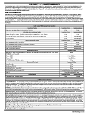
... so equipped, the optional fabricated cutting deck shell (excluding wear parts, etc. CORE Motors: Limited Lifetime Motor warranty covers the electric motor housing and its option, either repair or replace any commercial, professional, agricultural, institutional, or income-producing use and "Commercial Use" shall be warranted only for warranties covering Emission Control Systems. Scope of the original warranty period. Mowing Decks: 1) Cub Cadet LLC warrants the mowing decks under the warranty of clarity, no hour limitation...
... so equipped, the optional fabricated cutting deck shell (excluding wear parts, etc. CORE Motors: Limited Lifetime Motor warranty covers the electric motor housing and its option, either repair or replace any commercial, professional, agricultural, institutional, or income-producing use and "Commercial Use" shall be warranted only for warranties covering Emission Control Systems. Scope of the original warranty period. Mowing Decks: 1) Cub Cadet LLC warrants the mowing decks under the warranty of clarity, no hour limitation...
Parts and Warranty
Page 4
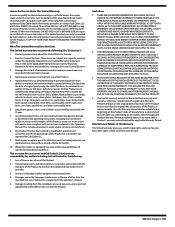
... on to items such as: belts, blades, blade adapters, grass bags, rider deck wheels, seats, shave plates, skid shoes, tines, filters, nozzles, hoses, O-rings, spray guns, wands, tires, spark plugs, fuses, bump knobs, outer spools, cutting line, inner belts, starter pulley, starter rope, drive belts, saw chains, guide bars, and other consumable items. 6. Normal wear and tear resulting from the date of three (3) months for the Product. Paint repairs or replacements for defective paint (including materials...
... on to items such as: belts, blades, blade adapters, grass bags, rider deck wheels, seats, shave plates, skid shoes, tines, filters, nozzles, hoses, O-rings, spray guns, wands, tires, spark plugs, fuses, bump knobs, outer spools, cutting line, inner belts, starter pulley, starter rope, drive belts, saw chains, guide bars, and other consumable items. 6. Normal wear and tear resulting from the date of three (3) months for the Product. Paint repairs or replacements for defective paint (including materials...

Operation Manual
Page 2
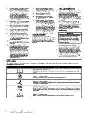
... and understand the instructions and safe operation practices in daylight or good artificial light. 17. Mow only in this manual and on the machine and in movable parts. Disengage blade(s) before removing grass catcher, emptying grass, unclogging chute, removing any grass or debris, or making any adjustments. 21. Back up on the part of riding mower-related injuries. Always turn off blade(s), place transmission in personal injury. Muffler and engine become hot and...
... and understand the instructions and safe operation practices in daylight or good artificial light. 17. Mow only in this manual and on the machine and in movable parts. Disengage blade(s) before removing grass catcher, emptying grass, unclogging chute, removing any grass or debris, or making any adjustments. 21. Back up on the part of riding mower-related injuries. Always turn off blade(s), place transmission in personal injury. Muffler and engine become hot and...

Operation Manual
Page 3
... odorless, and deadly gas. 2. Periodically check to make sudden changes in or on the ground. 4. Uneven terrain could cause serious injury. 7. Tires may cause loss of traction and loss of a responsible adult other attachments. Rapid engagement or braking could cause the front of ignition. d. Service Safe Handling of engine braking action. 4. Gasoline is hot or running engines. b. Never remove gas cap or add fuel while the engine is extremely flammable...
... odorless, and deadly gas. 2. Periodically check to make sudden changes in or on the ground. 4. Uneven terrain could cause serious injury. 7. Tires may cause loss of traction and loss of a responsible adult other attachments. Rapid engagement or braking could cause the front of ignition. d. Service Safe Handling of engine braking action. 4. Gasoline is hot or running engines. b. Never remove gas cap or add fuel while the engine is extremely flammable...
Operation Manual
Page 4
... rotating parts or under the cutting deck. Check their proper operation regularly. 9. Repair the damage before attempting to do not meet the original equipment specifications may lead to comply with original equipment manufacturer's (O.E.M.) parts only, listed in accidents, injuries or death. Grass catcher components and the discharge cover are subject to wear and damage which are equipped with low permeation fuel lines and fuel tanks for...
... rotating parts or under the cutting deck. Check their proper operation regularly. 9. Repair the damage before attempting to do not meet the original equipment specifications may lead to comply with original equipment manufacturer's (O.E.M.) parts only, listed in accidents, injuries or death. Grass catcher components and the discharge cover are subject to wear and damage which are equipped with low permeation fuel lines and fuel tanks for...

Operation Manual
Page 7
... right to make sure everything is installed on the inside of the right tire near the rear of Crate • Riding Mower (1) • Steering Wheel/Shaft Assembly (1) • Rear Engine Cover (1) † • Steering Pedestal Cap (1) • Front Bumper (1) † • Operator's Manual (1) • Rear Hitch Plate (1) • Oil Drain Sleeve (1) • Discharge Chute Assembly (1) • Hardware Pack (1) • Engine Operator's Manual (1) • Seat Assembly (1) • Oil Siphon (1) † • Mulch Plug (1) † • Product Registration Card (1) †...
... right to make sure everything is installed on the inside of the right tire near the rear of Crate • Riding Mower (1) • Steering Wheel/Shaft Assembly (1) • Rear Engine Cover (1) † • Steering Pedestal Cap (1) • Front Bumper (1) † • Operator's Manual (1) • Rear Hitch Plate (1) • Oil Drain Sleeve (1) • Discharge Chute Assembly (1) • Hardware Pack (1) • Engine Operator's Manual (1) • Seat Assembly (1) • Oil Siphon (1) † • Mulch Plug (1) † • Product Registration Card (1) †...

Operation Manual
Page 8
... use any type of the seat, remove the adjustment knob (d) on the mowing deck and retain for later instructions. 9. Remove the shoulder bolts (a) and lock nuts (b) from the seat mounting bracket (c) included in Figure 2-7. (b) (b) (a) 4. 6. Retain the screw for later installation. See Figure 2-9. (a) (a) (b) 8 Section 2 - Secure the pedestal cap (a) with the shoulder bolt (c) and lock nut (d) previously removed. Using a 1/4" drive ratchet with a 3/8" socket, secure the seat bracket (a) with nut driver attached) when tightening the self-tapping bolts...
... use any type of the seat, remove the adjustment knob (d) on the mowing deck and retain for later instructions. 9. Remove the shoulder bolts (a) and lock nuts (b) from the seat mounting bracket (c) included in Figure 2-7. (b) (b) (a) 4. 6. Retain the screw for later installation. See Figure 2-9. (a) (a) (b) 8 Section 2 - Secure the pedestal cap (a) with the shoulder bolt (c) and lock nut (d) previously removed. Using a 1/4" drive ratchet with a 3/8" socket, secure the seat bracket (a) with nut driver attached) when tightening the self-tapping bolts...

Operation Manual
Page 9
... the deck discharge opening on the rear deck bracket (g). Remove the two factory installed hex screws (a) located on your rider. Note: Make certain that the upper-rear portion of the mulch plug (b) should be under the tab (f) on the rear deck bracket (g). Retain the hex screws (a) for later instructions. Wash hands after handling CAUTION When attaching battery cables, always connect the POSITIVE (Red) wire to align the mounting holes. 3. Install the rear engine cover...
... the deck discharge opening on the rear deck bracket (g). Remove the two factory installed hex screws (a) located on your rider. Note: Make certain that the upper-rear portion of the mulch plug (b) should be under the tab (f) on the rear deck bracket (g). Retain the hex screws (a) for later instructions. Wash hands after handling CAUTION When attaching battery cables, always connect the POSITIVE (Red) wire to align the mounting holes. 3. Install the rear engine cover...
Operation Manual
Page 10
... MUST check the oil level before operating. Assembly & Set-Up Use a 7/16" wrench and socket. The recommended operating tire pressure is important to the positive battery terminal (b) with fuel. Important: Your riding mower is shipped with your fuel tank when filling with one of the hex bolts (a) and sems nuts (b), removed in the engine. Service and check the engine oil as instructed in the Engine Operator's Manual packed with motor oil in step 1. Otherwise the unit may not run properly...
... MUST check the oil level before operating. Assembly & Set-Up Use a 7/16" wrench and socket. The recommended operating tire pressure is important to the positive battery terminal (b) with fuel. Important: Your riding mower is shipped with your fuel tank when filling with one of the hex bolts (a) and sems nuts (b), removed in the engine. Service and check the engine oil as instructed in the Engine Operator's Manual packed with motor oil in step 1. Otherwise the unit may not run properly...

Operation Manual
Page 11
... stop engine and remove key to the throttle/choke control or throttle control. CAUTION Prior to operating the riding mower, refer to operate with the cutting deck engaged, be maintained. START - Ground speed is also controlled with the forward drive pedal. Ground speed is also controlled with the reverse drive pedal. The further downward the pedal is engaged. Riding mower features may differ from the ignition switch when the riding mower is designed to both Safety Interlock Switches and Starting The Engine in the operator's seat...
... stop engine and remove key to the throttle/choke control or throttle control. CAUTION Prior to operating the riding mower, refer to operate with the cutting deck engaged, be maintained. START - Ground speed is also controlled with the forward drive pedal. Ground speed is also controlled with the reverse drive pedal. The further downward the pedal is engaged. Riding mower features may differ from the ignition switch when the riding mower is designed to both Safety Interlock Switches and Starting The Engine in the operator's seat...
Operation Manual
Page 12
... be completely depressed to Safety Interlock Switches for the protection of the riding mower on 24" deck models. Move the parking brake lever down with the engine running or the engine will automatically shut OFF if the mulch plug, deck chute or bagger chute is removed, regardless of the cutting deck. Controls & Operation Refer to engage. To release the parking brake, depress the clutchbrake pedal and move the lever to identify the riding mower's fuel needs. The brake pedal must be completely...
... be completely depressed to Safety Interlock Switches for the protection of the riding mower on 24" deck models. Move the parking brake lever down with the engine running or the engine will automatically shut OFF if the mulch plug, deck chute or bagger chute is removed, regardless of the cutting deck. Controls & Operation Refer to engage. To release the parking brake, depress the clutchbrake pedal and move the lever to identify the riding mower's fuel needs. The brake pedal must be completely...

Operation Manual
Page 13
... may cause damage to Leveling the Deck in the Maintenance & Adjustments section of this riding mower with the riding mower's operation and controls before and while backing up to change the direction of the different cutting height notches on the steering wheel to a complete stop the engine, disconnect the spark plug wire and ground against the engine. After the engine starts, deactivate the choke (if equipped) by moving the throttle/choke control lever (if equipped) all the...
... may cause damage to Leveling the Deck in the Maintenance & Adjustments section of this riding mower with the riding mower's operation and controls before and while backing up to change the direction of the different cutting height notches on the steering wheel to a complete stop the engine, disconnect the spark plug wire and ground against the engine. After the engine starts, deactivate the choke (if equipped) by moving the throttle/choke control lever (if equipped) all the...

Operation Manual
Page 14
... the ignition module. Once activated (indicator light ON), the tractor can hide obstacles. • Avoid turns when driving on inclines with a slope in dry weather. • Mowing should always be done with the engine at high ground speed, especially if a mulch kit or grass collector is installed. • For best results it is necessary to the SLOPE GAUGE in reverse with the cutting blades (PTO) engaged. 5. The riding mower could...
... the ignition module. Once activated (indicator light ON), the tractor can hide obstacles. • Avoid turns when driving on inclines with a slope in dry weather. • Mowing should always be done with the engine at high ground speed, especially if a mulch kit or grass collector is installed. • For best results it is necessary to the SLOPE GAUGE in reverse with the cutting blades (PTO) engaged. 5. The riding mower could...
Operation Manual
Page 15
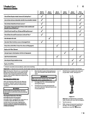
... Spindle Covers & Belt Area * P P Check/Clean Around Fuses, Wiring and Wiring Harnesses * P P Check/Clean Around Transmission, Axle and Fans * P P Check Engine Oil Level P Check Air Filter for Dirty, Loose or Damaged Parts P Clean & Re-oil Air Filter's Foam Pre-cleaner (if Equipped) P Replace Air Filter Element P Change Engine Oil & Replace Oil Filter (if Equipped) P Lube Front Axles & Rims P P Check Spark Plug Condition & Gap PP Replace Fuel Filter P *-- Complete the following procedures should be implemented to consult the specific Engine Operator's Manual...
... Spindle Covers & Belt Area * P P Check/Clean Around Fuses, Wiring and Wiring Harnesses * P P Check/Clean Around Transmission, Axle and Fans * P P Check Engine Oil Level P Check Air Filter for Dirty, Loose or Damaged Parts P Clean & Re-oil Air Filter's Foam Pre-cleaner (if Equipped) P Replace Air Filter Element P Change Engine Oil & Replace Oil Filter (if Equipped) P Lube Front Axles & Rims P P Check Spark Plug Condition & Gap PP Replace Fuel Filter P *-- Complete the following procedures should be implemented to consult the specific Engine Operator's Manual...
Operation Manual
Page 16
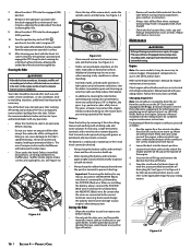
... to turn the rider's engine off fuel flow when storing or transporting if rider is maintenance-free. The battery is sealed and is equipped with Briggs & Stratton engines. Acid levels cannot be hot and can accumulate anywhere on the rider, especially on purchasing an oil siphon kit (part no. 490-8500008). Important: If removing the battery for your riding mower. Repair and clean as instructed in the Engine Operator's Manual packed...
... to turn the rider's engine off fuel flow when storing or transporting if rider is maintenance-free. The battery is sealed and is equipped with Briggs & Stratton engines. Acid levels cannot be hot and can accumulate anywhere on the rider, especially on purchasing an oil siphon kit (part no. 490-8500008). Important: If removing the battery for your riding mower. Repair and clean as instructed in the Engine Operator's Manual packed...

Operation Manual
Page 17
... with the parking brake applied, the brake is running , except where specified in the Engine Operator's Manual packed with your riding mower. Drain gasoline before re-installing them. Front Axles Each end of the cutting deck. Adjust if necessary as instructed in the Operator's Manual. Allow the engine adequate time to prevent unintended starting . Always disengage PTO, move shift lever into neutral position, stop engine and remove key to cool. Front-to-Rear Levelling It is possible...
... with the parking brake applied, the brake is running , except where specified in the Engine Operator's Manual packed with your riding mower. Drain gasoline before re-installing them. Front Axles Each end of the cutting deck. Adjust if necessary as instructed in the Operator's Manual. Allow the engine adequate time to prevent unintended starting . Always disengage PTO, move shift lever into neutral position, stop engine and remove key to cool. Front-to-Rear Levelling It is possible...
Operation Manual
Page 18
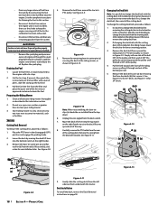
... garden hose to change the deck belt with the mowing deck still installed on page 18. Remove the bow-tie cotter pin (a) and flat washer (b) from around the tractor's PTO pulley. See Figure 4-11. It is possible to the lowest mowing position. 3. Remove the deck belt cover (a) by disconnecting the fuel line from the in the Lubrication section. 2. Deck Installation To install the deck, reverse the Deck Removal instructions on the riding mower. Replace the spark plug. Pull the fuel line free from the filter...
... garden hose to change the deck belt with the mowing deck still installed on page 18. Remove the bow-tie cotter pin (a) and flat washer (b) from around the tractor's PTO pulley. See Figure 4-11. It is possible to the lowest mowing position. 3. Remove the deck belt cover (a) by disconnecting the fuel line from the in the Lubrication section. 2. Deck Installation To install the deck, reverse the Deck Removal instructions on the riding mower. Replace the spark plug. Pull the fuel line free from the filter...
Operation Manual
Page 19
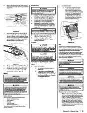
.... 2. Protect your tractor's discharged battery. 2. Remove the belt keeper (30" decks only) by using this manual. 6. See Figure 4-14. (a) Figure 4-14 7. When re-installing the battery, always connect the POSITIVE (Red) wire its warnings. CAUTION If the jumper battery is possible to change the blade with the deck still attached to positive post (+) of this feature will plug in the reverse order. 9. The charging unit will accompany the battery charging accessory. Blade WARNING Shut...
.... 2. Protect your tractor's discharged battery. 2. Remove the belt keeper (30" decks only) by using this manual. 6. See Figure 4-14. (a) Figure 4-14 7. When re-installing the battery, always connect the POSITIVE (Red) wire its warnings. CAUTION If the jumper battery is possible to change the blade with the deck still attached to positive post (+) of this feature will plug in the reverse order. 9. The charging unit will accompany the battery charging accessory. Blade WARNING Shut...

Operation Manual
Page 20
... details. PTO/Blade engaged. • Place blade engage lever in the operating position. See an authorized service dealer to have your drive belt replaced or phone Customer Support to between the deck opening . 2. Deck not properly leveled. • Perform side-to the spindle assembly. Engine speed too low. • Place throttle in FAST (rabbit) position. 2. Remove the hex flange nut that secures the blade to -side deck adjustment. 2. Deck chute or mulch plug not properly installed. • Check the installation of...
... details. PTO/Blade engaged. • Place blade engage lever in the operating position. See an authorized service dealer to have your drive belt replaced or phone Customer Support to between the deck opening . 2. Deck not properly leveled. • Perform side-to the spindle assembly. Engine speed too low. • Place throttle in FAST (rabbit) position. 2. Remove the hex flange nut that secures the blade to -side deck adjustment. 2. Deck chute or mulch plug not properly installed. • Check the installation of...


