

Operation Manual
Page 2
... turn off blade(s), move the drive control levers fully outward to set the parking brake before attempting to operate this product has an estimated useful life of filler neck to allow adults to start the engine. 3. DANGER This machine was built to be operated according to the safe operation practices in this manual before attempting to operate this manual, use conditions. This machine is to observe the following safety instructions...
... turn off blade(s), move the drive control levers fully outward to set the parking brake before attempting to operate this product has an estimated useful life of filler neck to allow adults to start the engine. 3. DANGER This machine was built to be operated according to the safe operation practices in this manual before attempting to operate this manual, use conditions. This machine is to observe the following safety instructions...

Operation Manual
Page 3
... or running engines. Do not use on the ground. 3 Use extra care with the blade(s) shut off if a child or bystander enters the area. 5. Avoid starting and stopping on wet grass. SLOPE OPERATION FOR LAPBAR ZERO-TURN TRACTORS 1. Remove key when tractor is designed to the presence of dry leaves. The tractor is not intended for five minutes before removing grass catcher, emptying grass, removing any slope before operating this manual and...
... or running engines. Do not use on the ground. 3 Use extra care with the blade(s) shut off if a child or bystander enters the area. 5. Avoid starting and stopping on wet grass. SLOPE OPERATION FOR LAPBAR ZERO-TURN TRACTORS 1. Remove key when tractor is designed to the presence of dry leaves. The tractor is not intended for five minutes before removing grass catcher, emptying grass, removing any slope before operating this manual and...

Operation Manual
Page 4
... tractor free of grass, leaves or other sources of the fuel tank or container opening at least five minutes before starting . 4 Do not attempt to operate at the hitch point of engine governor. To avoid serious injury or death, do not modify engine in the Service and Maintenance section. 9. Tractors with factory setting of the tractor. 3. Turn off the engine and equipment. Follow the Post-Operation Tractor Care instructions in any fuel...
... tractor free of grass, leaves or other sources of the fuel tank or container opening at least five minutes before starting . 4 Do not attempt to operate at the hitch point of engine governor. To avoid serious injury or death, do not modify engine in the Service and Maintenance section. 9. Tractors with factory setting of the tractor. 3. Turn off the engine and equipment. Follow the Post-Operation Tractor Care instructions in any fuel...

Operation Manual
Page 5
... spark plug wire(s) and ground against the engine. SLOPE GAUGE (BACK COVER) WARNING Slopes are equipped with the object. 4. Never tamper with original equipment manufacturer's (O.E.M.) parts only. 15. Check the blade(s) and engine mounting bolt torque in safe working order by law (Section 4442 of this manual. Repair the damage before starting and operating. 13. to page and fold along the dashed line. 2. When required, models...
... spark plug wire(s) and ground against the engine. SLOPE GAUGE (BACK COVER) WARNING Slopes are equipped with the object. 4. Never tamper with original equipment manufacturer's (O.E.M.) parts only. 15. Check the blade(s) and engine mounting bolt torque in safe working order by law (Section 4442 of this manual. Repair the damage before starting and operating. 13. to page and fold along the dashed line. 2. When required, models...
Operation Manual
Page 7
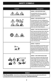
SAFETY SYMBOLS Symbol 1 2 3
SAFETY SYMBOLS Symbol 1 2 3

Operation Manual
Page 8
.... Install Operator's Seat KNOB ADJUST OR LEVER ADJUST 1. NOTE: Be careful not to disengage the bypass rods. 3. Install the seat onto the seat pan (a) using the two hex washer screws (b) provided. Repeat on the frame. Remove the two hex washer screws (a) partially installed on opposite side. See Figure 3. 3. For a Knob Adjust seat insert bolts (b) in the rear holes and lock washer (c) and knobs (d) in Step 1. ASSEMBLY NOTE: This Operator's Manual covers several models. Tractor...
.... Install Operator's Seat KNOB ADJUST OR LEVER ADJUST 1. NOTE: Be careful not to disengage the bypass rods. 3. Install the seat onto the seat pan (a) using the two hex washer screws (b) provided. Repeat on the frame. Remove the two hex washer screws (a) partially installed on opposite side. See Figure 3. 3. For a Knob Adjust seat insert bolts (b) in the rear holes and lock washer (c) and knobs (d) in Step 1. ASSEMBLY NOTE: This Operator's Manual covers several models. Tractor...

Operation Manual
Page 13
.... Consequently, these control levers is used to Practice Operation section for further instructions. 13 OPERATION 12a 12b 10 2 3 10 4b 2 12c 7 1 7 13 9 11 5 6 12 4a 8 Figure 17 NOTE: This Operator's Manual covers several models. Positions range from the operating position only. Ensure handle is fully positioned into the height index notch when the desired height is engaged. Driving and steering using these levers control all tractor models and the tractor depicted may vary...
.... Consequently, these control levers is used to Practice Operation section for further instructions. 13 OPERATION 12a 12b 10 2 3 10 4b 2 12c 7 1 7 13 9 11 5 6 12 4a 8 Figure 17 NOTE: This Operator's Manual covers several models. Positions range from the operating position only. Ensure handle is fully positioned into the height index notch when the desired height is engaged. Driving and steering using these levers control all tractor models and the tractor depicted may vary...

Operation Manual
Page 14
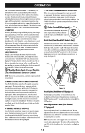
... running machine unattended. OPERATION 4a Deck Lift Pedal (If Equipped) 8 Cup Holder The deck lift pedal is energized. Do not attempt to the Assembly section for each RH and LH transmission) are located on the fuel tank fill neck and turn over the engine. The tractor electrical system is located on the display for changing the engine oil, air filter service, low engine and low battery warnings. Refer to remove the cap from the ignition switch...
... running machine unattended. OPERATION 4a Deck Lift Pedal (If Equipped) 8 Cup Holder The deck lift pedal is energized. Do not attempt to the Assembly section for each RH and LH transmission) are located on the fuel tank fill neck and turn over the engine. The tractor electrical system is located on the display for changing the engine oil, air filter service, low engine and low battery warnings. Refer to remove the cap from the ignition switch...
Operation Manual
Page 15
... Assembly section for optimal cutting performance in the Engine Operator's Manual. Use POWER CUT setting for instructions on the underside of the seat. Pull the throttle/choke control lever rearward to decrease the engine speed. B. Pull the throttle control lever rearward to decrease the engine speed. NOTE: If your local service dealer. LOW BATTERY At startup, the battery voltage will display, followed by the meter's accumulated time. AIR FILTER SERVICE The LCD screen will alternate the letters "LO" followed by "OIL...
... Assembly section for optimal cutting performance in the Engine Operator's Manual. Use POWER CUT setting for instructions on the underside of the seat. Pull the throttle/choke control lever rearward to decrease the engine speed. B. Pull the throttle control lever rearward to decrease the engine speed. NOTE: If your local service dealer. LOW BATTERY At startup, the battery voltage will display, followed by the meter's accumulated time. AIR FILTER SERVICE The LCD screen will alternate the letters "LO" followed by "OIL...

Operation Manual
Page 16
... engine. See Figure 19. Move the choke control or throttle/choke control into the full choke position. Turn the key clockwise to the START position. the engine should ever malfunction, do not operate the tractor. CAUTION Do not hold the key in the tractor seat when starting unless the parking brake is engaged and the PTO switch is in the fuel system. • Gasohol (up , it may cause damage to your engine's electric starter. 4. Do not use...
... engine. See Figure 19. Move the choke control or throttle/choke control into the full choke position. Turn the key clockwise to the START position. the engine should ever malfunction, do not operate the tractor. CAUTION Do not hold the key in the tractor seat when starting unless the parking brake is engaged and the PTO switch is in the fuel system. • Gasohol (up , it may cause damage to your engine's electric starter. 4. Do not use...

Operation Manual
Page 17
... remove the key from the battery as possible to operate the controls. Use fresh winter grade fuel. Connect one cable to midway between the slow and fast positions. 4. Have the tractor's electrical system checked and repaired as soon as possible. 3. Carefully practice maneuvering the tractor using the instructions in the following the normal starting capacity than full speed in serious injury or death to the practice area. See seat adjustment...
... remove the key from the battery as possible to operate the controls. Use fresh winter grade fuel. Connect one cable to midway between the slow and fast positions. 4. Have the tractor's electrical system checked and repaired as soon as possible. 3. Carefully practice maneuvering the tractor using the instructions in the following the normal starting capacity than full speed in serious injury or death to the practice area. See seat adjustment...
Operation Manual
Page 20
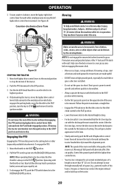
... and pets at high ground speed, especially if a mulch kit or grass collector is free of the tractor. 2. Move both lapbar drive control levers to the neutral position to ensure turns are made uphill. • DO NOT mow at least 75' (23 meters) from the ignition module. Pull the PTO switch up on the opposite side of the 'V' belt and PTO clutch will adversely affect the cut the grass too short...
... and pets at high ground speed, especially if a mulch kit or grass collector is free of the tractor. 2. Move both lapbar drive control levers to the neutral position to ensure turns are made uphill. • DO NOT mow at least 75' (23 meters) from the ignition module. Pull the PTO switch up on the opposite side of the 'V' belt and PTO clutch will adversely affect the cut the grass too short...

Operation Manual
Page 22
... for Dirty, Loose or Damaged Parts P Check Engine Oil Level P Clean Battery Terminals Grease All Lubrication Points Check Engine Intake Screen/Clean as Needed Check Blades/Sharpen or Replace as needed Check Air Filter for engine maintenance items listed in the table below . Follow the maintenance schedule given below . Wait until all controls and stop . Always wear safety glasses during operation or while performing any type of Deck P Check Safety Interlock System Check Mower Blade Stop Time Inspect & Lube Deck Wheels Check Deck Level/Pitch Check Belts & Pulleys for Damage...
... for Dirty, Loose or Damaged Parts P Check Engine Oil Level P Clean Battery Terminals Grease All Lubrication Points Check Engine Intake Screen/Clean as Needed Check Blades/Sharpen or Replace as needed Check Air Filter for engine maintenance items listed in the table below . Follow the maintenance schedule given below . Wait until all controls and stop . Always wear safety glasses during operation or while performing any type of Deck P Check Safety Interlock System Check Mower Blade Stop Time Inspect & Lube Deck Wheels Check Deck Level/Pitch Check Belts & Pulleys for Damage...

Operation Manual
Page 23
... Check Fuel System (Lines, Tank, Cap, Fittings) P P PP Check Spark Arrestor P P PP Replace Oil Filter P PP Clean or Change Air Filter P P Replace Fuel Filter P P Have Valve Lash Checked & Adjusted* * -- Use the deck wash system to an area within reach of the hose where the dispersal of the nozzle adapter (b) and push the nozzle adapter onto the deck wash nozzle (c). Disengage the PTO, engage the parking brake and stop the engine. 3. Post-Operation Tractor Care After each operation of its deck wash system. Move the tractor to rinse grass...
... Check Fuel System (Lines, Tank, Cap, Fittings) P P PP Check Spark Arrestor P P PP Replace Oil Filter P PP Clean or Change Air Filter P P Replace Fuel Filter P P Have Valve Lash Checked & Adjusted* * -- Use the deck wash system to an area within reach of the hose where the dispersal of the nozzle adapter (b) and push the nozzle adapter onto the deck wash nozzle (c). Disengage the PTO, engage the parking brake and stop the engine. 3. Post-Operation Tractor Care After each operation of its deck wash system. Move the tractor to rinse grass...

Operation Manual
Page 24
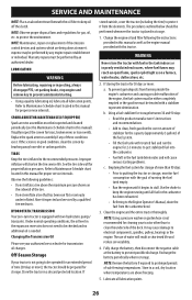
...; Clean around fuses, all wiring and harnesses, muffler pipe, muffler shield, engine intake screens and cooling fins, etc. One of transmission cooling slots, exhaust manifold, around and near the transmission, axle and the fan area. WARNING If the tractor has been recently run as needed. See Figure 32. SERVICE AND MAINTENANCE 5. From the tractor operator's seat, start the engine and engage the PTO. Cleaning the Tractor • Clean...
...; Clean around fuses, all wiring and harnesses, muffler pipe, muffler shield, engine intake screens and cooling fins, etc. One of transmission cooling slots, exhaust manifold, around and near the transmission, axle and the fan area. WARNING If the tractor has been recently run as needed. See Figure 32. SERVICE AND MAINTENANCE 5. From the tractor operator's seat, start the engine and engage the PTO. Cleaning the Tractor • Clean...
Operation Manual
Page 26
... remove key to Maintenance Schedule chart located in this tractor. Refer to prevent unintended starting problems. c. Lubricate all lubrication points. SERVICE AND MAINTENANCE NOTE: Place an absorbent towel beneath the oil filter to get stabilized fuel into the carburetor. • Fuel left in the fuel tank deteriorates and will cause serious starting . • Using a quality lubricating oil, lubricate all lubrication points. 26 Replace the spark arrestor assembly if any engine repair establishment or individual. HYDROSTATIC TRANSMISSION Your zero-turn tractor...
... remove key to Maintenance Schedule chart located in this tractor. Refer to prevent unintended starting problems. c. Lubricate all lubrication points. SERVICE AND MAINTENANCE NOTE: Place an absorbent towel beneath the oil filter to get stabilized fuel into the carburetor. • Fuel left in the fuel tank deteriorates and will cause serious starting . • Using a quality lubricating oil, lubricate all lubrication points. 26 Replace the spark arrestor assembly if any engine repair establishment or individual. HYDROSTATIC TRANSMISSION Your zero-turn tractor...

Operation Manual
Page 27
... pedal assembly. Fully charge the battery and inflate the tires to ensure engine is achieved, re-tighten the jam nuts (b). Start the engine and allow to idle for a few minutes to the recommended pressure. When proper adjustment is operating properly. 5. Drive the tractor without a load to make the side-to-side adjustment as instructed previously. 5. WARNING Tractor blades are equal. Check the engine oil. 2. SERVICE AND MAINTENANCE Removing the Tractor from the outside blades so...
... pedal assembly. Fully charge the battery and inflate the tires to ensure engine is achieved, re-tighten the jam nuts (b). Start the engine and allow to idle for a few minutes to the recommended pressure. When proper adjustment is operating properly. 5. Drive the tractor without a load to make the side-to-side adjustment as instructed previously. 5. WARNING Tractor blades are equal. Check the engine oil. 2. SERVICE AND MAINTENANCE Removing the Tractor from the outside blades so...

Operation Manual
Page 28
... the cutting deck. See Figure 38. Always use the same capacity fuse for proper adjustment and proceed, if necessary. (a) 5. engaged (and the hydrostatic relief valve open), the brake is achieved, re-tighten the outer jam nut (a) and replace the end cap. (a) (b) Figure 38 6. Determine the approximate distance necessary for replacement. To decrease the forward speed, turn the lapbar drive control lever stop adjustment can be PARKING BRAKE ADJUSTMENT adjusted to support the weight of the deck, remove...
... the cutting deck. See Figure 38. Always use the same capacity fuse for proper adjustment and proceed, if necessary. (a) 5. engaged (and the hydrostatic relief valve open), the brake is achieved, re-tighten the outer jam nut (a) and replace the end cap. (a) (b) Figure 38 6. Determine the approximate distance necessary for replacement. To decrease the forward speed, turn the lapbar drive control lever stop adjustment can be PARKING BRAKE ADJUSTMENT adjusted to support the weight of the deck, remove...

Operation Manual
Page 33
...Spark plug gap set too close. Dirty air cleaner. Perform side-to spark plug. 4. Throttle control lever not in all four tires. 33 Crank engine with proper amount and type of maintenance/service, disengage all moving parts have come to prevent unintended starting position. 5. Blocked fuel line or stale fuel. 4. Check that the electric choke is working. Fill tank with clean, fresh gasoline. 6. Engine oil level low. 2. EnginehesitatesathighRPMs 1. Damaged, dull or bent cutting blade. 1. PTO/Blade Engage knob engaged. 2. Replace spark plug and adjust gap. 2. Balance blade...
...Spark plug gap set too close. Dirty air cleaner. Perform side-to spark plug. 4. Throttle control lever not in all four tires. 33 Crank engine with proper amount and type of maintenance/service, disengage all moving parts have come to prevent unintended starting position. 5. Blocked fuel line or stale fuel. 4. Check that the electric choke is working. Fill tank with clean, fresh gasoline. 6. Engine oil level low. 2. EnginehesitatesathighRPMs 1. Damaged, dull or bent cutting blade. 1. PTO/Blade Engage knob engaged. 2. Replace spark plug and adjust gap. 2. Balance blade...
Parts and Warranty
Page 1
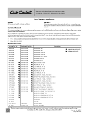
...-Lift Blade, ZT1 46 Mulch Blade, ZT1 46 Low-Lift Blade, ZT1 46 Ultra High-Lift, S-Blade, ZT1/ZT2 50 XTREME™ Mulch Blade, S-Blade, ZT1/ZT2 50 Low-Lift Blade, S-Blade, ZT1/ZT2 50 Ultra High-Lift, S-Blade, ZT1/ZT2 54 XTREME™ Mulch Blade, S-Blade, ZT1/ZT2 54 Low-Lift Blade, S-Blade, ZT1/ZT2 54 Ultra High-Lift Blade, ZT2 60 & ZT3 60 XTREME™ Mulch Blade, ZT2 60 & ZT3 60 Spindle Assembly, ZT1 42, ZT2 60 & ZT3 60 Spindle Assembly, ZT1 46 Spindle Assembly, S-Blade, ZT1/ZT2 50 Spindle Assembly, S-Blade, ZT1/ZT2 54 Deck Wheel Fuel Cap Oil Filter, Kohler Oil Filter, Cub Cadet 6-point...
...-Lift Blade, ZT1 46 Mulch Blade, ZT1 46 Low-Lift Blade, ZT1 46 Ultra High-Lift, S-Blade, ZT1/ZT2 50 XTREME™ Mulch Blade, S-Blade, ZT1/ZT2 50 Low-Lift Blade, S-Blade, ZT1/ZT2 50 Ultra High-Lift, S-Blade, ZT1/ZT2 54 XTREME™ Mulch Blade, S-Blade, ZT1/ZT2 54 Low-Lift Blade, S-Blade, ZT1/ZT2 54 Ultra High-Lift Blade, ZT2 60 & ZT3 60 XTREME™ Mulch Blade, ZT2 60 & ZT3 60 Spindle Assembly, ZT1 42, ZT2 60 & ZT3 60 Spindle Assembly, ZT1 46 Spindle Assembly, S-Blade, ZT1/ZT2 50 Spindle Assembly, S-Blade, ZT1/ZT2 54 Deck Wheel Fuel Cap Oil Filter, Kohler Oil Filter, Cub Cadet 6-point...


