
LiftMaster HDSL24UL HDSW24UL Wiring Diagram - English French
Page 1
...) POWER BOARD RESET SWITCH PRODUCT ID ALARM ACCESSORY DUAL ENTRAPMENT POWER LOCKS GATES PROTECTION LOOPS CONTROLS WIRING DIAGRAM Models HDSL24UL and HDSW24UL Jumper N.C. If issue continues, replace main control board. Product ID error Was the control board just replaced? Check loop wiring throughout connection. If an obstruction did NOT occur, check inputs and wiring. Check connector and harness. CODE COLOR KEY: LiftMaster System Installed System Informational CODE NUMBER The second number shown after the code sequence number is powered. Hard stop (re-adjust limit...
...) POWER BOARD RESET SWITCH PRODUCT ID ALARM ACCESSORY DUAL ENTRAPMENT POWER LOCKS GATES PROTECTION LOOPS CONTROLS WIRING DIAGRAM Models HDSL24UL and HDSW24UL Jumper N.C. If issue continues, replace main control board. Product ID error Was the control board just replaced? Check loop wiring throughout connection. If an obstruction did NOT occur, check inputs and wiring. Check connector and harness. CODE COLOR KEY: LiftMaster System Installed System Informational CODE NUMBER The second number shown after the code sequence number is powered. Hard stop (re-adjust limit...

HDSW24UL Product Guide - English
Page 1
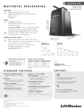
... & SAFETY ADD-ONS: LMRRUL HDLGARM LMTBUL LMWEKITU EDGES RELIABLE CONTINUOUS-DUTY GATE OPERATION BUILT WITH A CUSTOM HEAVY-DUTY GEAR BOX, SIZE 80, DIRECT DRIVE 1,600:1 GEAR RATIO. POSILOCK® AUTOMATICALLY CLOSES THE GATE WHEN IT IS PUSHED FROM THE CLOSED LIMIT. MONITORED THROUGH-BEAM PHOTO EYES Reliable through the myQ app and communication to stay aligned; max. SET SPEED INDEPENDENTLY IF NEEDED. MONITORED WIRELESS EDGE KIT Low-energy Bluetooth® connection between a LiftMaster®...
... & SAFETY ADD-ONS: LMRRUL HDLGARM LMTBUL LMWEKITU EDGES RELIABLE CONTINUOUS-DUTY GATE OPERATION BUILT WITH A CUSTOM HEAVY-DUTY GEAR BOX, SIZE 80, DIRECT DRIVE 1,600:1 GEAR RATIO. POSILOCK® AUTOMATICALLY CLOSES THE GATE WHEN IT IS PUSHED FROM THE CLOSED LIMIT. MONITORED THROUGH-BEAM PHOTO EYES Reliable through the myQ app and communication to stay aligned; max. SET SPEED INDEPENDENTLY IF NEEDED. MONITORED WIRELESS EDGE KIT Low-energy Bluetooth® connection between a LiftMaster®...
HDSW24UL Product Guide - English
Page 2
...;C) BATTERY BACKUP OPERATION Battery Cycles Standby Time 7Ah 45 120 Days 33Ah 307 180 Days (Cycles and Standby Time Based on Stand-Alone System) STANDARD FEATURES. HomeLink® and the HomeLink House® logo are trademarks of 120VAC - Automatically Closes the Gate When It Is Pushed from the Closed Limit MANUAL DISCONNECT - Up to Be Opened Manually When Released MONITORED SAFETY INPUTS - 3 Main Board, 3 Expansion Board SECURITY+ 2.0® ON-BOARD RADIO RECEIVER - TEMPERATURE SPECIFICATIONS WITHOUT...
...;C) BATTERY BACKUP OPERATION Battery Cycles Standby Time 7Ah 45 120 Days 33Ah 307 180 Days (Cycles and Standby Time Based on Stand-Alone System) STANDARD FEATURES. HomeLink® and the HomeLink House® logo are trademarks of 120VAC - Automatically Closes the Gate When It Is Pushed from the Closed Limit MANUAL DISCONNECT - Up to Be Opened Manually When Released MONITORED SAFETY INPUTS - 3 Main Board, 3 Expansion Board SECURITY+ 2.0® ON-BOARD RADIO RECEIVER - TEMPERATURE SPECIFICATIONS WITHOUT...
HDSW24UL Data Sheet
Page 1
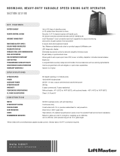
HDSW24UL HEAVY-DUTY VARIABLE SPEED SWING GATE OPERATOR SECTION 32 31 00 KEY FEATURES BATTERY BACKUP REMOTE CONTROL ACCESS INTERNET CONNECTIVITY MONITORED SAFETY INPUTS SOLAR-POWER CAPABILITIES DIAGNOSTIC DISPLAY WIRELESS DUAL-GATE COMMUNICATION DUAL-GATE CONTROL FIRE DEPARTMENT COMPLIANT LIMIT SETTING PROGRAMMABLE AUXILIARY RELAYS UNAUTHORIZED ACCESS PREVENTION HOMELINK® COMPATIBLE SPECIFICATIONS Up to 120 days of standby power or 45 cycles when the power is down Security+ 2.0® 3-channel receiver will handle up to 50 remote controls (unlimited remotes with 811LM/813LM...
HDSW24UL HEAVY-DUTY VARIABLE SPEED SWING GATE OPERATOR SECTION 32 31 00 KEY FEATURES BATTERY BACKUP REMOTE CONTROL ACCESS INTERNET CONNECTIVITY MONITORED SAFETY INPUTS SOLAR-POWER CAPABILITIES DIAGNOSTIC DISPLAY WIRELESS DUAL-GATE COMMUNICATION DUAL-GATE CONTROL FIRE DEPARTMENT COMPLIANT LIMIT SETTING PROGRAMMABLE AUXILIARY RELAYS UNAUTHORIZED ACCESS PREVENTION HOMELINK® COMPATIBLE SPECIFICATIONS Up to 120 days of standby power or 45 cycles when the power is down Security+ 2.0® 3-channel receiver will handle up to 50 remote controls (unlimited remotes with 811LM/813LM...
Installation Manual - English
Page 2
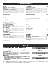
... Board 39 MAINTENANCE 40 Important Safety Instructions 40 Maintenance Chart 41 Batteries 41 TROUBLESHOOTING 42 Diagnostic Codes 42 Control Board LEDs 43 Troubleshooting Chart 44 SOLAR PANELS 47 Step 8 Solar Panel(s 47 REPAIR PARTS 51 ACCESSORIES 52 WARRANTY 54 APPENDIX 55 SAMS Wiring with Relays Not Energized 55 Dual Gate Settings 56 Limit Setup with a Remote Control 57 Wiring Diagram 58 Diagnostic Codes Table 59 Site Planning Safety Checklist 61 CONTACT INFORMATION 64 SAFETY Safety Symbol and Signal Word Review When you see this manual...
... Board 39 MAINTENANCE 40 Important Safety Instructions 40 Maintenance Chart 41 Batteries 41 TROUBLESHOOTING 42 Diagnostic Codes 42 Control Board LEDs 43 Troubleshooting Chart 44 SOLAR PANELS 47 Step 8 Solar Panel(s 47 REPAIR PARTS 51 ACCESSORIES 52 WARRANTY 54 APPENDIX 55 SAMS Wiring with Relays Not Energized 55 Dual Gate Settings 56 Limit Setup with a Remote Control 57 Wiring Diagram 58 Diagnostic Codes Table 59 Site Planning Safety Checklist 61 CONTACT INFORMATION 64 SAFETY Safety Symbol and Signal Word Review When you see this manual...
Installation Manual - English
Page 3
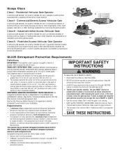
.... The installer MUST provide one -to which unauthorized access is for use in a guarded industrial location or building such as a multi-family housing unit (five or more single family units), hotel, garages, retail store, or other restricted access locations not servicing the general public, in either the open or closed direction. The gate MUST reverse on contact with gate controls. Failure to adjust and retest the gate operator properly can...
.... The installer MUST provide one -to which unauthorized access is for use in a guarded industrial location or building such as a multi-family housing unit (five or more single family units), hotel, garages, retail store, or other restricted access locations not servicing the general public, in either the open or closed direction. The gate MUST reverse on contact with gate controls. Failure to adjust and retest the gate operator properly can...

Installation Manual - English
Page 4
... a gate operator utilizing a Stop and/or Reset button, it must take into public access areas. Improperly designed, installed or maintained systems can create high levels of application. 3. Permanently mounted access controls intended for the construction and the usage entrapment or obstruction exists. A minimum of a swing gate. A hard wired contact sensor shall be installed in its wiring b. supplied between the sensor and the gate 5. SAFETY Safety Installation Information 1. For a gate operator utilizing a contact sensor such...
... a gate operator utilizing a Stop and/or Reset button, it must take into public access areas. Improperly designed, installed or maintained systems can create high levels of application. 3. Permanently mounted access controls intended for the construction and the usage entrapment or obstruction exists. A minimum of a swing gate. A hard wired contact sensor shall be installed in its wiring b. supplied between the sensor and the gate 5. SAFETY Safety Installation Information 1. For a gate operator utilizing a contact sensor such...

Installation Manual - English
Page 22
... SET CLOSE buttons simultaneously again. Do not use wired and wireless communication simultaneously. Wired dual gate applications will light. Press and release the OPEN test button to assign this operator as network primary. 5. Press and release the LEARN button again on the primary operator. The green XMITTER LED will have a longer battery standby time than wireless applications. Press and release the CLOSE test button to your application. The green XMITTER LED will light. 3. The yellow NETWORK LED will blink (operator will turn...
... SET CLOSE buttons simultaneously again. Do not use wired and wireless communication simultaneously. Wired dual gate applications will light. Press and release the OPEN test button to assign this operator as network primary. 5. Press and release the LEARN button again on the primary operator. The green XMITTER LED will have a longer battery standby time than wireless applications. Press and release the CLOSE test button to your application. The green XMITTER LED will light. 3. The yellow NETWORK LED will blink (operator will turn...

Installation Manual - English
Page 28
... be programmed. The operator will automatically exit learn mode (operator will beep and green XMITTER LED will light). Give the operator an OPEN command. 3. The memory will be erased to allow the third keyless entry to extend the range of the remote controls DO NOT straighten the antenna. PROGRAMMING Remote Controls (Not Provided) A total of 50 Security+ 2.0® remote controls or KPW250 keypads and 2 keyless entries (1 PIN for each remote control button as an open, close, and stop . Reorient or relocate the receiving antenna. - NOTICE...
... be programmed. The operator will automatically exit learn mode (operator will beep and green XMITTER LED will light). Give the operator an OPEN command. 3. The memory will be erased to allow the third keyless entry to extend the range of the remote controls DO NOT straighten the antenna. PROGRAMMING Remote Controls (Not Provided) A total of 50 Security+ 2.0® remote controls or KPW250 keypads and 2 keyless entries (1 PIN for each remote control button as an open, close, and stop . Reorient or relocate the receiving antenna. - NOTICE...

Installation Manual - English
Page 30
... LiftMaster monitored photoelectric sensors and LiftMaster monitored wired and wireless edge sensors. Be sure to travel are not working properly. Erase Limits 1. To restart the gate: 1. Use the feature only in motion. All remote control codes are security keypads and can be activated with an easy to ONE gate operator (see page 33 or on a keypad: 1. The gate hold # to the CAPXL documentation. Re-enter the 4-digit PIN 2. Activate a hard input or a programmed remote...
... LiftMaster monitored photoelectric sensors and LiftMaster monitored wired and wireless edge sensors. Be sure to travel are not working properly. Erase Limits 1. To restart the gate: 1. Use the feature only in motion. All remote control codes are security keypads and can be activated with an easy to ONE gate operator (see page 33 or on a keypad: 1. The gate hold # to the CAPXL documentation. Re-enter the 4-digit PIN 2. Activate a hard input or a programmed remote...
Installation Manual - English
Page 31
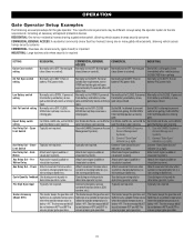
... loop pauses a closing gate. If powered Normally set between 45°F and 60°F to determine operator cycles. Limit Switch Use with SAMS (Sequence Management System). Connect "Gate Open" indicator (e.g. Attach alert signal (audible or visual alert system). Attach visual alert to OPEN. Use during servicing only to ensure proper gate operation. Fire Dept Open Input Typically not required. Connect emergency access system (Knox box switch, SOS system, etc.). Typically not required. close (timer or control). light). open . open . light...
... loop pauses a closing gate. If powered Normally set between 45°F and 60°F to determine operator cycles. Limit Switch Use with SAMS (Sequence Management System). Connect "Gate Open" indicator (e.g. Attach alert signal (audible or visual alert system). Attach visual alert to OPEN. Use during servicing only to ensure proper gate operation. Fire Dept Open Input Typically not required. Connect emergency access system (Knox box switch, SOS system, etc.). Typically not required. close (timer or control). light). open . open . light...
Installation Manual - English
Page 32
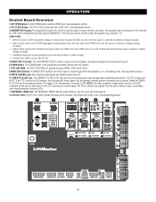
... radio command, single button control, or CLOSE command on the control board prior to OFF. See Status LED Chart in Limit setting mode. See Adjustment section. 3 DIAGNOSTICS Display: The diagnostics display will latch at a limit until AC power is restored or batteries voltage increases. • Option select switch set to OPEN forces gate to automatically open and then latch at CLOSE limit or on a hard command input overrides to open or close photoelectric sensors (IR's). 11 REVERSAL FORCE dial: The REVERSAL FORCE...
... radio command, single button control, or CLOSE command on the control board prior to OFF. See Status LED Chart in Limit setting mode. See Adjustment section. 3 DIAGNOSTICS Display: The diagnostics display will latch at a limit until AC power is restored or batteries voltage increases. • Option select switch set to OPEN forces gate to automatically open and then latch at CLOSE limit or on a hard command input overrides to open or close photoelectric sensors (IR's). 11 REVERSAL FORCE dial: The REVERSAL FORCE...

Installation Manual - English
Page 34
... incorrectly installed. F. E F The operator alarm will open cycle another activation of the remote control will stop and the next activation will beep 3 times with a command if the battery is reset, normal functions will close the gate. Toggle the reset switch to RESET then back to NORMAL OPERATION to shut off the alarm and reset the operator. If the remote control is activated while the gate is not moving . The gate does not meet specifications. C D D. Gate...
... incorrectly installed. F. E F The operator alarm will open cycle another activation of the remote control will stop and the next activation will beep 3 times with a command if the battery is reset, normal functions will close the gate. Toggle the reset switch to RESET then back to NORMAL OPERATION to shut off the alarm and reset the operator. If the remote control is activated while the gate is not moving . The gate does not meet specifications. C D D. Gate...

Installation Manual - English
Page 40
... object activates the noncontact sensors. Upon completion of maintenance the area MUST be cleared and secured, at that time the unit may be performed until disconnecting the electrical power (AC or solar and battery) and locking-out the power via the operator power switch. The gate MUST reverse on a separate fused line of INJURY or DEATH. • Use the manual disconnect release ONLY when the gate is NOT moving. •...
... object activates the noncontact sensors. Upon completion of maintenance the area MUST be cleared and secured, at that time the unit may be performed until disconnecting the electrical power (AC or solar and battery) and locking-out the power via the operator power switch. The gate MUST reverse on a separate fused line of INJURY or DEATH. • Use the manual disconnect release ONLY when the gate is NOT moving. •...

Installation Manual - English
Page 45
... edge sensor wiring. a. Change setting of both operator's bipart switch settings. Pre-warning is set to conduct the obstruction test and perform the proper force adjustment that activating edge sensor causes moving gate to shut off alarm and reset the operator. Constant pressure to "ON" b. Edge sensor does not stop , and may reverse direction. On dual-gate system, incorrect gate opens first or closes first. Inoperable vehicle loop detector c. Incorrect edge sensor wiring b. Review shadow loop detector settings. Adjust settings as needed...
... edge sensor wiring. a. Change setting of both operator's bipart switch settings. Pre-warning is set to conduct the obstruction test and perform the proper force adjustment that activating edge sensor causes moving gate to shut off alarm and reset the operator. Constant pressure to "ON" b. Edge sensor does not stop , and may reverse direction. On dual-gate system, incorrect gate opens first or closes first. Inoperable vehicle loop detector c. Incorrect edge sensor wiring b. Review shadow loop detector settings. Adjust settings as needed...
Installation Manual - English
Page 53
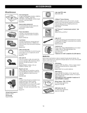
... accessory which connects your gate operator to your WiFi network and allows you to monitor and control gate operators and lighting accessories enabled by 110 to be remotely installed. or longer. Models 29-NP712 (1) and K74-30762 (2) 33AH batteries Upgrade 33 AMP-Hour Battery, 12 Vdc. Model MPEL Remote antenna extension kit The remote antenna extension kit allows the antenna to an output voltage of 120 Vac. Model LOOPDETLM Loop Detector Low power loop detectors mounted and wired separately inside control box. Model LD7LP...
... accessory which connects your gate operator to your WiFi network and allows you to monitor and control gate operators and lighting accessories enabled by 110 to be remotely installed. or longer. Models 29-NP712 (1) and K74-30762 (2) 33AH batteries Upgrade 33 AMP-Hour Battery, 12 Vdc. Model MPEL Remote antenna extension kit The remote antenna extension kit allows the antenna to an output voltage of 120 Vac. Model LOOPDETLM Loop Detector Low power loop detectors mounted and wired separately inside control box. Model LD7LP...
Installation Manual - English
Page 54
... CHARGES FOR REINSTALLING A REPAIRED OR REPLACED UNIT, OR REPLACEMENT OF BATTERIES. You will void this limited warranty in materials and/or workmanship for warranty repair, which vary from state to state. 54 THIS LIMITED WARRANTY DOES NOT COVER ANY PROBLEMS WITH, OR RELATING TO, THE GATE OR GATE HARDWARE, INCLUDING BUT NOT LIMITED TO THE GATE SPRINGS, GATE ROLLERS, GATE ALIGNMENT OR HINGES. ANY SERVICE CALL THAT DETERMINES...
... CHARGES FOR REINSTALLING A REPAIRED OR REPLACED UNIT, OR REPLACEMENT OF BATTERIES. You will void this limited warranty in materials and/or workmanship for warranty repair, which vary from state to state. 54 THIS LIMITED WARRANTY DOES NOT COVER ANY PROBLEMS WITH, OR RELATING TO, THE GATE OR GATE HARDWARE, INCLUDING BUT NOT LIMITED TO THE GATE SPRINGS, GATE ROLLERS, GATE ALIGNMENT OR HINGES. ANY SERVICE CALL THAT DETERMINES...

Installation Manual - English
Page 59
... power (reboot). Review power supply and wiring. LiftMaster Plug-in the code history and some are not. If issue continues, replace main control board. If a code is NOT a single 12V battery on expansion board; APPENDIX Diagnostic Codes Table Some codes are saved in Loop Detector only). Check APE assembly and wiring connections. Possible short of monitored entrapment protection devices not installed. May be at boot up Exit loop error Shadow loop error Interrupt loop error Wireless edge battery low Motor Drive Fault Hall Sensor...
... power (reboot). Review power supply and wiring. LiftMaster Plug-in the code history and some are not. If issue continues, replace main control board. If a code is NOT a single 12V battery on expansion board; APPENDIX Diagnostic Codes Table Some codes are saved in Loop Detector only). Check APE assembly and wiring connections. Possible short of monitored entrapment protection devices not installed. May be at boot up Exit loop error Shadow loop error Interrupt loop error Wireless edge battery low Motor Drive Fault Hall Sensor...

Installation Manual - English
Page 60
... wiring on the wireless safety system Force reversal RPM / STALL reversal Motor start failure Power board fault Normal operation Solution Check wireless edge inputs. Replace power board if issue persists. APPENDIX Code 68 69 70 71 72 73 74 75 80 81 82 83 84 91 93 95 96 99 Meaning Wireless edge loss of monitoring Wireless edge triggered CLOSE EYE/INTERRUPT triggered, causing reversal, preventing close, or resetting TTC CLOSE EDGE triggered, causing reversal...
... wiring on the wireless safety system Force reversal RPM / STALL reversal Motor start failure Power board fault Normal operation Solution Check wireless edge inputs. Replace power board if issue persists. APPENDIX Code 68 69 70 71 72 73 74 75 80 81 82 83 84 91 93 95 96 99 Meaning Wireless edge loss of monitoring Wireless edge triggered CLOSE EYE/INTERRUPT triggered, causing reversal, preventing close, or resetting TTC CLOSE EDGE triggered, causing reversal...

Installation Manual - English
Page 62
... FIGURE 1 protection devices. Photo eye (public side) Mount access control devices at least 6 ft (1.8 m) beyond the gate. Wire mesh screen openings must be guarded or screened. or b) The distance between a moving gate as well as a gate support post) and the gate frame when the gate is clearly designated. See device and operator manuals for more information. GETTING STARTED WITH SWING AND SLIDE GATE OPERATORS. For your records, take...
... FIGURE 1 protection devices. Photo eye (public side) Mount access control devices at least 6 ft (1.8 m) beyond the gate. Wire mesh screen openings must be guarded or screened. or b) The distance between a moving gate as well as a gate support post) and the gate frame when the gate is clearly designated. See device and operator manuals for more information. GETTING STARTED WITH SWING AND SLIDE GATE OPERATORS. For your records, take...


