
Owners Manual
Page 78
... devices Position on the vehicle 26 Fuel tank plug 27 Seat catch and helmet hooks 28 Side stand 29 Rear shock absorber adjusters 30 Directions for use 32 Running-in recommendations 32 Pre-ride checks 33 Starting the engine 34 Moving off 36 Braking 37 Stopping the motorcycle 38 Refuelling 38 Parking 39 Tool kit and accessories 40 26 E General 6 Warranty 6 Symbols 6 Useful information for...
... devices Position on the vehicle 26 Fuel tank plug 27 Seat catch and helmet hooks 28 Side stand 29 Rear shock absorber adjusters 30 Directions for use 32 Running-in recommendations 32 Pre-ride checks 33 Starting the engine 34 Moving off 36 Braking 37 Stopping the motorcycle 38 Refuelling 38 Parking 39 Tool kit and accessories 40 26 E General 6 Warranty 6 Symbols 6 Useful information for...
Owners Manual
Page 79
Main maintenance operations 41 Lifting the fuel tank 41 Changing the air filter 42 Checking brake and clutch fluid level 43 Checking brake pads for wear 44 Lubricating cables and joints 45 Throttle cable adjustment 46 Charging the battery 47 Chain tensioning 48 Chain lubrication 49 Replacing bulbs 50 Beam setting 53 Tyres 54 Checking engine oil level 56 Cleaning and replacing the spark plugs 57 Cleaning the motorcycle 58 Storing the bike away 59...
Main maintenance operations 41 Lifting the fuel tank 41 Changing the air filter 42 Checking brake and clutch fluid level 43 Checking brake pads for wear 44 Lubricating cables and joints 45 Throttle cable adjustment 46 Charging the battery 47 Chain tensioning 48 Chain lubrication 49 Replacing bulbs 50 Beam setting 53 Tyres 54 Checking engine oil level 56 Cleaning and replacing the spark plugs 57 Cleaning the motorcycle 58 Storing the bike away 59...

Owners Manual
Page 81
... handlebar firmly with you when riding; Never start or run the engine indoors. Ride within a short time. Be sure you will be spilled on slip roads to be hot, even after engine is switched off the engine when refuelling. Always turn indicators. Always make sure you have your speed to the visibility, road and traffic conditions you need a valid licence to access...
... handlebar firmly with you when riding; Never start or run the engine indoors. Ride within a short time. Be sure you will be spilled on slip roads to be hot, even after engine is switched off the engine when refuelling. Always turn indicators. Always make sure you have your speed to the visibility, road and traffic conditions you need a valid licence to access...

Owners Manual
Page 88
... engine operation whenever the ignition switch is turned off and re-program other keys. The key A performs the same functions as a password and tells the CPU that reports their identification number. Warning Keep the keys in a safe place. This signal is generated by a special antenna incorporated in the handgrip of the fuel tank filler plug - Keys (fig. 7) The Owner receives a set of keys comprising: - 1 RED key (A) - 2 BLACK keys (B) Warning Red key...
... engine operation whenever the ignition switch is turned off and re-program other keys. The key A performs the same functions as a password and tells the CPU that reports their identification number. Warning Keep the keys in a safe place. This signal is generated by a special antenna incorporated in the handgrip of the fuel tank filler plug - Keys (fig. 7) The Owner receives a set of keys comprising: - 1 RED key (A) - 2 BLACK keys (B) Warning Red key...

Owners Manual
Page 89
... following procedure gives the chance to disable "engine block" function -immediately signalled by the orange EOBD warning light (7, fig. 4). In case of engine disabled and therefore if engine will not start up after the key-ON. E fig. 8 A fig. 9 15 Code card A CODE CARD (fig. 8) is supplied together with the keys, it indicates the electronic code (A, fig. 9) to be carried out only if...
... following procedure gives the chance to disable "engine block" function -immediately signalled by the orange EOBD warning light (7, fig. 4). In case of engine disabled and therefore if engine will not start up after the key-ON. E fig. 8 A fig. 9 15 Code card A CODE CARD (fig. 8) is supplied together with the keys, it indicates the electronic code (A, fig. 9) to be carried out only if...

Owners Manual
Page 103
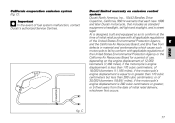
... its rear wheel facing downhill. Warning Do not sit on asphalt softened by the heat or the motorcycle may fall over. Note Check for proper operation of the stand mechanism (two springs, one into the other) and the safety sensor (2) at the same time, lift the thrust arm (1) with a gear engaged, pull the clutch lever (in neutral. Do not park on soft or pebbled ground...
... its rear wheel facing downhill. Warning Do not sit on asphalt softened by the heat or the motorcycle may fall over. Note Check for proper operation of the stand mechanism (two springs, one into the other) and the safety sensor (2) at the same time, lift the thrust arm (1) with a gear engaged, pull the clutch lever (in neutral. Do not park on soft or pebbled ground...
Owners Manual
Page 107
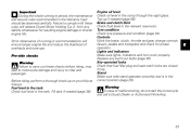
... needed (page 38). Brake and clutch fluid Check fluid level in the sump through the sight glass. Key-operated locks Check that fuel filler plug and seat catch locks are closed firmly. Warning In case of running -in period, the maintenance and service rules recommended in the Warranty Card should be observed carefully. Engine oil level Check oil level in the relevant reservoirs. Controls Work the brake, clutch, throttle and gear change controls (levers, pedals and...
... needed (page 38). Brake and clutch fluid Check fluid level in the sump through the sight glass. Key-operated locks Check that fuel filler plug and seat catch locks are closed firmly. Warning In case of running -in period, the maintenance and service rules recommended in the Warranty Card should be observed carefully. Engine oil level Check oil level in the relevant reservoirs. Controls Work the brake, clutch, throttle and gear change controls (levers, pedals and...

Owners Manual
Page 108
... in neutral. Warning Before starting the bike with a gear engaged, pull the clutch lever (in this case the side stand must be up (in a horizontal position) as its safety sensor prevents engine start the engine with the controls you will need to ON (fig. 26). Important The oil pressure light should go out a few seconds after the engine has started , the system prevents the starter motor from turning over...
... in neutral. Warning Before starting the bike with a gear engaged, pull the clutch lever (in this case the side stand must be up (in a horizontal position) as its safety sensor prevents engine start the engine with the controls you will need to ON (fig. 26). Important The oil pressure light should go out a few seconds after the engine has started , the system prevents the starter motor from turning over...

Owners Manual
Page 111
... may lock the wheels and lose control of the motorcycle. Braking Slow down in time, shift down gears to engine-brake first and then brake applying both brake lever and pedal for effective braking. When riding in a bend. When tackling long, high-gradient downhill road tracts, shift down to use brake controls harshly or violently or you less braking power. E 37 Never use engine braking. Using only one brake at a time and...
... may lock the wheels and lose control of the motorcycle. Braking Slow down in time, shift down gears to engine-brake first and then brake applying both brake lever and pedal for effective braking. When riding in a bend. When tackling long, high-gradient downhill road tracts, shift down to use brake controls harshly or violently or you less braking power. E 37 Never use engine braking. Using only one brake at a time and...

Owners Manual
Page 124
Release the clip (3, fig. 46) that lighting device (page 67). Detach connector (2, fig. 46) from headlight bulb. Replacing bulbs Before replacing a burnt-out bulb, make sure that the new one complies with voltage and wattage as specified on the Electric System for that holds the bulb in place and take the bulb out of its socket. 1 E fig. 45 3 2 fig. 46 50 Headlight (fig. 45, fig. 46, fig. 47, fig. 48) Loosen the lower screw (1) securing the rim/reflector unit to the body to gain access to the headlight bulbs.
Release the clip (3, fig. 46) that lighting device (page 67). Detach connector (2, fig. 46) from headlight bulb. Replacing bulbs Before replacing a burnt-out bulb, make sure that the new one complies with voltage and wattage as specified on the Electric System for that holds the bulb in place and take the bulb out of its socket. 1 E fig. 45 3 2 fig. 46 50 Headlight (fig. 45, fig. 46, fig. 47, fig. 48) Loosen the lower screw (1) securing the rim/reflector unit to the body to gain access to the headlight bulbs.

Owners Manual
Page 128
... adjust it whenever you are cold. Warning A tyre must be replaced when punctured. Never use tube type tyres. Important Do not remove or shift the wheel balancing weights. cm As tyre pressure is affected by 0.2 - 0.3 bar. If you find low pressure on bumpy roads, increase tyre pressure by temperature and altitude variations, you are advised to keep air inside. Important Check and...
... adjust it whenever you are cold. Warning A tyre must be replaced when punctured. Never use tube type tyres. Important Do not remove or shift the wheel balancing weights. cm As tyre pressure is affected by 0.2 - 0.3 bar. If you find low pressure on bumpy roads, increase tyre pressure by temperature and altitude variations, you are advised to keep air inside. Important Check and...

Owners Manual
Page 133
... for purposes of maintenance, repair or replacement, of any device or element of design incorporated into the cylinders through the spark plug seats, then crank the engine by hand a few times so a protective film of noise control prior to its seal and empty the fuel tank; Battery should be left unridden for over long periods, it is prohibited. It is the Owner's responsibility to the...
... for purposes of maintenance, repair or replacement, of any device or element of design incorporated into the cylinders through the spark plug seats, then crank the engine by hand a few times so a protective film of noise control prior to its seal and empty the fuel tank; Battery should be left unridden for over long periods, it is prohibited. It is the Owner's responsibility to the...
Owners Manual
Page 140
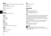
Shock absorber stroke: 65 mm. E Wheels Three-spoke, light-alloy rims. Front Make: BREMBO Dimensions: MT3.50x17" Rear Make: BREMBO Dimensions: MT4.50x17" Both wheel shafts can be removed. Size: 160/60-ZR17 Suspensions Front Hydraulic upside-down fork. Stanchion tubes diameter: 43 mm. Its bottom end pivots on each side): 27° Steering head angle: 24° Trail mm: 96 Rear Tubeless...
Shock absorber stroke: 65 mm. E Wheels Three-spoke, light-alloy rims. Front Make: BREMBO Dimensions: MT3.50x17" Rear Make: BREMBO Dimensions: MT4.50x17" Both wheel shafts can be removed. Size: 160/60-ZR17 Suspensions Front Hydraulic upside-down fork. Stanchion tubes diameter: 43 mm. Its bottom end pivots on each side): 27° Steering head angle: 24° Trail mm: 96 Rear Tubeless...

Owners Manual
Page 142
... side of the battery (fig. 58) protects the electronic regulator. Remove the fuse cap (3) to avoid possible short circuits. Failure to observe this rule may damage the electric system or even lead to fire. 2 1 fig. 58 4 4 IN GOOD CONDITION BLOWN fig. 59 68 Warning Never use a fuse with a rating other than specified. Mounting position and ampere capacity are connected. A blown fuse is located...
... side of the battery (fig. 58) protects the electronic regulator. Remove the fuse cap (3) to avoid possible short circuits. Failure to observe this rule may damage the electric system or even lead to fire. 2 1 fig. 58 4 4 IN GOOD CONDITION BLOWN fig. 59 68 Warning Never use a fuse with a rating other than specified. Mounting position and ampere capacity are connected. A blown fuse is located...

Owners Manual
Page 143
... 5) Fuse box 6) Starter motor 7) Solenoid starter 8) Battery 9) Regulator fuse 10) Regulator 11) Generator 12) RH rear turn indicator 13) Tail light 14) Number plate light 15) LH rear turn indicator 16) Fuel tank 17) Self-diagnosis connector 18) Speed sensor 19) Horizontal cylinder coil 20) Vertical cylinder coil 21) Horizontal cylinder spark plug 22) Vertical cylinder spark plug 23) Horizontal cylinder injector 24) Vertical cylinder injector 25) Throttle position sensor 26) Timing/rpm sensor 27) Side stand switch 28) ECU 5.9 M 29) Injection relay 30) Neutral switch 31) Oil pressure switch 32...
... 5) Fuse box 6) Starter motor 7) Solenoid starter 8) Battery 9) Regulator fuse 10) Regulator 11) Generator 12) RH rear turn indicator 13) Tail light 14) Number plate light 15) LH rear turn indicator 16) Fuel tank 17) Self-diagnosis connector 18) Speed sensor 19) Horizontal cylinder coil 20) Vertical cylinder coil 21) Horizontal cylinder spark plug 22) Vertical cylinder spark plug 23) Horizontal cylinder injector 24) Vertical cylinder injector 25) Throttle position sensor 26) Timing/rpm sensor 27) Side stand switch 28) ECU 5.9 M 29) Injection relay 30) Neutral switch 31) Oil pressure switch 32...
Owners Manual
Page 146
... the vehicle inspected and repaired by your local Ducati dealer. This product should be checked for the purpose of noise control prior to its sale or delivery to the ultimate purchaser or while it is in use; Rough idle. Crankcase Emission Control System The engine is separate from the throttle body and fuel tank. Poor performance (driveability) and poor economy. 72 Tampering warning Tampering...
... the vehicle inspected and repaired by your local Ducati dealer. This product should be checked for the purpose of noise control prior to its sale or delivery to the ultimate purchaser or while it is in use; Rough idle. Crankcase Emission Control System The engine is separate from the throttle body and fuel tank. Poor performance (driveability) and poor economy. 72 Tampering warning Tampering...

Owners Manual
Page 147
... fuel tank with its operation and handling characteristics under these conditions. Avoiding unnecessary weaving is plenty of both the front and rear brakes. Warning Before starting engine, check for proper operation of control. When going up steep slopes, shift to a lower gear so that there is important to control vehicle speed and less on loose roadway surfaces, the ability to avoid skidding the rear wheel from overreving. The throttle...
... fuel tank with its operation and handling characteristics under these conditions. Avoiding unnecessary weaving is plenty of both the front and rear brakes. Warning Before starting engine, check for proper operation of control. When going up steep slopes, shift to a lower gear so that there is important to control vehicle speed and less on loose roadway surfaces, the ability to avoid skidding the rear wheel from overreving. The throttle...
Owners Manual
Page 150
.... Engine family : This vehicle conforms to all applicable Federal Motor Vehicle Safety standards in & ex): See Service Manual Closing 0.03 - 0.12 mm SPARK PLUG: CHAMPION RA4HC SPARK PLUG GAP (mm): 0.5 0.6 OIL: SAE 20W50 FUEL: Unleaded gasoline INSTRUCTIONS No adjustment No adjustment No adjustment HOT AIR INLET HOLDING Via A.C.Ducati,3 40132 BOLOGNA ITALY CANISTER ITEM IGNITION TIMING: IDLE SPEED (RPM): IDLE MIXTURE: TO HORIZONTAL MANIFOLD TO VERTICAL MANIFOLD 4 5 HOLDING - EPA AND CALIFORNIA REGULATIONS...
.... Engine family : This vehicle conforms to all applicable Federal Motor Vehicle Safety standards in & ex): See Service Manual Closing 0.03 - 0.12 mm SPARK PLUG: CHAMPION RA4HC SPARK PLUG GAP (mm): 0.5 0.6 OIL: SAE 20W50 FUEL: Unleaded gasoline INSTRUCTIONS No adjustment No adjustment No adjustment HOT AIR INLET HOLDING Via A.C.Ducati,3 40132 BOLOGNA ITALY CANISTER ITEM IGNITION TIMING: IDLE SPEED (RPM): IDLE MIXTURE: TO HORIZONTAL MANIFOLD TO VERTICAL MANIFOLD 4 5 HOLDING - EPA AND CALIFORNIA REGULATIONS...
Owners Manual
Page 151
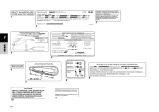
... In the event of 12,000 kilometers (7,456 miles), if the motorcycle's engine displacement is equal to conform at the time of initial retail purchase with all applicable regulations of initial retail delivery, whichever first occurs. CANISTER Ducati limited warranty on the engine displacement,of fuel system malfunction, contact Ducati's authorized Service Centres. California evaporation emission system (fig.
... In the event of 12,000 kilometers (7,456 miles), if the motorcycle's engine displacement is equal to conform at the time of initial retail purchase with all applicable regulations of initial retail delivery, whichever first occurs. CANISTER Ducati limited warranty on the engine displacement,of fuel system malfunction, contact Ducati's authorized Service Centres. California evaporation emission system (fig.
Owners Manual
Page 152
... owner for evaporative emission controlled vehicles; These warranted parts are specifically defined by other services and adjustments required for routine maintenance. air cutoff valves; fuel/vapor separator; igniters; Coverage Warranty defects shall be required to keep receipts and failed parts in an emergency repair. intake manifold; Since emission related parts may not contain all warranted parts replaced and labor charges based on which adversely affect performance...
... owner for evaporative emission controlled vehicles; These warranted parts are specifically defined by other services and adjustments required for routine maintenance. air cutoff valves; fuel/vapor separator; igniters; Coverage Warranty defects shall be required to keep receipts and failed parts in an emergency repair. intake manifold; Since emission related parts may not contain all warranted parts replaced and labor charges based on which adversely affect performance...