

Owners Manual
Page 8
... ...Warning/Indicator Lights ...Service Code ...Keys ...Ignition Switch/Steering Lock ...Audio System ...Important Notice ...Operating Precautions ...Getting Started ...Radio Power On/Off...Radio (FM/AM/WX BAND)...9 13 14 17 20 20 21 22 23 29 31 34 35 36 39 39 39 43 44 44 PTT (Push to Talk) ...Left Handlebar Switches ...Dimmer Switch ...Turn Signal Switch...Horn Button ...Audio Control Switches ...Right Handlebar Switches...Hazard Switch ...Engine Stop Switch ...Starter Button ...Meter Unit Switch ...Electronic Cruise Control ON...
... ...Warning/Indicator Lights ...Service Code ...Keys ...Ignition Switch/Steering Lock ...Audio System ...Important Notice ...Operating Precautions ...Getting Started ...Radio Power On/Off...Radio (FM/AM/WX BAND)...9 13 14 17 20 20 21 22 23 29 31 34 35 36 39 39 39 43 44 44 PTT (Push to Talk) ...Left Handlebar Switches ...Dimmer Switch ...Turn Signal Switch...Horn Button ...Audio Control Switches ...Right Handlebar Switches...Hazard Switch ...Engine Stop Switch ...Starter Button ...Meter Unit Switch ...Electronic Cruise Control ON...

Owners Manual
Page 9
... Cruise Control Switch (SET/- Anti-lock Brake System (ABS) for models equipped with K-ACT ABS...K-ACT ABS Indicator Light ...Stopping the Engine...Stopping the Motorcycle in an Emergency ...Parking ...Catalytic Converter...Electronic Throttle Valve (ETV) System...SAFE OPERATION ...Safe Riding Technique ... 96 102 104 104 107 110 111 113 114 117 118 119 120 121 123 124 124 Starting the Engine ...Jump Starting ...Moving Off...Shifting Gears ...Braking ...Kawasaki Advanced Coactive-braking Technology...
... Cruise Control Switch (SET/- Anti-lock Brake System (ABS) for models equipped with K-ACT ABS...K-ACT ABS Indicator Light ...Stopping the Engine...Stopping the Motorcycle in an Emergency ...Parking ...Catalytic Converter...Electronic Throttle Valve (ETV) System...SAFE OPERATION ...Safe Riding Technique ... 96 102 104 104 107 110 111 113 114 117 118 119 120 121 123 124 124 Starting the Engine ...Jump Starting ...Moving Off...Shifting Gears ...Braking ...Kawasaki Advanced Coactive-braking Technology...

Owners Manual
Page 10
... Periodic Maintenance Chart...Engine Oil ...Cooling System ...Drive Belt...Spark Plugs...Evaporative Emission Control System (California model only) ...Valve Clearance ...Kawasaki Clean Air System ...Air Cleaner ...Throttle Control System ...Idle Speed ...Clutch ...Brakes ... 127 130 132 136 149 156 162 163 164 165 165 166 169 170 174 175 Brake Light Switches...Rear Shock Absorbers ...Wheels ...Battery...Headlight Beam...Fuses ...General Lubrication...Cleaning Your Motorcycle ...Bolt and Nut Tightening...STORAGE ...TROUBLESHOOTING GUIDE...YOUR WARRANTY/OWNER SATISFACTION ...REPORTING SAFETY...
... Periodic Maintenance Chart...Engine Oil ...Cooling System ...Drive Belt...Spark Plugs...Evaporative Emission Control System (California model only) ...Valve Clearance ...Kawasaki Clean Air System ...Air Cleaner ...Throttle Control System ...Idle Speed ...Clutch ...Brakes ... 127 130 132 136 149 156 162 163 164 165 165 166 169 170 174 175 Brake Light Switches...Rear Shock Absorbers ...Wheels ...Battery...Headlight Beam...Fuses ...General Lubrication...Cleaning Your Motorcycle ...Bolt and Nut Tightening...STORAGE ...TROUBLESHOOTING GUIDE...YOUR WARRANTY/OWNER SATISFACTION ...REPORTING SAFETY...

Owners Manual
Page 21
... such accessories will not be remedied under warranty. Fairings, windshields, backrests, and other aspect of the motorcycle's operation. 7. Kawasaki does not manufacture sidecars or trailers for the results of such unintended use of such accessories on handling or stability, but also due to the aerodynamic forces acting on motorcycle components caused by the use of the steering assembly and...
... such accessories will not be remedied under warranty. Fairings, windshields, backrests, and other aspect of the motorcycle's operation. 7. Kawasaki does not manufacture sidecars or trailers for the results of such unintended use of such accessories on handling or stability, but also due to the aerodynamic forces acting on motorcycle components caused by the use of the steering assembly and...
Owners Manual
Page 34
... right, the right turn signal indicator light starts flashing. : When the headlight is on high beam, the high beam indicator light goes on. (For models equipped with the K-ACT ABS, the indicator goes on , the K-ACT ABS does not function but the ABS functions. For more detailed information about K-ACT ABS, see the Kawasaki Advanced Coactive-braking Technology (K-ACT) Anti-lock Brake System (ABS) section in...
... right, the right turn signal indicator light starts flashing. : When the headlight is on high beam, the high beam indicator light goes on. (For models equipped with the K-ACT ABS, the indicator goes on , the K-ACT ABS does not function but the ABS functions. For more detailed information about K-ACT ABS, see the Kawasaki Advanced Coactive-braking Technology (K-ACT) Anti-lock Brake System (ABS) section in...

Owners Manual
Page 39
... be shifted to, by push down and turn on whenever the ignition switch is released after turning the ignition key to the left for • Turn locking the steering lock. are on the ignition key. ACC ON A. Ignition Switch B. Engine on when the starter button is in the ON position. Engine off . Audio system, accessory socket, accessory connector, fog light, hazard light equipment can be used . To avoid battery discharge, always start the engine immediately after starting the engine. ACC...
... be shifted to, by push down and turn on whenever the ignition switch is released after turning the ignition key to the left for • Turn locking the steering lock. are on the ignition key. ACC ON A. Ignition Switch B. Engine on when the starter button is in the ON position. Engine off . Audio system, accessory socket, accessory connector, fog light, hazard light equipment can be used . To avoid battery discharge, always start the engine immediately after starting the engine. ACC...

Owners Manual
Page 86
Pull up the rear of the rider's seat to clear the hold portions, and then pull the seat to the rear. • • Rider's Seat Installation To install the rider's seat, insert the tab at the holder and engage the two grommet holes onto the two projections. • 84 GENERAL INFORMATION A. Hold Portions Rider's Seat Removal Remove the passenger's seat. Front A. Rider's Seat B. Passenger's Seat B.
Pull up the rear of the rider's seat to clear the hold portions, and then pull the seat to the rear. • • Rider's Seat Installation To install the rider's seat, insert the tab at the holder and engage the two grommet holes onto the two projections. • 84 GENERAL INFORMATION A. Hold Portions Rider's Seat Removal Remove the passenger's seat. Front A. Rider's Seat B. Passenger's Seat B.

Owners Manual
Page 87
Tab Holder Holes Projections Passenger's Seat Installation Insert the tab on the rear of the passenger's seat into the left and right projections at the front of the passenger's seat into the slot on the frame. • • A. Insert the left and right holes on the rear fender. B. D. GENERAL INFORMATION 85 down the front part of • Pull the passenger's and rider's seats to make sure they are securely locked. D. Tab Holder Projections Holes up the front and rear ends of the pas• Push senger's seat until the lock clicks. C. A. B. C.
Tab Holder Holes Projections Passenger's Seat Installation Insert the tab on the rear of the passenger's seat into the left and right projections at the front of the passenger's seat into the slot on the frame. • • A. Insert the left and right holes on the rear fender. B. D. GENERAL INFORMATION 85 down the front part of • Pull the passenger's and rider's seats to make sure they are securely locked. D. Tab Holder Projections Holes up the front and rear ends of the pas• Push senger's seat until the lock clicks. C. A. B. C.

Owners Manual
Page 113
... the vehicle speeds shown in the table in the clutch lever. The transmission will shift only into the next higher or lower gear. the throttle half way, while re• Open leasing the clutch lever. When shifting down when the motorcycle is standing still, the transmission cannot be shifted past neutral from 1st gear. NOTE żThe transmission is equipped with a WARNING Downshifting at such a high speed that engine...
... the vehicle speeds shown in the table in the clutch lever. The transmission will shift only into the next higher or lower gear. the throttle half way, while re• Open leasing the clutch lever. When shifting down when the motorcycle is standing still, the transmission cannot be shifted past neutral from 1st gear. NOTE żThe transmission is equipped with a WARNING Downshifting at such a high speed that engine...

Owners Manual
Page 119
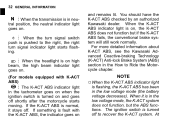
... ABS fails, the front and rear brakes work normally as a conventional brake system. The front or rear wheel races.) In this operation, but if K-ACT ABS indicator light remains lit after the motor• The cycle starts moving . light remains lit after the motorcycle runs at the speed of the following, a fault or faults may have the K-ACT ABS checked by this case, first turn the ignition key...
... ABS fails, the front and rear brakes work normally as a conventional brake system. The front or rear wheel races.) In this operation, but if K-ACT ABS indicator light remains lit after the motor• The cycle starts moving . light remains lit after the motorcycle runs at the speed of the following, a fault or faults may have the K-ACT ABS checked by this case, first turn the ignition key...

Owners Manual
Page 130
Engine stop switch ...Stops engine. Nuts, bolts, fasteners .. Check that steering and suspension components, axles, and all controls are properly tightened or fastened. Electrical equipment ...All lights and horn work. Coolant ...No coolant leakage. No binding of control cables. Side stand ...Returns to lock. Coolant level between level lines (when engine is cold). Return spring not weak or not damaged. Brakes ...Brake pad wear: Lining thickness more than 1 mm (0.04 in .). Steering ...Action smooth but...
Engine stop switch ...Stops engine. Nuts, bolts, fasteners .. Check that steering and suspension components, axles, and all controls are properly tightened or fastened. Electrical equipment ...All lights and horn work. Coolant ...No coolant leakage. No binding of control cables. Side stand ...Returns to lock. Coolant level between level lines (when engine is cold). Return spring not weak or not damaged. Brakes ...Brake pad wear: Lining thickness more than 1 mm (0.04 in .). Steering ...Action smooth but...

Owners Manual
Page 142
inspect Clutch fluid level - Periodic Inspection (Chassis Related Items) Frequency Whichever comes first *Odometer Reading km × 1000 (mile × 1000) See Page Operation (Chassis Items) Clutch operation (play, engagement, disengagement) - inspect Every 1 6 12 18 24 30 36 (0.6) (3.75) (7.5) (11.25) (15) (18.75) (22.5) Clutch and drive train: • 6 months year year 174 • • • 174 - - inspect Clutch fluid leak inspect Clutch hose damage - 140 MAINTENANCE AND ADJUSTMENT 2.
inspect Clutch fluid level - Periodic Inspection (Chassis Related Items) Frequency Whichever comes first *Odometer Reading km × 1000 (mile × 1000) See Page Operation (Chassis Items) Clutch operation (play, engagement, disengagement) - inspect Every 1 6 12 18 24 30 36 (0.6) (3.75) (7.5) (11.25) (15) (18.75) (22.5) Clutch and drive train: • 6 months year year 174 • • • 174 - - inspect Clutch fluid leak inspect Clutch hose damage - 140 MAINTENANCE AND ADJUSTMENT 2.

Owners Manual
Page 145
MAINTENANCE AND ADJUSTMENT 143 Frequency Whichever comes first *Odometer Reading km × 1000 (mile × 1000) See Page Operation (Chassis Items) Brake hose installation condition inspect Every 1 6 12 18 24 30 36 (0.6) (3.75) (7.5) (11.25) (15) (18.75) (22.5) year 176 Brake fluid level 6 months inspect Brake operation (effectiveness, play, drag) inspect Brake light switch operation inspect year 176 179 180
MAINTENANCE AND ADJUSTMENT 143 Frequency Whichever comes first *Odometer Reading km × 1000 (mile × 1000) See Page Operation (Chassis Items) Brake hose installation condition inspect Every 1 6 12 18 24 30 36 (0.6) (3.75) (7.5) (11.25) (15) (18.75) (22.5) year 176 Brake fluid level 6 months inspect Brake operation (effectiveness, play, drag) inspect Brake light switch operation inspect year 176 179 180

Owners Manual
Page 151
... used too long. MAINTENANCE AND ADJUSTMENT 149 Engine Oil In order for the engine, transmission, and clutch to function properly, maintain the engine oil at the proper level, and change the oil according to the periodic maintenance chart in the Owner's Manual. • Not only do dirt and metal particles collect in engine or transmission seizure, accident, and injury. Because of the engine oil level, follow the...
... used too long. MAINTENANCE AND ADJUSTMENT 149 Engine Oil In order for the engine, transmission, and clutch to function properly, maintain the engine oil at the proper level, and change the oil according to the periodic maintenance chart in the Owner's Manual. • Not only do dirt and metal particles collect in engine or transmission seizure, accident, and injury. Because of the engine oil level, follow the...

Owners Manual
Page 156
Start the engine. NOTE żReplace any gaskets with • Install new gaskets and tighten them to the specified torque. Packing the engine oil drain bolts with new ones. Tightening Torque Engine Oil Drain Bolts: 20 N·m (2.0 kgf·m, 15 ft·lb) Oil Filter: 18 N·m (1.8 kgf·m, 13 ft·lb) A. 154 MAINTENANCE AND ADJUSTMENT a thin film of oil to the packing • Apply...
Start the engine. NOTE żReplace any gaskets with • Install new gaskets and tighten them to the specified torque. Packing the engine oil drain bolts with new ones. Tightening Torque Engine Oil Drain Bolts: 20 N·m (2.0 kgf·m, 15 ft·lb) Oil Filter: 18 N·m (1.8 kgf·m, 13 ft·lb) A. 154 MAINTENANCE AND ADJUSTMENT a thin film of oil to the packing • Apply...

Owners Manual
Page 182
...; A. The front brake light switch requires no adjustment, but the rear brake light switch should go on . Brake Pedal B. 10 mm (0.4 in accordance with the Periodic Maintenance Chart. the operation of the rear brake • Check light switch by depressing the brake pedal. The brake light should be adjusted in .) 180 MAINTENANCE AND ADJUSTMENT Brake Light Switches When either the front or rear brake is applied. Inspection Turn the ignition key to inspect the front brake light switch.
...; A. The front brake light switch requires no adjustment, but the rear brake light switch should go on . Brake Pedal B. 10 mm (0.4 in accordance with the Periodic Maintenance Chart. the operation of the rear brake • Check light switch by depressing the brake pedal. The brake light should be adjusted in .) 180 MAINTENANCE AND ADJUSTMENT Brake Light Switches When either the front or rear brake is applied. Inspection Turn the ignition key to inspect the front brake light switch.

Owners Manual
Page 183
NOTICE To avoid damaging the electrical connections inside the switch, be sure that the switch body does not turn during adjustment. C. Lights Later. B. D. Rear Brake Light Switch Adjusting Nut Lights Sooner. MAINTENANCE AND ADJUSTMENT 181 the light does not go on, adjust the • If rear brake light switch. Brake Pedal Travel 10 mm (0.4 in.) Adjustment To adjust the rear brake light switch, move the switch up or down by turning the adjusting nut. • A.
NOTICE To avoid damaging the electrical connections inside the switch, be sure that the switch body does not turn during adjustment. C. Lights Later. B. D. Rear Brake Light Switch Adjusting Nut Lights Sooner. MAINTENANCE AND ADJUSTMENT 181 the light does not go on, adjust the • If rear brake light switch. Brake Pedal Travel 10 mm (0.4 in.) Adjustment To adjust the rear brake light switch, move the switch up or down by turning the adjusting nut. • A.

Owners Manual
Page 203
MAINTENANCE AND ADJUSTMENT 201 A. Normal B. NOTICE Do not remove the battery and fuse for the standard fuse. Main Fuse A. Do not use any substitute for 6 seconds after turning off the ignition switch. Replace the blown fuse with a new one of the correct capacity, as specified on the junction box and main fuse. Failed WARNING Substituting fuses can cause wiring to overheat, catch fire and/or fail.
MAINTENANCE AND ADJUSTMENT 201 A. Normal B. NOTICE Do not remove the battery and fuse for the standard fuse. Main Fuse A. Do not use any substitute for 6 seconds after turning off the ignition switch. Replace the blown fuse with a new one of the correct capacity, as specified on the junction box and main fuse. Failed WARNING Substituting fuses can cause wiring to overheat, catch fire and/or fail.

Owners Manual
Page 206
... and around the vehicle chassis, engine, and exhaust can cause mechanical problems and increase the risk of fire. applying degreaser to collect in conditions that allow debris or flammable material to seals, • Avoid brake pads, and tires. Gasoline, brake fluid, and coolant will damage the finish of painted and plastic surfaces: wash them off immediately. Use care when washing the windshield, headlight cover, and the...
... and around the vehicle chassis, engine, and exhaust can cause mechanical problems and increase the risk of fire. applying degreaser to collect in conditions that allow debris or flammable material to seals, • Avoid brake pads, and tires. Gasoline, brake fluid, and coolant will damage the finish of painted and plastic surfaces: wash them off immediately. Use care when washing the windshield, headlight cover, and the...

Owners Manual
Page 214
Rear Shock Absorber Mounting Nuts 22. Rear Guard Mounting Bolts 26. Front Guard Mounting Bolts Brake Pedal Mounting Bolt 28. Rear Fender Mounting Bolts 21. Downtube Bolts 24. Pivot Shaft Nut 27. Muffler Mounting Bolts 23. 212 MAINTENANCE AND ADJUSTMENT 20. Rear Axle Nut 25.
Rear Shock Absorber Mounting Nuts 22. Rear Guard Mounting Bolts 26. Front Guard Mounting Bolts Brake Pedal Mounting Bolt 28. Rear Fender Mounting Bolts 21. Downtube Bolts 24. Pivot Shaft Nut 27. Muffler Mounting Bolts 23. 212 MAINTENANCE AND ADJUSTMENT 20. Rear Axle Nut 25.
