

Owners Manual
Page 16
... your passenger. Towing a trailer can make the motorcycle hard to handle. S If necessary, adjust the rear shock absorber preload according to keep both feet firmly on properly, or who is not holding on the passenger footrests. Carrying a Passenger NOTE: Some models are not equipped from the factory with both hands and to the instructions on the passenger footrests. Discuss any safety information...
... your passenger. Towing a trailer can make the motorcycle hard to handle. S If necessary, adjust the rear shock absorber preload according to keep both feet firmly on properly, or who is not holding on the passenger footrests. Carrying a Passenger NOTE: Some models are not equipped from the factory with both hands and to the instructions on the passenger footrests. Discuss any safety information...

Owners Manual
Page 22
... operator or passengers, as well as towing will impair the motorcycle's steering and handling, which can also damage the motorcycle's finish. Place tie-downs around both sides of the motorcycle with another vehicle, as damage to avoid the brake line, exhaust, and drive belt. Transporting the Motorcycle If you must transport the motorcycle: S Use a truck or trailer. Secure the rear of the...
... operator or passengers, as well as towing will impair the motorcycle's steering and handling, which can also damage the motorcycle's finish. Place tie-downs around both sides of the motorcycle with another vehicle, as damage to avoid the brake line, exhaust, and drive belt. Transporting the Motorcycle If you must transport the motorcycle: S Use a truck or trailer. Secure the rear of the...
Owners Manual
Page 25
... or rear suspension system can make the motorcycle hard to handle and cause loss of control. Check for tire replacement. Inspect tires regularly and replace them if they're worn or damaged. S Check proper steering head bearing adjustment. To repair steering or suspension system wear or damage, see the VICTORY Service Manual or your authorized VICTORY Dealer. 20 Operating the motorcycle with improper tire pressure or tread condition...
... or rear suspension system can make the motorcycle hard to handle and cause loss of control. Check for tire replacement. Inspect tires regularly and replace them if they're worn or damaged. S Check proper steering head bearing adjustment. To repair steering or suspension system wear or damage, see the VICTORY Service Manual or your authorized VICTORY Dealer. 20 Operating the motorcycle with improper tire pressure or tread condition...

Owners Manual
Page 36
Front Fork Front Turn Signal Headlight Air Filter Spark Plug (2) Ignition Switch Left Side Cover Battery (under side cover) Heated Grip Switch Rear Turn Signal Taillight Rear Axle Adjuster (1 each side) Rear Brake Caliper Passenger's Foot Rest Evaporative Emissions Canister (California Models) (lower left by swingarm) Oil Filter Oil Drain Plug (under engine) Sidestand Operator's Foot Rest Gear Shift Lever Horn Front Brake Caliper 2 1 COMPONENT IDENTIFICATION 3 4 5 6 8 9 10 11 7 12 22 21 20 19 18 17 16 15 14 13 31 LEFT SIDE VIEW 1. 2. 3. 4. 5. 6. 7. 8. 9. 10...
Front Fork Front Turn Signal Headlight Air Filter Spark Plug (2) Ignition Switch Left Side Cover Battery (under side cover) Heated Grip Switch Rear Turn Signal Taillight Rear Axle Adjuster (1 each side) Rear Brake Caliper Passenger's Foot Rest Evaporative Emissions Canister (California Models) (lower left by swingarm) Oil Filter Oil Drain Plug (under engine) Sidestand Operator's Foot Rest Gear Shift Lever Horn Front Brake Caliper 2 1 COMPONENT IDENTIFICATION 3 4 5 6 8 9 10 11 7 12 22 21 20 19 18 17 16 15 14 13 31 LEFT SIDE VIEW 1. 2. 3. 4. 5. 6. 7. 8. 9. 10...

Owners Manual
Page 40
... be removed. Ignition Key INSTRUMENTS, FEATURES AND CONTROLS The ignition key operates the ignition switch and parking lights. P (Park) illuminate. Ignition Switch The ignition switch energizes the ignition, the lighting system, and all other electrical features. On 3. The headlight, taillight, and instrument lights 2. On Position In the ON position, all electrical circuits are inactive and the ignition key can also activate the emergency flashers, turn signals and all electrical switches and buttons. You must push the ignition key into the switch while selecting...
... be removed. Ignition Key INSTRUMENTS, FEATURES AND CONTROLS The ignition key operates the ignition switch and parking lights. P (Park) illuminate. Ignition Switch The ignition switch energizes the ignition, the lighting system, and all other electrical features. On 3. The headlight, taillight, and instrument lights 2. On Position In the ON position, all electrical circuits are inactive and the ignition key can also activate the emergency flashers, turn signals and all electrical switches and buttons. You must push the ignition key into the switch while selecting...
Owners Manual
Page 46
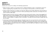
... clutch, gradually release the lever. Momentary Feature: Move the turn signal switch left turn signals. A signal will then cancel when the switch is released. To sound the horn, press the horn button. Horn Button (4) Clutch Lever (5) To disengage the clutch, pull the lever (5) toward the handlebar. Left Handlebar Controls INSTRUMENTS, FEATURES AND CONTROLS Turn Signal Switch Operation (3) The ignition key must be in the ON or PARK position and the engine stop/run switch must be in gear and the clutch...
... clutch, gradually release the lever. Momentary Feature: Move the turn signal switch left turn signals. A signal will then cancel when the switch is released. To sound the horn, press the horn button. Horn Button (4) Clutch Lever (5) To disengage the clutch, pull the lever (5) toward the handlebar. Left Handlebar Controls INSTRUMENTS, FEATURES AND CONTROLS Turn Signal Switch Operation (3) The ignition key must be in the ON or PARK position and the engine stop/run switch must be in gear and the clutch...
Owners Manual
Page 47
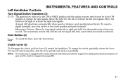
... in the STOP position. Engine Stop/Run Switch 2. Starter Button 1 Starter Button (2) The starter button works only when the engine stop /run switch completes or interrupts the ignition, starter, and fuel pump circuits. The engine should not start and run, press the lower portion of the engine stop /run switch is in the RUN position and the transmission is in neutral or the clutch is in toward handlebar.) To engage the engine starter motor, press the right side...
... in the STOP position. Engine Stop/Run Switch 2. Starter Button 1 Starter Button (2) The starter button works only when the engine stop /run switch completes or interrupts the ignition, starter, and fuel pump circuits. The engine should not start and run, press the lower portion of the engine stop /run switch is in the RUN position and the transmission is in neutral or the clutch is in toward handlebar.) To engage the engine starter motor, press the right side...

Owners Manual
Page 50
Fuel Cap INSTRUMENTS, FEATURES AND CONTROLS The fuel cap must be opened and closed with the ignition key. For fueling procedure, see Fueling and Fill Height, page 64. If tank was empty of fuel, prime the fuel pump. (See Fuel Pump Priming procedure on cap and insert key. S Maintain downward pressure on cap. S Remove key and close : S Turn key clockwise and press down lightly to release latch and open : S Lift key slot cover (1) on page 64.) To open the cap To close the key slot cover. 1 45 S Turn clockwise while pushing down on cap and turn key counterclockwise.
Fuel Cap INSTRUMENTS, FEATURES AND CONTROLS The fuel cap must be opened and closed with the ignition key. For fueling procedure, see Fueling and Fill Height, page 64. If tank was empty of fuel, prime the fuel pump. (See Fuel Pump Priming procedure on cap and insert key. S Maintain downward pressure on cap. S Remove key and close : S Turn key clockwise and press down lightly to release latch and open : S Lift key slot cover (1) on page 64.) To open the cap To close the key slot cover. 1 45 S Turn clockwise while pushing down on cap and turn key counterclockwise.
Owners Manual
Page 53
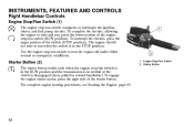
... slight pressure to the rear brake pedal; PRE-OPERATION CHECK Electrical Equipment To perform a pre-operation check on . Set the ignition switch to the high beam position. Taillight / Brake Light With the ignition switch in neutral, the neutral indicator should illuminate until the engine is started. taillight brightness should increase. 48 taillight brightness should increase. Indicator Lights The low oil pressure indicator should remain illuminated. Set the headlight switch to...
... slight pressure to the rear brake pedal; PRE-OPERATION CHECK Electrical Equipment To perform a pre-operation check on . Set the ignition switch to the high beam position. Taillight / Brake Light With the ignition switch in neutral, the neutral indicator should illuminate until the engine is started. taillight brightness should increase. 48 taillight brightness should increase. Indicator Lights The low oil pressure indicator should remain illuminated. Set the headlight switch to...

Owners Manual
Page 57
.... Refer to the top of your intended load. When the road contact surface has worn to the tire pressure table on page 119. Tire Condition Inspect the tire sidewalls, road contact surface, and tread base for the total weight of the wear bars, replace the tire. 52 Replace damaged tires immediately (see the VICTORY Service Manual or an authorized VICTORY dealer). For an accurate reading...
.... Refer to the top of your intended load. When the road contact surface has worn to the tire pressure table on page 119. Tire Condition Inspect the tire sidewalls, road contact surface, and tread base for the total weight of the wear bars, replace the tire. 52 Replace damaged tires immediately (see the VICTORY Service Manual or an authorized VICTORY dealer). For an accurate reading...

Owners Manual
Page 58
...distance, turn the adjuster to align a lower number to its rest position quickly when released. Indicator Mark 1 Front Brake Fluid Level 1. You should be clear and at a level in the lever within the first 3/4-inch (19 mm) of lever travel. The fluid should...brake fluid through the sight glass. Add brake fluid if necessary (see page 112). 53 Lever Reach Adjuster 2. S To increase reach distance, turn the adjuster to align a higher number to the hand grip) is level. 2. Lever reach (distance to the indicator mark on level ground with the front wheel straight forward. Brakes...
...distance, turn the adjuster to align a lower number to its rest position quickly when released. Indicator Mark 1 Front Brake Fluid Level 1. You should be clear and at a level in the lever within the first 3/4-inch (19 mm) of lever travel. The fluid should...brake fluid through the sight glass. Add brake fluid if necessary (see page 112). 53 Lever Reach Adjuster 2. S To increase reach distance, turn the adjuster to align a higher number to the hand grip) is level. 2. Lever reach (distance to the indicator mark on level ground with the front wheel straight forward. Brakes...
Owners Manual
Page 72
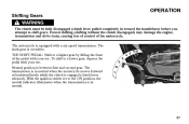
... gear. With the ignition switch set to a higher gear by lifting the front of the motorcycle. TOE SHIFT PEDAL: Shift to the ON position, the neutral indicator illuminates when the transmission is overdrive. The sixth gear is in neutral. To shift to shift gears. Forced shifting (shifting without the clutch disengaged) may damage the engine, transmission and drive train, causing loss of control of the pedal with your toe. Shifting Gears WARNING OPERATION The clutch...
... gear. With the ignition switch set to a higher gear by lifting the front of the motorcycle. TOE SHIFT PEDAL: Shift to the ON position, the neutral indicator illuminates when the transmission is overdrive. The sixth gear is in neutral. To shift to shift gears. Forced shifting (shifting without the clutch disengaged) may damage the engine, transmission and drive train, causing loss of control of the pedal with your toe. Shifting Gears WARNING OPERATION The clutch...

Owners Manual
Page 77
... the engine and the transmission or cause the rear wheel to lose traction. OPERATION Stopping the Engine Before stopping the engine, bring the motorcycle to a complete stop /run switch is turned off the road and away from traffic. 72 NOTE: Idle air control (IAC) noise is a normal engine management calibration process that occurs each time the engine stop , if it is not already in neutral or with the clutch...
... the engine and the transmission or cause the rear wheel to lose traction. OPERATION Stopping the Engine Before stopping the engine, bring the motorcycle to a complete stop /run switch is turned off the road and away from traffic. 72 NOTE: Idle air control (IAC) noise is a normal engine management calibration process that occurs each time the engine stop , if it is not already in neutral or with the clutch...

Owners Manual
Page 97
... adjuster screws or the nuts are turned OUT (counterclockwise) push the wheel and axle forward to turn at a time and monitor wheel alignment as you proceed. 5. Readjust if necessary until alignment is correct and drive belt tension is correct, tighten the adjuster lock nut (screw-style), then tighten the axle nut. MAINTENANCE Rear Wheel Alignment NOTE: Turn the axle adjusters about 1/16 of the swingarm...
... adjuster screws or the nuts are turned OUT (counterclockwise) push the wheel and axle forward to turn at a time and monitor wheel alignment as you proceed. 5. Readjust if necessary until alignment is correct and drive belt tension is correct, tighten the adjuster lock nut (screw-style), then tighten the axle nut. MAINTENANCE Rear Wheel Alignment NOTE: Turn the axle adjusters about 1/16 of the swingarm...

Owners Manual
Page 103
... at the front of the ground. With the transmission in the operator's seat and slowly bounce the rear suspension a few times. Inspect Swing Arm and Rear Axle 1. MAINTENANCE Rear Suspension WARNING Care should be taken to -side. Use an appropriate motorcycle lift or a block of the motorcycle until the rear wheel is movement at the rear axle, inspect the wheel bearings and rear axle (see the VICTORY Service Manual or an authorized VICTORY dealer...
... at the front of the ground. With the transmission in the operator's seat and slowly bounce the rear suspension a few times. Inspect Swing Arm and Rear Axle 1. MAINTENANCE Rear Suspension WARNING Care should be taken to -side. Use an appropriate motorcycle lift or a block of the motorcycle until the rear wheel is movement at the rear axle, inspect the wheel bearings and rear axle (see the VICTORY Service Manual or an authorized VICTORY dealer...

Owners Manual
Page 105
...The steering head bearings require periodic lubrication even if there is movement at the steering head when checked. 4. Slowly rotate the front wheel. Use an appropriate motorcycle lift or a block of the ground. Grasp the front tire and attempt to move the front wheel front...the front axle, inspect the wheel bearings and front axle (see the VICTORY Service Manual or an authorized VICTORY dealer). 100 MAINTENANCE WARNING Front Suspension and Steering Care should be taken to be smooth but not loose or interfered with by wires, hoses, or control cables. 3. Inspect Steering and Front...
...The steering head bearings require periodic lubrication even if there is movement at the steering head when checked. 4. Slowly rotate the front wheel. Use an appropriate motorcycle lift or a block of the ground. Grasp the front tire and attempt to move the front wheel front...the front axle, inspect the wheel bearings and front axle (see the VICTORY Service Manual or an authorized VICTORY dealer). 100 MAINTENANCE WARNING Front Suspension and Steering Care should be taken to be smooth but not loose or interfered with by wires, hoses, or control cables. 3. Inspect Steering and Front...

Owners Manual
Page 107
... both release buttons (3) simultaneously. For fuel filter replacement procedures and special tools required, see the VICTORY Service Manual or contact an authorized VICTORY dealer. 102 Carefully remove the fuel tank. Reinstall the seat. 2 Fuel Filter Replacement The fuel filters are attached to catch dripping fuel in an appropriate container. 7. Disconnect it click. 9. At the rear left side of breather hose. 8. Be prepared to the electric fuel pump located inside the fuel tank. MAINTENANCE Fuel...
... both release buttons (3) simultaneously. For fuel filter replacement procedures and special tools required, see the VICTORY Service Manual or contact an authorized VICTORY dealer. 102 Carefully remove the fuel tank. Reinstall the seat. 2 Fuel Filter Replacement The fuel filters are attached to catch dripping fuel in an appropriate container. 7. Disconnect it click. 9. At the rear left side of breather hose. 8. Be prepared to the electric fuel pump located inside the fuel tank. MAINTENANCE Fuel...
Owners Manual
Page 153
... centimeters; Limited Warranty on the engine displacement, of the United States Environmental Protection Agency, and the California Air Resources Board; or of initial retail delivery, whichever occurs first. 148 The warranty repairs should be aware that includes as a problem exists. and B. or 5 (five) years from defects in a reasonable amount of the required maintenance listed in your owner's manual. If...
... centimeters; Limited Warranty on the engine displacement, of the United States Environmental Protection Agency, and the California Air Resources Board; or of initial retail delivery, whichever occurs first. 148 The warranty repairs should be aware that includes as a problem exists. and B. or 5 (five) years from defects in a reasonable amount of the required maintenance listed in your owner's manual. If...

Owners Manual
Page 164
SPECIFICATIONS Model Year 2009 Wheels and Tires Front Wheel Type/Size Rear Wheel Type Size Front Tire Type/Size Rear Tire Type/Size Electrical Alternator Battery Lights and Fuses Fuses Engine / ECM Fuel Pump Headlight / Brake Light Lamps Tail Light Lamps / Flashers / Indicator Lamps / Horn Ignition / Gauges Accessory Bulbs Headlight (International) Taillight Turn Signal Indicator 15 amp 10 amp 20 amp 15 amp 15 amp 15 amp High H11 / Low H11 Non-Serviceable LED R10W 2.3 Watt Wedge Base 38 Amp Max Output 12 Volts 18 Amp Hour Cast 18...
SPECIFICATIONS Model Year 2009 Wheels and Tires Front Wheel Type/Size Rear Wheel Type Size Front Tire Type/Size Rear Tire Type/Size Electrical Alternator Battery Lights and Fuses Fuses Engine / ECM Fuel Pump Headlight / Brake Light Lamps Tail Light Lamps / Flashers / Indicator Lamps / Horn Ignition / Gauges Accessory Bulbs Headlight (International) Taillight Turn Signal Indicator 15 amp 10 amp 20 amp 15 amp 15 amp 15 amp High H11 / Low H11 Non-Serviceable LED R10W 2.3 Watt Wedge Base 38 Amp Max Output 12 Volts 18 Amp Hour Cast 18...

Owners Manual
Page 170
... ...134 Sidestand Pad ...133 Spark Plugs ...122-123 Specifications ...156-160 Speedometer ...36 Starter Button ...42 Starting the Engine ...65-66 Steering ...58, 99-100 Stop/Run Switch ...42, 49 Stopping the Engine ...72 Storage ...142-145 Suspension, Front ...58, 99-100 Suspension, Rear ...59, 95-98 Swing Arm ...98 Symbols and Terms ...5 T Tachometer ...36 Taillight/Brake Light ...48 Test Drive ...135 Throttle ...103-104 Throttle Control Cable ...56, 103 Throttle Control Grip...
... ...134 Sidestand Pad ...133 Spark Plugs ...122-123 Specifications ...156-160 Speedometer ...36 Starter Button ...42 Starting the Engine ...65-66 Steering ...58, 99-100 Stop/Run Switch ...42, 49 Stopping the Engine ...72 Storage ...142-145 Suspension, Front ...58, 99-100 Suspension, Rear ...59, 95-98 Swing Arm ...98 Symbols and Terms ...5 T Tachometer ...36 Taillight/Brake Light ...48 Test Drive ...135 Throttle ...103-104 Throttle Control Cable ...56, 103 Throttle Control Grip...