

Owners Manual
Page 3
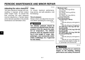
...production of craftsmanship and reliability that you an understanding of the operation, inspection, and basic maintenance of this Yamaha motorcycle fully comply with the emissions standards for clean air applicable at the date...performance or economy of operation of the Yamaha Road Star™/Road Star™ Silverado™. The design and manufacture of manufacture. This manual will give you and your motorcycle, please consult a Yamaha dealer. Yamaha has met these high standards, it is the result of your Yamaha dealer pay close attention to the recommended maintenance schedules...
...production of craftsmanship and reliability that you an understanding of the operation, inspection, and basic maintenance of this Yamaha motorcycle fully comply with the emissions standards for clean air applicable at the date...performance or economy of operation of the Yamaha Road Star™/Road Star™ Silverado™. The design and manufacture of manufacture. This manual will give you and your motorcycle, please consult a Yamaha dealer. Yamaha has met these high standards, it is the result of your Yamaha dealer pay close attention to the recommended maintenance schedules...
Owners Manual
Page 6
......2-5 INSTRUMENT AND CONTROL FUNCTIONS ...3-1 Main switch/steering lock ...3-1 Indicator and warning lights ...3-2 Speedometer unit ...3-2 Self-diagnosis device ...3-3 Fuel gauge ...3-3 Clock ...3-4 Handlebar switches ...3-4 Clutch lever ...3-5 Shift pedal ...3-6 Brake lever ...3-6 Brake pedal ...3-6 Fuel tank cap ...3-7 Fuel ...3-7 Fuel cock ...3-8 Starter (choke) knob ...3-9 Locking the steering with a padlock ...3-10 Rider seat ...3-10 Helmet holder ...3-11 Windshield [XV17AT(C)]...3-11 Saddlebags [XV17AT(C)] ...3-12 Adjusting the shock absorber assembly ...3-13 Sidestand ...3-15 Ignition...
......2-5 INSTRUMENT AND CONTROL FUNCTIONS ...3-1 Main switch/steering lock ...3-1 Indicator and warning lights ...3-2 Speedometer unit ...3-2 Self-diagnosis device ...3-3 Fuel gauge ...3-3 Clock ...3-4 Handlebar switches ...3-4 Clutch lever ...3-5 Shift pedal ...3-6 Brake lever ...3-6 Brake pedal ...3-6 Fuel tank cap ...3-7 Fuel ...3-7 Fuel cock ...3-8 Starter (choke) knob ...3-9 Locking the steering with a padlock ...3-10 Rider seat ...3-10 Helmet holder ...3-11 Windshield [XV17AT(C)]...3-11 Saddlebags [XV17AT(C)] ...3-12 Adjusting the shock absorber assembly ...3-13 Sidestand ...3-15 Ignition...

Owners Manual
Page 7
... the steering ...6-29 Checking the wheel bearings ...6-30 Battery ...6-30 Replacing the fuses ...6-32 Replacing the headlight bulb ...6-33 Tail/brake light ...6-34 Replacing a turn signal light bulb ...6-34 Replacing a license plate light bulb ...6-35 Supporting the motorcycle ...6-35 Troubleshooting ...6-36 Troubleshooting chart ...6-37 MOTORCYCLE CARE AND STORAGE ...7-1 Care ...7-1 Storage ...7-4 SPECIFICATIONS ...8-1 CONSUMER INFORMATION...9-1 Identification numbers ...9-1 Reporting safety defects ...9-3 Motorcycle noise regulation ...9-4 Maintenance record ...9-5 YAMAHA MOTOR CORPORATION...
... the steering ...6-29 Checking the wheel bearings ...6-30 Battery ...6-30 Replacing the fuses ...6-32 Replacing the headlight bulb ...6-33 Tail/brake light ...6-34 Replacing a turn signal light bulb ...6-34 Replacing a license plate light bulb ...6-35 Supporting the motorcycle ...6-35 Troubleshooting ...6-36 Troubleshooting chart ...6-37 MOTORCYCLE CARE AND STORAGE ...7-1 Care ...7-1 Storage ...7-4 SPECIFICATIONS ...8-1 CONSUMER INFORMATION...9-1 Identification numbers ...9-1 Reporting safety defects ...9-3 Motorcycle noise regulation ...9-4 Maintenance record ...9-5 YAMAHA MOTOR CORPORATION...

Owners Manual
Page 9
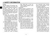
... the control levers, footrests, or wheels and cause injury or an accident. Always wear protective clothing that other drugs. Never ride under the influence of the motorcycle. • The passenger should also observe the precautions mentioned above. 1 Modifications Modifications made to this motorcycle not approved by road and traffic conditions. • Always signal before turning or changing lanes...
... the control levers, footrests, or wheels and cause injury or an accident. Always wear protective clothing that other drugs. Never ride under the influence of the motorcycle. • The passenger should also observe the precautions mentioned above. 1 Modifications Modifications made to this motorcycle not approved by road and traffic conditions. • Always signal before turning or changing lanes...
Owners Manual
Page 10
... cross winds. G Shifting weights can displace the operator from his or her normal riding position. G Never attach any accessories. Keep the following in any way reduce ground clearance or cornering clearance, limit suspension travel, steering travel or control operation, or obscure lights or reflectors. • Accessories fitted to the motorcycle as possible. If accessories are securely attached to lift the motorcycle...
... cross winds. G Shifting weights can displace the operator from his or her normal riding position. G Never attach any accessories. Keep the following in any way reduce ground clearance or cornering clearance, limit suspension travel, steering travel or control operation, or obscure lights or reflectors. • Accessories fitted to the motorcycle as possible. If accessories are securely attached to lift the motorcycle...
Owners Manual
Page 11
... adding electrical accessories. G Never start the engine or let it run for manual type). When parking the motorcycle, note the following: • The engine and exhaust system may leak out of gasoline vapor, or allow gasoline to get into your 1-4 eyes, see your clothes. 1 G G Always turn the engine off before leaving the motorcycle unattended and remove the key from the main switch. The exhaust fumes...
... adding electrical accessories. G Never start the engine or let it run for manual type). When parking the motorcycle, note the following: • The engine and exhaust system may leak out of gasoline vapor, or allow gasoline to get into your 1-4 eyes, see your clothes. 1 G G Always turn the engine off before leaving the motorcycle unattended and remove the key from the main switch. The exhaust fumes...

Owners Manual
Page 20
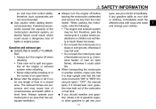
... 1. INSTRUMENT AND CONTROL FUNCTIONS EAU10460 EAU10680 Main switch/steering lock LOCK The steering is locked, and all the way to the left. 2. The key cannot be switched off . WARNING Never turn the key to "OFF" or "LOCK" while the vehicle is used to "OFF" or "LOCK". 1. EAU10520 Push the key in from the "OFF" position, and then turn it to "LOCK" while still pushing it . The main switch/steering lock controls the ignition and lighting...
... 1. INSTRUMENT AND CONTROL FUNCTIONS EAU10460 EAU10680 Main switch/steering lock LOCK The steering is locked, and all the way to the left. 2. The key cannot be switched off . WARNING Never turn the key to "OFF" or "LOCK" while the vehicle is used to "OFF" or "LOCK". 1. EAU10520 Push the key in from the "OFF" position, and then turn it to "LOCK" while still pushing it . The main switch/steering lock controls the ignition and lighting...

Owners Manual
Page 21
... electrical circuit of the headlight is switched on. EAU11060 Neutral indicator light " " This indicator light comes on when the transmission is pushed to the left ) switches the display between the odometer mode "ODO" and the tripmeter modes "TRIP A" and "TRIP B" in the neutral position. Odometer/tripmeter/clock Speedometer Fuel gauge Set button Mode button The speedometer unit is defective. " EAU11500 3 " EAU11020 Turn signal...
... electrical circuit of the headlight is switched on. EAU11060 Neutral indicator light " " This indicator light comes on when the transmission is pushed to the left ) switches the display between the odometer mode "ODO" and the tripmeter modes "TRIP A" and "TRIP B" in the neutral position. Odometer/tripmeter/clock Speedometer Fuel gauge Set button Mode button The speedometer unit is defective. " EAU11500 3 " EAU11020 Turn signal...
Owners Manual
Page 24
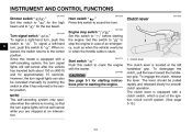
... the clutch, release the lever. The clutch lever is equipped with a clutch switch, which is stuck. EAU12710 Start switch " " Push this switch to " " before starting instructions prior to " ". Since this model is located at an intersection. The clutch lever is equipped with the starter. Engine stop the engine in after the vehicle has traveled both about 150 m (490 ft) and for approximately 15 seconds. INSTRUMENT AND CONTROL...
... the clutch, release the lever. The clutch lever is equipped with a clutch switch, which is stuck. EAU12710 Start switch " " Push this switch to " " before starting instructions prior to " ". Since this model is located at an intersection. The clutch lever is equipped with the starter. Engine stop the engine in after the vehicle has traveled both about 150 m (490 ft) and for approximately 15 seconds. INSTRUMENT AND CONTROL...
Owners Manual
Page 27
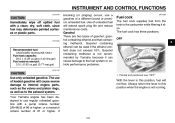
... when the engine is not recommended by Yamaha because it also. Use of unleaded fuel will not flow. Your Yamaha engine has been designed to this position, fuel will extend spark plug life and reduce maintenance costs. Always return the lever to use a gasoline of a different brand or premium unleaded fuel. INSTRUMENT AND CONTROL FUNCTIONS ECA10070 CAUTION: Immediately wipe off spilled fuel with a pump octane...
... when the engine is not recommended by Yamaha because it also. Use of unleaded fuel will not flow. Your Yamaha engine has been designed to this position, fuel will extend spark plug life and reduce maintenance costs. Always return the lever to use a gasoline of a different brand or premium unleaded fuel. INSTRUMENT AND CONTROL FUNCTIONS ECA10070 CAUTION: Immediately wipe off spilled fuel with a pump octane...
Owners Manual
Page 34
... system before starting off system (comprising the sidestand switch, clutch switch and neutral switch) has the following procedure. Periodically check the operation of the ignition circuit cut -off system according to assist the operator in gear and the sidestand is moved down . EWA10250 3 WARNING The vehicle must not be ridden with your foot while holding the vehicle upright. INSTRUMENT AND CONTROL FUNCTIONS EAU15300...
... system before starting off system (comprising the sidestand switch, clutch switch and neutral switch) has the following procedure. Periodically check the operation of the ignition circuit cut -off system according to assist the operator in gear and the sidestand is moved down . EWA10250 3 WARNING The vehicle must not be ridden with your foot while holding the vehicle upright. INSTRUMENT AND CONTROL FUNCTIONS EAU15300...
Owners Manual
Page 39
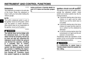
... area for the ignition circuit cut -off after a few seconds, and then try again. Start the engine by pushing the start switch, wait a few seconds. Shift the transmission into the neutral position. CAUTION: The engine trouble warning light should be met: G The transmission is not raised completely, it in the neutral position. ECA11370 WARNING G G Before starting the engine, check the function of time. Turn the fuel cock lever to...
... area for the ignition circuit cut -off after a few seconds, and then try again. Start the engine by pushing the start switch, wait a few seconds. Shift the transmission into the neutral position. CAUTION: The engine trouble warning light should be met: G The transmission is not raised completely, it in the neutral position. ECA11370 WARNING G G Before starting the engine, check the function of time. Turn the fuel cock lever to...
Owners Manual
Page 41
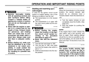
... the same procedure when shifting to slow the motorcycle. 2. Shift pedal 2. Open the throttle part way and gradually release the clutch lever. 7. Shift the transmission into first gear. Always use the brakes to stall or runs very roughly, pull the clutch lever in the neutral position, do not coast for long periods of engine power available for starting off , and do not tow the motorcycle for...
... the same procedure when shifting to slow the motorcycle. 2. Shift pedal 2. Open the throttle part way and gradually release the clutch lever. 7. Shift the transmission into first gear. Always use the brakes to stall or runs very roughly, pull the clutch lever in the neutral position, do not coast for long periods of engine power available for starting off , and do not tow the motorcycle for...
Owners Manual
Page 46
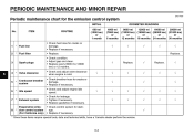
... valve clearance when engine is cold. • Check breather hose for cracks or damage. • Replace if necessary. • Check and adjust engine idle speed. • Check for leakage. • Tighten if necessary. • Replace gasket(s) if necessary. • Check control system for the emission control system INITIAL No. PERIODIC MAINTENANCE AND MINOR REPAIR EAU17600 Periodic maintenance chart for damage. • Replace if necessary. √ √ 3 Spark plugs Replace...
... valve clearance when engine is cold. • Check breather hose for cracks or damage. • Replace if necessary. • Check and adjust engine idle speed. • Check for leakage. • Tighten if necessary. • Replace gasket(s) if necessary. • Check control system for the emission control system INITIAL No. PERIODIC MAINTENANCE AND MINOR REPAIR EAU17600 Periodic maintenance chart for damage. • Replace if necessary. √ √ 3 Spark plugs Replace...

Owners Manual
Page 56
...MAINTENANCE AND MINOR REPAIR 15. Remove the oil check bolt, and then check the oil level in a false reading. 2. Place the vehicle on a level surface and hold it if necessary. Transfer case oil check hole 4. In addition, the oil must be checked before each ride. If the oil... install the oil filler cap. 1. To check the transfer case oil level 1. Transfer case oil filler cap 2. Turn the engine off, and then check the oil level and correct it in the periodic maintenance and lubrication chart. Transfer case oil level check bolt 6 1. Install the oil check bolt, and then...
...MAINTENANCE AND MINOR REPAIR 15. Remove the oil check bolt, and then check the oil level in a false reading. 2. Place the vehicle on a level surface and hold it if necessary. Transfer case oil check hole 4. In addition, the oil must be checked before each ride. If the oil... install the oil filler cap. 1. To check the transfer case oil level 1. Transfer case oil filler cap 2. Turn the engine off, and then check the oil level and correct it in the periodic maintenance and lubrication chart. Transfer case oil level check bolt 6 1. Install the oil check bolt, and then...
Owners Manual
Page 60
..., passenger, and accessories (windshield, saddlebags, etc. Tire inflation pressure must be adjusted by a Yamaha dealer at the intervals specified in improper air-fuel mixture and/or engine noise. if approved for this from occurring, the valve clearance must be checked and adjusted when the temperature of cargo, rider, passenger and accessories EWA11020 WARNING Because loading has an enormous impact on the handling, braking, performance and safety characteris- 6-17 Tires...
..., passenger, and accessories (windshield, saddlebags, etc. Tire inflation pressure must be adjusted by a Yamaha dealer at the intervals specified in improper air-fuel mixture and/or engine noise. if approved for this from occurring, the valve clearance must be checked and adjusted when the temperature of cargo, rider, passenger and accessories EWA11020 WARNING Because loading has an enormous impact on the handling, braking, performance and safety characteris- 6-17 Tires...

Owners Manual
Page 75
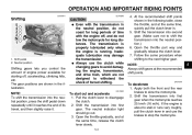
...Signaling system fuse Ignition fuse Headlight fuse Carburetor heater fuse Odometer and clock fuse (backup) Spare fuse Specified fuses: Main fuse: 30.0 A Headlight fuse: 15.0 A Signaling system fuse: 10.0 A Ignition fuse: 15.0 A Odometer and clock fuse (backup): 5.0 A Carburetor heater fuse: 10.0 A ECA10640 CAUTION: Do not use a fuse of the specified amperage. 1. 2. 3. 4. 5. 6. If the fuse immediately blows again, have a Yamaha dealer check the electrical system. 6 1. Main fuse 2. PERIODIC MAINTENANCE AND MINOR REPAIR EAU23521 Replacing the fuses 1. Bolt The main fuse and the fuse...
...Signaling system fuse Ignition fuse Headlight fuse Carburetor heater fuse Odometer and clock fuse (backup) Spare fuse Specified fuses: Main fuse: 30.0 A Headlight fuse: 15.0 A Signaling system fuse: 10.0 A Ignition fuse: 15.0 A Odometer and clock fuse (backup): 5.0 A Carburetor heater fuse: 10.0 A ECA10640 CAUTION: Do not use a fuse of the specified amperage. 1. 2. 3. 4. 5. 6. If the fuse immediately blows again, have a Yamaha dealer check the electrical system. 6 1. Main fuse 2. PERIODIC MAINTENANCE AND MINOR REPAIR EAU23521 Replacing the fuses 1. Bolt The main fuse and the fuse...
Owners Manual
Page 86
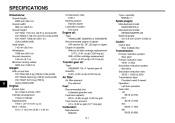
...) Ground clearance: 145 mm (5.7 in) Minimum turning radius: 3200 mm (126.0 in) Compression ratio: 8.36 :1 Starting system: Electric starter Lubrication system: Dry sump Type x quantity: BSR40 x 1 Spark plug(s): Manufacturer/model: NGK/DPR7EA-9 Manufacturer/model: DENSO/X22EPR-U9 Spark plug gap: 0.8-0.9 mm (0.031-0.035 in) Engine oil: Type: YAMALUBE 4(20W40) or SAE20W40 Recommended engine oil glade: API service SE, SF, SG type or higher Engine oil quantity: Without oil filter cartridge replacement...
...) Ground clearance: 145 mm (5.7 in) Minimum turning radius: 3200 mm (126.0 in) Compression ratio: 8.36 :1 Starting system: Electric starter Lubrication system: Dry sump Type x quantity: BSR40 x 1 Spark plug(s): Manufacturer/model: NGK/DPR7EA-9 Manufacturer/model: DENSO/X22EPR-U9 Spark plug gap: 0.8-0.9 mm (0.031-0.035 in) Engine oil: Type: YAMALUBE 4(20W40) or SAE20W40 Recommended engine oil glade: API service SE, SF, SG type or higher Engine oil quantity: Without oil filter cartridge replacement...

Owners Manual
Page 88
SPECIFICATIONS Headlight: Bulb type: Halogen bulb Carburetor heater fuse: 10.0 A Odometer and clock fuse (backup): 5.0 A Bulb voltage, wattage x quantity: Headlight: 12 V, 60.0 W/55.0 W × 1 Tail/brake light: LED Front turn signal/position light: 12 V-23.0 W/8.0 W × 2 Rear turn signal light: 12 V, 21.0 W × 2 Licence plate light: 12 V, 5.0 W × 1 Meter lighting: 14 V, 0.56 W x 4 Neutral indicator light: 14 V, 1.12 W High beam indicator light: 14 V, 1.12 W Turn signal indicator light: 14 V, 1.12 W Fuel level warning light: LEDx1 8 Fuses: Main fuse: 30.0 A Headlight fuse: 15...
SPECIFICATIONS Headlight: Bulb type: Halogen bulb Carburetor heater fuse: 10.0 A Odometer and clock fuse (backup): 5.0 A Bulb voltage, wattage x quantity: Headlight: 12 V, 60.0 W/55.0 W × 1 Tail/brake light: LED Front turn signal/position light: 12 V-23.0 W/8.0 W × 2 Rear turn signal light: 12 V, 21.0 W × 2 Licence plate light: 12 V, 5.0 W × 1 Meter lighting: 14 V, 0.56 W x 4 Neutral indicator light: 14 V, 1.12 W High beam indicator light: 14 V, 1.12 W Turn signal indicator light: 14 V, 1.12 W Fuel level warning light: LEDx1 8 Fuses: Main fuse: 30.0 A Headlight fuse: 15...

Owners Manual
Page 99
... ...6-3 Maintenance, periodic ...6-1 Maintenance record ...9-5 Model label...9-2 D Dimmer switch ...3-5 Drive belt slack ...6-25 E Engine break-in ...5-4 Engine oil and oil filter cartridge ...6-10 Engine, starting a warm...5-2 Engine stop switch...3-5 Engine trouble warning light ...3-2 T Tail/brake light ...6-34 Throttle cable free play, adjusting...6-16 Throttle grip and cable, checking and lubricating ...6-27 Tires...6-17 Tool kit ...6-1 Transfer case oil ...6-13 N Neutral indicator light ...3-2 Noise regulation ...9-4 F Front and rear brake pads, checking...6-23 P Panel, removing...
... ...6-3 Maintenance, periodic ...6-1 Maintenance record ...9-5 Model label...9-2 D Dimmer switch ...3-5 Drive belt slack ...6-25 E Engine break-in ...5-4 Engine oil and oil filter cartridge ...6-10 Engine, starting a warm...5-2 Engine stop switch...3-5 Engine trouble warning light ...3-2 T Tail/brake light ...6-34 Throttle cable free play, adjusting...6-16 Throttle grip and cable, checking and lubricating ...6-27 Tires...6-17 Tool kit ...6-1 Transfer case oil ...6-13 N Neutral indicator light ...3-2 Noise regulation ...9-4 F Front and rear brake pads, checking...6-23 P Panel, removing...