
User Manual
Page 3
... SFP Transceivers 18 Inserting an SFP Transceiver 18 Removing an SFP Transceiver 19 Performing Spot Checks 19 3 CONNECTING TO THE WEB INTERFACE Requirements for Accessing the Web Interface 21 Running the Discovery Application 21 Logging On to the Web Interface 22 Navigating Around the Web Interface 23 Menu 23 Buttons 24 Device Mimic 24 Accessing the Interface Without Using Discovery 25 DHCP Assigned IP Address 25 Manually Assigned (Static) IP Address 25 4 CONFIGURING THE SWITCH Configuration Overview 27 Viewing Switch...
... SFP Transceivers 18 Inserting an SFP Transceiver 18 Removing an SFP Transceiver 19 Performing Spot Checks 19 3 CONNECTING TO THE WEB INTERFACE Requirements for Accessing the Web Interface 21 Running the Discovery Application 21 Logging On to the Web Interface 22 Navigating Around the Web Interface 23 Menu 23 Buttons 24 Device Mimic 24 Accessing the Interface Without Using Discovery 25 DHCP Assigned IP Address 25 Manually Assigned (Static) IP Address 25 4 CONFIGURING THE SWITCH Configuration Overview 27 Viewing Switch...

User Manual
Page 4
... Configuring Link Aggregation 37 Guidelines for Creating Aggregated Links 38 Defining the Members of an Aggregated Link 38 Modifying Settings and Deleting an Aggregated Link 39 Viewing the Trunk Summary 39 Viewing Statistics 40 Mirroring Port Traffic 41 Running Cable Diagnostic 42 Using the System Tools 42 Restart 42 Configuration 43 Resetting to Factory Defaults 43 Backing Up and Restoring Configuration 44 Upgrade 44 Spanning Tree 45 802.1p Prioritization 46 Viewing Support Information 47 5 TROUBLESHOOTING Forgotten Password 49 Forgotten Static IP Address 49 Solving LED...
... Configuring Link Aggregation 37 Guidelines for Creating Aggregated Links 38 Defining the Members of an Aggregated Link 38 Modifying Settings and Deleting an Aggregated Link 39 Viewing the Trunk Summary 39 Viewing Statistics 40 Mirroring Port Traffic 41 Running Cable Diagnostic 42 Using the System Tools 42 Restart 42 Configuration 43 Resetting to Factory Defaults 43 Backing Up and Restoring Configuration 44 Upgrade 44 Spanning Tree 45 802.1p Prioritization 46 Viewing Support Information 47 5 TROUBLESHOOTING Forgotten Password 49 Forgotten Static IP Address 49 Solving LED...
User Manual
Page 7
... medium dependent interface (MDI) and medium dependent interface crossover (MDIX) connections. SFP Ports The four SFP ports support fiber Gigabit Ethernet short-wave (SX) and long-wave (LX) SFP transceivers in full duplex mode. No configuration is ideal for users who want the high-speed performance of 10/100/1000 switching with the added functionality of MDI/MDIX Connections All ports on the front panel for use configurable Switch. Autosensing of Gigabit links, but do...
... medium dependent interface (MDI) and medium dependent interface crossover (MDIX) connections. SFP Ports The four SFP ports support fiber Gigabit Ethernet short-wave (SX) and long-wave (LX) SFP transceivers in full duplex mode. No configuration is ideal for users who want the high-speed performance of 10/100/1000 switching with the added functionality of MDI/MDIX Connections All ports on the front panel for use configurable Switch. Autosensing of Gigabit links, but do...

User Manual
Page 16
... ON/OFF switch. To power on the Switch: 1 Plug the power cord into a power outlet. If the Power LED does not light up, refer to "(6) Power LED" on self-test (POST). Table 5 Possible Power LED Colors After POST Color State Green The unit is clean and free from lightning and power surges. If the Power LED turns yellow after POST. Ensure that POST failed and the Switch has entered fail-safe mode. Refer to "(8) Power Supply" on...
... ON/OFF switch. To power on the Switch: 1 Plug the power cord into a power outlet. If the Power LED does not light up, refer to "(6) Power LED" on self-test (POST). Table 5 Possible Power LED Colors After POST Color State Green The unit is clean and free from lightning and power surges. If the Power LED turns yellow after POST. Ensure that POST failed and the Switch has entered fail-safe mode. Refer to "(8) Power Supply" on...
User Manual
Page 17
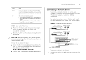
... Mbps link Endstations on . Check the Power LED and see if POST was powered on switched 100 Mbps or 1000 Mbps connections To connect a device to the Switch: 1 Connect one end of the cable to reconfigure the Switch after you reset it on the Switch. If these do not resolve the issue: ■ Check the 3Com Knowledgebase for 10 Mbps connections). See "Resetting to its factory defaults erases all your 3Com network...
... Mbps link Endstations on . Check the Power LED and see if POST was powered on switched 100 Mbps or 1000 Mbps connections To connect a device to the Switch: 1 Connect one end of the cable to reconfigure the Switch after you reset it on the Switch. If these do not resolve the issue: ■ Check the 3Com Knowledgebase for 10 Mbps connections). See "Resetting to its factory defaults erases all your 3Com network...
User Manual
Page 24
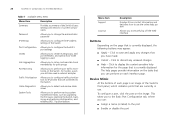
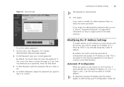
... save and apply any unsaved changes ■ Help - 24 CHAPTER 3: CONNECTING TO THE WEB INTERFACE Table 7 Available Menu Items Menu Item Description Summary Provides a summary of the Switch's basic settings and versions of current components Password Allows you to change the administrator password IP Settings Allows you to configure the IP address settings of the Switch's front panel, which indicates ports that is currently displayed. Click to perform port traffic monitoring...
... save and apply any unsaved changes ■ Help - 24 CHAPTER 3: CONNECTING TO THE WEB INTERFACE Table 7 Available Menu Items Menu Item Description Summary Provides a summary of the Switch's basic settings and versions of current components Password Allows you to change the administrator password IP Settings Allows you to configure the IP address settings of the Switch's front panel, which indicates ports that is currently displayed. Click to perform port traffic monitoring...
User Manual
Page 25
... assigned the Switch the IP address 192.168.0.123, start your Web browser, and then type http://192.168.0.123. This sticker contains the MAC address and default IP address of the Switch. ■ Enable or disable flow control ■ Configure the speed duplex settings ■ Set traffic priority for the IP address that is assigned to the Switch, and then using Discovery. Accessing the Interface Without Using Discovery 25 For example, if the DHCP server assigned the...
... assigned the Switch the IP address 192.168.0.123, start your Web browser, and then type http://192.168.0.123. This sticker contains the MAC address and default IP address of the Switch. ■ Enable or disable flow control ■ Configure the speed duplex settings ■ Set traffic priority for the IP address that is assigned to the Switch, and then using Discovery. Accessing the Interface Without Using Discovery 25 For example, if the DHCP server assigned the...

User Manual
Page 27
...; Changing the Admin Password ■ Modifying the IP Address Settings ■ Configuring Port Settings ■ Configuring VLANs ■ Configuring Link Aggregation ■ Viewing Statistics ■ Mirroring Port Traffic ■ Running Cable Diagnostic ■ Using the System Tools ■ Viewing Support Information Configuration Overview The Switch is shipped ready for use. If you only want to: ■ Set the administration password to the Web interface ■ Assign an IP address to the Switch ■ Configure the Switch's advanced features ■ Upgrade the firmware Viewing...
...; Changing the Admin Password ■ Modifying the IP Address Settings ■ Configuring Port Settings ■ Configuring VLANs ■ Configuring Link Aggregation ■ Viewing Statistics ■ Mirroring Port Traffic ■ Running Cable Diagnostic ■ Using the System Tools ■ Viewing Support Information Configuration Overview The Switch is shipped ready for use. If you only want to: ■ Set the administration password to the Web interface ■ Assign an IP address to the Switch ■ Configure the Switch's advanced features ■ Upgrade the firmware Viewing...

User Manual
Page 28
... switch, 3Com recommends that you request for technical assistance from accessing the Web interface and modifying the Switch's settings, the interface is password-protected. It also shows the object ID and the time elapsed since the Switch was last started. If you can view on the Switch ■ Management Software Information - Shows the IP address settings of the loader (firmware), boot ROM, and code. Shows the serial number, total number of ports, and the version...
... switch, 3Com recommends that you request for technical assistance from accessing the Web interface and modifying the Switch's settings, the interface is password-protected. It also shows the object ID and the time elapsed since the Switch was last started. If you can view on the Switch ■ Management Software Information - Shows the IP address settings of the loader (firmware), boot ROM, and code. Shows the serial number, total number of ports, and the version...
User Manual
Page 29
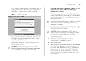
..., refer to "Forgotten Password" on page 48 for information on how to regain access to the Web interface. Modifying the IP Address Settings 29 The password is necessary for the first time, it automatically uses the default IP address 169.254.x.y, where x and y are the last two bytes of its MAC address. If this field blank. 3 In New Password, type the password that the Switch assigns to the Web interface...
..., refer to "Forgotten Password" on page 48 for information on how to regain access to the Web interface. Modifying the IP Address Settings 29 The password is necessary for the first time, it automatically uses the default IP address 169.254.x.y, where x and y are the last two bytes of its MAC address. If this field blank. 3 In New Password, type the password that the Switch assigns to the Web interface...
User Manual
Page 30
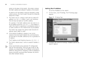
... a standalone mode, or no other network devices. Available options are converted from the last two bytes of the Switch. Setting the IP Address To set the IP address for the initial setup. This sticker contains the MAC address and default IP address of the MAC address by using DHCP or assigning a static IP address) to configure itself . 2 If this default IP address is found. 3Com recommends using the automatic configuration process, the Switch goes through...
... a standalone mode, or no other network devices. Available options are converted from the last two bytes of the Switch. Setting the IP Address To set the IP address for the initial setup. This sticker contains the MAC address and default IP address of the MAC address by using DHCP or assigning a static IP address) to configure itself . 2 If this default IP address is found. 3Com recommends using the automatic configuration process, the Switch goes through...

User Manual
Page 31
... Static. IP Address Mode Specify how the Switch will only be accessed. This option is only available if IP Address Mode is 255.255.0.0. Configuring Port Settings Using the Web interface, you want the Switch to the Switch. Physical port number Select this option if you have a DHCP server on other VLANs, you configure the Switch's IP address settings, click Apply to VLAN 1. Select this Switch and management stations on the network and you can also view the current connection status...
... Static. IP Address Mode Specify how the Switch will only be accessed. This option is only available if IP Address Mode is 255.255.0.0. Configuring Port Settings Using the Web interface, you want the Switch to the Switch. Physical port number Select this option if you have a DHCP server on other VLANs, you configure the Switch's IP address settings, click Apply to VLAN 1. Select this Switch and management stations on the network and you can also view the current connection status...

User Manual
Page 34
... VLAN at any group of ports into separate broadcast domains. Setting a port as an uplink (tagged) VLAN port forwards all VLAN traffic from all the VLANs on this Switch to external devices, you will no physical barriers, and allows users to VLANs other than VLAN 1, you must always be set to the backbone of the network. If this port. By default, all ports belong to organize any time. 34 CHAPTER 4: CONFIGURING THE SWITCH VLAN...
... VLAN at any group of ports into separate broadcast domains. Setting a port as an uplink (tagged) VLAN port forwards all VLAN traffic from all the VLANs on this Switch to external devices, you will no physical barriers, and allows users to VLANs other than VLAN 1, you must always be set to the backbone of the network. If this port. By default, all ports belong to organize any time. 34 CHAPTER 4: CONFIGURING THE SWITCH VLAN...

User Manual
Page 35
... include: ■ N - Uplink egress packets ■ D - Sample VLAN Configurations To illustrate how you can segment network devices that you will need to reset the Switch to "Sample VLAN Configurations" on the Switch using desktop connections. 4 Define the VLAN membership by setting the state of each port. For examples on setting up a simple VLAN on page 35. To change states, click the icon under the port number repeatedly to create the VLAN. VLAN IDs range...
... include: ■ N - Uplink egress packets ■ D - Sample VLAN Configurations To illustrate how you can segment network devices that you will need to reset the Switch to "Sample VLAN Configurations" on the Switch using desktop connections. 4 Define the VLAN membership by setting the state of each port. For examples on setting up a simple VLAN on page 35. To change states, click the icon under the port number repeatedly to create the VLAN. VLAN IDs range...

User Manual
Page 36
... shown in VLAN 2 Baseline Switch 2824-SFP Plus add another port to the VLAN or change the port configuration. This enables ports that a port on VLAN2 cannot communicate with any other , do the following: 1 Create a new VLAN and set the VLAN ID to 2. Ports 7, 8, and 16 now belong to VLAN2, and will not be able communicate with each Switch is the default VLAN and already exists. 2 Set ports 7, 8, and 16 to D (desktop egress packet). 3 Click...
... shown in VLAN 2 Baseline Switch 2824-SFP Plus add another port to the VLAN or change the port configuration. This enables ports that a port on VLAN2 cannot communicate with any other , do the following: 1 Create a new VLAN and set the VLAN ID to 2. Ports 7, 8, and 16 now belong to VLAN2, and will not be able communicate with each Switch is the default VLAN and already exists. 2 Set ports 7, 8, and 16 to D (desktop egress packet). 3 Click...

User Manual
Page 37
... uplink port on Switch 2 (in this example, port 8). Click Apply. 4 Connect the uplink port on Switch 1 (in this example, port 16) to U (uplink egress packet). You need not create VLAN1 since it . Those ports on Switch 1 that are members of VLAN2 to U (uplink egress packet). Configuring Link Aggregation Ports can now communicate with those ports on Switch 2 that you deleted disappears from the VLAN ID list. This increases the bandwidth of VLAN2 to it exists by default. Removing a VLAN To remove...
... uplink port on Switch 2 (in this example, port 8). Click Apply. 4 Connect the uplink port on Switch 1 (in this example, port 16) to U (uplink egress packet). You need not create VLAN1 since it . Those ports on Switch 1 that are members of VLAN2 to U (uplink egress packet). Configuring Link Aggregation Ports can now communicate with those ports on Switch 2 that you deleted disappears from the VLAN ID list. This increases the bandwidth of VLAN2 to it exists by default. Removing a VLAN To remove...

User Manual
Page 46
... multiple traffic queues that are shown in the hardware of the spanning tree network, set to "Block and Discard." 802.1p Prioritization The Switch has priority queuing enabled, which relates to forward or block spanning tree BPDUs. Spanning tree BPDUs received on a different queue from lower priority traffic, and is connected only to 7), each of service. The Switch does not forward BPDUs to comply with 802.1p, VLAN tagged frames. If a packet...
... multiple traffic queues that are shown in the hardware of the spanning tree network, set to "Block and Discard." 802.1p Prioritization The Switch has priority queuing enabled, which relates to forward or block spanning tree BPDUs. Spanning tree BPDUs received on a different queue from lower priority traffic, and is connected only to 7), each of service. The Switch does not forward BPDUs to comply with 802.1p, VLAN tagged frames. If a packet...

User Manual
Page 49
... the static IP address that : admin ■ Password - See "Resetting to Factory Defaults" on basic LED checks, refer to the following topics in Chapter 1: ■ (3) Link/Activity Status LEDs ■ (4) Module Active LEDs ■ (5) Port Duplex LEDs ■ (6) Power LED A link is connected but the Link/Activity Status LED for the port does not light There is not listed here and you cannot solve it , you may encounter while installing, using, and managing the Switch, with this connection. After resetting the Switch, log on to the Web interface using...
... the static IP address that : admin ■ Password - See "Resetting to Factory Defaults" on basic LED checks, refer to the following topics in Chapter 1: ■ (3) Link/Activity Status LEDs ■ (4) Module Active LEDs ■ (5) Port Duplex LEDs ■ (6) Power LED A link is connected but the Link/Activity Status LED for the port does not light There is not listed here and you cannot solve it , you may encounter while installing, using, and managing the Switch, with this connection. After resetting the Switch, log on to the Web interface using...
User Manual
Page 51
... the LED flashes, release the recovery button. The Switch will now enter fail safe mode, whereby the Switch's IP address, user name and password will cause the current configuration to be reset to upgrade the firmware. If the firmware image becomes corrupted, you can be lost . The Discovery application can restore the default settings, using the recovery button on the Switch. CAUTION: Before recovering the Switch, save the Switch's current configuration. Otherwise, you need to the factory defaults. Recovering the Switch...
... the LED flashes, release the recovery button. The Switch will now enter fail safe mode, whereby the Switch's IP address, user name and password will cause the current configuration to be reset to upgrade the firmware. If the firmware image becomes corrupted, you can be lost . The Discovery application can restore the default settings, using the recovery button on the Switch. CAUTION: Before recovering the Switch, save the Switch's current configuration. Otherwise, you need to the factory defaults. Recovering the Switch...
User Manual
Page 54
... the list below. First time users will need to you must first register your product on the 3Com Web site at http://eSupport.3com.com/. Find a current directory of the package, will need to technical support and repair services. A link to software downloads can obtain an RMA number online at the time of system hardware and software, including revision level ■ Diagnostic error messages ■ Details about recent configuration changes...
... the list below. First time users will need to you must first register your product on the 3Com Web site at http://eSupport.3com.com/. Find a current directory of the package, will need to technical support and repair services. A link to software downloads can obtain an RMA number online at the time of system hardware and software, including revision level ■ Diagnostic error messages ■ Details about recent configuration changes...


