

User Guide
Page 3
... 18 Removing an SFP Transceiver 19 Performing Spot Checks 19 3 CONNECTING TO THE WEB INTERFACE Requirements for Accessing the Web Interface 21 Running the Discovery Application 21 Logging On to the Web Interface 22 Navigating the Web Interface 23 Menu 23 Buttons 24 Port Status 24 Accessing the Interface Without Using Discovery 24 DHCP Assigned IP Address 25 Manually Assigned (Static) IP Address 25 4 CONFIGURING THE SWITCH Configuration Overview 27 Viewing Summary Information 27 Changing the Admin Password 28 Modifying the IP Address Settings...
... 18 Removing an SFP Transceiver 19 Performing Spot Checks 19 3 CONNECTING TO THE WEB INTERFACE Requirements for Accessing the Web Interface 21 Running the Discovery Application 21 Logging On to the Web Interface 22 Navigating the Web Interface 23 Menu 23 Buttons 24 Port Status 24 Accessing the Interface Without Using Discovery 24 DHCP Assigned IP Address 25 Manually Assigned (Static) IP Address 25 4 CONFIGURING THE SWITCH Configuration Overview 27 Viewing Summary Information 27 Changing the Admin Password 28 Modifying the IP Address Settings...
User Guide
Page 4
... Port Settings 32 Configuring VLANs 32 Creating a VLAN 33 Deleting VLANs 33 Modifying VLANs 34 Defining VLAN Membership 34 Sample VLAN Configurations 34 Configuring Trunking 36 Guidelines for Creating Trunks 36 Creating, Modifying, and Deleting Trunks 37 Defining Trunk Membership 37 Viewing Trunk Information 37 Monitoring Traffic 38 Using the System Tools 39 Restarting the Switch 39 Resetting and Backing Up/Restoring Configuration 39 Upgrading the System Software 40 Configuring the Spanning Tree 41 802.1p Prioritization 41 5 TROUBLESHOOTING Resetting to Factory Defaults 43 Forgotten Password...
... Port Settings 32 Configuring VLANs 32 Creating a VLAN 33 Deleting VLANs 33 Modifying VLANs 34 Defining VLAN Membership 34 Sample VLAN Configurations 34 Configuring Trunking 36 Guidelines for Creating Trunks 36 Creating, Modifying, and Deleting Trunks 37 Defining Trunk Membership 37 Viewing Trunk Information 37 Monitoring Traffic 38 Using the System Tools 39 Restarting the Switch 39 Resetting and Backing Up/Restoring Configuration 39 Upgrading the System Software 40 Configuring the Spanning Tree 41 802.1p Prioritization 41 5 TROUBLESHOOTING Resetting to Factory Defaults 43 Forgotten Password...
User Guide
Page 6
... this document to 3Com at this guide, each 3Com Baseline Switch 2250 Plus documentation set includes the following information when contacting us . Accessible from the Web interface, provides information that we can only respond to comments and questions about 3Com product documentation at : pddtechpubs_comments@3com.com Please include the following : ■ Online Help - Questions related to technical support or sales should be directed in the first instance to your network...
... this document to 3Com at this guide, each 3Com Baseline Switch 2250 Plus documentation set includes the following information when contacting us . Accessible from the Web interface, provides information that we can only respond to comments and questions about 3Com product documentation at : pddtechpubs_comments@3com.com Please include the following : ■ Online Help - Questions related to technical support or sales should be directed in the first instance to your network...

User Guide
Page 7
.../MDIX Connections All ports on the Switch can therefore be operational at any given time. Autosensing of the device. Autonegotiating 10/100 Mbps Ports Each 10/100 Mbps port automatically determines the speed and duplex mode of the 3Com® Baseline Switch 2250 Plus. The 10/100 Mbps connections on the front panel. Overview of two can be used to connect to configure advanced features such as VLAN support and link aggregation...
.../MDIX Connections All ports on the Switch can therefore be operational at any given time. Autosensing of the device. Autonegotiating 10/100 Mbps Ports Each 10/100 Mbps port automatically determines the speed and duplex mode of the 3Com® Baseline Switch 2250 Plus. The 10/100 Mbps connections on the front panel. Overview of two can be used to connect to configure advanced features such as VLAN support and link aggregation...

User Guide
Page 8
... which means all packets that support the spanning tree protocol communicate with each other using SFP transceivers to detect avail- Traffic prioritization uses the multiple traffic queues that implements a spanning tree protocol topology, switches communicate with 802.1p, VLAN tagged frames. This feature is useful during excessive loads when one type of the Switch to another . The Switch is disabled. This ensures that traffic. This offers you can configure 3Com Baseline Switch 2250 Plus to forward or to...
... which means all packets that support the spanning tree protocol communicate with each other using SFP transceivers to detect avail- Traffic prioritization uses the multiple traffic queues that implements a spanning tree protocol topology, switches communicate with 802.1p, VLAN tagged frames. This feature is useful during excessive loads when one type of the Switch to another . The Switch is disabled. This ensures that traffic. This offers you can configure 3Com Baseline Switch 2250 Plus to forward or to...
User Guide
Page 17
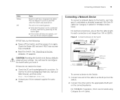
... your 3Com network supplier for a solution. See "Resetting to Factory Defaults" on the connecting device. If these do not resolve the issue: ■ Check the 3Com Knowledgebase for assistance. Figure 3 Connecting Devices to the Switch Baseline 10/100 switch Endstations on switched 100 Mbps connections Baseline 10/100 switch Endstations on switched 100 Mbps connections Baseline Switch 2250 Plus 1000 Mbps link 10 or 100 Mbps link 1000 Mbps copper or fiber connection to backbone or server...
... your 3Com network supplier for a solution. See "Resetting to Factory Defaults" on the connecting device. If these do not resolve the issue: ■ Check the 3Com Knowledgebase for assistance. Figure 3 Connecting Devices to the Switch Baseline 10/100 switch Endstations on switched 100 Mbps connections Baseline 10/100 switch Endstations on switched 100 Mbps connections Baseline Switch 2250 Plus 1000 Mbps link 10 or 100 Mbps link 1000 Mbps copper or fiber connection to backbone or server...

User Guide
Page 19
... "Troubleshooting" starting on users. 3Com recommends periodically checking the items listed in Table 7. Removing an SFP Transceiver Removing an SFP transceiver does not require powering off the Switch. not click when you should slide out easily. Attach a male duplex LC connector on the network cable into the duplex LC connector on the transceiver. 6 Connect the other end of the cable to a device fitted with an appropriate Gigabit Ethernet connection. 7 Check the Module Active LEDs...
... "Troubleshooting" starting on users. 3Com recommends periodically checking the items listed in Table 7. Removing an SFP Transceiver Removing an SFP transceiver does not require powering off the Switch. not click when you should slide out easily. Attach a male duplex LC connector on the network cable into the duplex LC connector on the transceiver. 6 Connect the other end of the cable to a device fitted with an appropriate Gigabit Ethernet connection. 7 Check the Module Active LEDs...
User Guide
Page 24
...; Configure the speed duplex settings Accessing the Interface Without Using Discovery The Discovery application works by automatically detecting the IP address that is assigned to the Switch, and then using Discovery. This takes you to the Basic Port Configuration tab, where you can access the Web interface without using that is currently displayed, the following buttons may appear: ■ Apply - 24 CHAPTER 3: CONNECTING TO THE WEB INTERFACE Menu Item Port Configuration VLANs Trunking Traffic Monitoring System Tools Support Log...
...; Configure the speed duplex settings Accessing the Interface Without Using Discovery The Discovery application works by automatically detecting the IP address that is assigned to the Switch, and then using Discovery. This takes you to the Basic Port Configuration tab, where you can access the Web interface without using that is currently displayed, the following buttons may appear: ■ Apply - 24 CHAPTER 3: CONNECTING TO THE WEB INTERFACE Menu Item Port Configuration VLANs Trunking Traffic Monitoring System Tools Support Log...

User Guide
Page 25
... to configure the Switch. Manually Assigned (Static) IP Address If you assigned a static IP address to the Switch, you need to use that IP address to access the Web interface the next time you set the IP address mode to DHCP, check the DHCP server for the IP address that is assigned to the Switch, and then use that IP address to the Switch, start your Web browser, and then type http://192.168.0.123. Accessing the Interface Without Using Discovery...
... to configure the Switch. Manually Assigned (Static) IP Address If you assigned a static IP address to the Switch, you need to use that IP address to access the Web interface the next time you set the IP address mode to DHCP, check the DHCP server for the IP address that is assigned to the Switch, and then use that IP address to the Switch, start your Web browser, and then type http://192.168.0.123. Accessing the Interface Without Using Discovery...

User Guide
Page 27
...; Changing the Admin Password ■ Modifying the IP Address Settings ■ Configuring Port Settings ■ Configuring VLANs ■ Configuring Trunking ■ Monitoring Traffic ■ Using the System Tools Configuration Overview The Switch is shipped ready for use. To modify any of current components. You only need to configure the Switch's advanced features. Shows the serial number, total number of ports, and the version of these settings, click IP Settings. Shows the IP address settings of the loader (firmware), boot ROM, and code...
...; Changing the Admin Password ■ Modifying the IP Address Settings ■ Configuring Port Settings ■ Configuring VLANs ■ Configuring Trunking ■ Monitoring Traffic ■ Using the System Tools Configuration Overview The Switch is shipped ready for use. To modify any of current components. You only need to configure the Switch's advanced features. Shows the serial number, total number of ports, and the version of these settings, click IP Settings. Shows the IP address settings of the loader (firmware), boot ROM, and code...
User Guide
Page 28
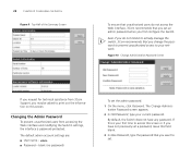
... set the admin password: 1 On the menu, click Password. Figure 10 Change Administration Password Screen If you request for technical assistance from accessing the Web interface and modifying the Switch's settings, the interface is your first time to access this screen. blank (no password) To set an admin password when you change the password to prevent unauthorized access to your network. Even if you do not access the Web interface, 3Com recommends that you first configure the Switch...
... set the admin password: 1 On the menu, click Password. Figure 10 Change Administration Password Screen If you request for technical assistance from accessing the Web interface and modifying the Switch's settings, the interface is your first time to access this screen. blank (no password) To set an admin password when you change the password to prevent unauthorized access to your network. Even if you do not access the Web interface, 3Com recommends that you first configure the Switch...

User Guide
Page 29
... connect to the Web interface. If you set it - To determine the exact IP address that the Switch assigns to itself with the Switch, you need to assign an IP address to communicate with the default IP address 169.254.x.y, where x and y are the last two bytes of its MAC address. Modifying the IP Address Settings To enable devices on the network to it , refer to "Forgotten Password...
... connect to the Web interface. If you set it - To determine the exact IP address that the Switch assigns to itself with the Switch, you need to assign an IP address to communicate with the default IP address 169.254.x.y, where x and y are the last two bytes of its MAC address. Modifying the IP Address Settings To enable devices on the network to it , refer to "Forgotten Password...

User Guide
Page 31
... not transmit more packets than a receiving device can process. When autonegotiation is enabled by default, sets the optimum combination of these settings, click Apply to 1000Mbps. When flow control is enabled by default. Enables and disables the port ■ Flow Control - Flow control is enabled, the Two tabs are available: ■ Number - Sets the speed and duplex mode of the port. Configuring Port Settings Using the Web interface, you can label it . You can also view the current connection status of high traffic.
... not transmit more packets than a receiving device can process. When autonegotiation is enabled by default, sets the optimum combination of these settings, click Apply to 1000Mbps. When flow control is enabled by default. Enables and disables the port ■ Flow Control - Flow control is enabled, the Two tabs are available: ■ Number - Sets the speed and duplex mode of the port. Configuring Port Settings Using the Web interface, you can label it . You can also view the current connection status of high traffic.
User Guide
Page 32
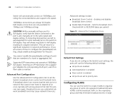
... speed. 1000Mbps connections are only available for 10Mbps and 100Mbps settings. Inserting an SFP transceiver into separate broadcast domains. This can use substantial network bandwidth and may cause network time-outs. Supported SFP transceivers only operate at 1000Mbps full-duplex. Broadcast storms use the Switch to create VLANs to organize any group of a trunk or aggregated link. Sets the broadcast storm threshold (64 to 95232000 bytes per packet) Figure 13 Advanced Port Configuration Screen Default Port Settings...
... speed. 1000Mbps connections are only available for 10Mbps and 100Mbps settings. Inserting an SFP transceiver into separate broadcast domains. This can use substantial network bandwidth and may cause network time-outs. Supported SFP transceivers only operate at 1000Mbps full-duplex. Broadcast storms use the Switch to create VLANs to organize any group of a trunk or aggregated link. Sets the broadcast storm threshold (64 to 95232000 bytes per packet) Figure 13 Advanced Port Configuration Screen Default Port Settings...

User Guide
Page 35
... VLAN2, and will not communicate with each Switch is the default VLAN and already exists. 2 Set ports 1, 3, and 26 to "Creating a VLAN" for instructions. Setting Up VLAN Across Two Switches This example explains how you can set up a VLAN across two Switches using desktop connections. Figure 18 Desktop VLAN Configuration Endstations in VLAN 2 Endstations in VLAN 1 Port 1 Port 3 BaselBinaeseSlwinietcSh w2i2tc5h0 2250 Plus Port 26 Server Server in VLAN 2 in VLAN 1 If you want to add ports 1, 3, and 26 to VLAN2 (as shown...
... VLAN2, and will not communicate with each Switch is the default VLAN and already exists. 2 Set ports 1, 3, and 26 to "Creating a VLAN" for instructions. Setting Up VLAN Across Two Switches This example explains how you can set up a VLAN across two Switches using desktop connections. Figure 18 Desktop VLAN Configuration Endstations in VLAN 2 Endstations in VLAN 1 Port 1 Port 3 BaselBinaeseSlwinietcSh w2i2tc5h0 2250 Plus Port 26 Server Server in VLAN 2 in VLAN 1 If you want to add ports 1, 3, and 26 to VLAN2 (as shown...

User Guide
Page 38
... 23 Port Traffic Monitoring Screen Only one port can be selected from the Mirror Form row, which you connected the network analyzer. To set up traffic monitoring, you need to attach a network analyzer to one port at a time. You can only monitor one port and use it to this port. itoring on the menu. The Port Traffic Monitoring Screen appears. 3 On the Monitor Port menu, select the port number that you want to a port. 2 Access the Web interface...
... 23 Port Traffic Monitoring Screen Only one port can be selected from the Mirror Form row, which you connected the network analyzer. To set up traffic monitoring, you need to attach a network analyzer to one port at a time. You can only monitor one port and use it to this port. itoring on the menu. The Port Traffic Monitoring Screen appears. 3 On the Monitor Port menu, select the port number that you want to a port. 2 Access the Web interface...
User Guide
Page 43
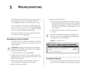
... Recovery button pressed. 3 Release the Recovery button. 4 Reset the Switch either by: ■ Accessing the Web interface using , and managing the Switch, with suggested courses of the Switch. Figure 29 Configuration Tab Forgotten Password If you forget the password to reconfigure the Switch after you reset it , check the 3Com Knowledgebase at http://knowledgebase.3com.com before contacting your local technical support representative. Click OK to regain For more information. Resetting to Factory Defaults If the Switch...
... Recovery button pressed. 3 Release the Recovery button. 4 Reset the Switch either by: ■ Accessing the Web interface using , and managing the Switch, with suggested courses of the Switch. Figure 29 Configuration Tab Forgotten Password If you forget the password to reconfigure the Switch after you reset it , check the 3Com Knowledgebase at http://knowledgebase.3com.com before contacting your local technical support representative. Click OK to regain For more information. Resetting to Factory Defaults If the Switch...

User Guide
Page 44
...; A 3Com SFP module is off . 44 CHAPTER 5: TROUBLESHOOTING access. Solving LED Issues This section lists some issues that : ■ The fiber cable is in Chapter 1: ■ (4) Module Active LEDs ■ (4) Module Active LEDs ■ (3) Link/Activity LEDs ■ (5) Power LED A link is connected, but network performance is being used. Category 3 cables can be used for 10BASE-T operation only. admin ■ Password - For information on basic LED checks, refer to the LEDs on page 21. Verify that the workstation's network interface is installed...
...; A 3Com SFP module is off . 44 CHAPTER 5: TROUBLESHOOTING access. Solving LED Issues This section lists some issues that : ■ The fiber cable is in Chapter 1: ■ (4) Module Active LEDs ■ (4) Module Active LEDs ■ (3) Link/Activity LEDs ■ (5) Power LED A link is connected, but network performance is being used. Category 3 cables can be used for 10BASE-T operation only. admin ■ Password - For information on basic LED checks, refer to the LEDs on page 21. Verify that the workstation's network interface is installed...
User Guide
Page 48
... follow the software version included with your warranty and other service benefits start from the list below. 48 APPENDIX A: OBTAINING SUPPORT FOR YOUR PRODUCT found at http://eSupport.3com.com/, or under warranty, you . First time users will be returned to technical support and repair services. When you contact 3Com for assistance, please have the following information ready: ■ Product model name, part number, and serial number ■...
... follow the software version included with your warranty and other service benefits start from the list below. 48 APPENDIX A: OBTAINING SUPPORT FOR YOUR PRODUCT found at http://eSupport.3com.com/, or under warranty, you . First time users will be returned to technical support and repair services. When you contact 3Com for assistance, please have the following information ready: ■ Product model name, part number, and serial number ■...

User Guide
Page 66
... SFP ports 8, 10 SFP transceivers 18 approved (supported) 18 inserting 18 removing 19 spot checks 19 subnet mask 62 switch defined 62 T TCP/IP 61 defined 62 traffic 63 monitoring 38 troubleshooting 43 forgotten IP address 43 forgotten password 43 LED-related issues 44 POST failed 17 trunking See link aggregation U user name default 28 V viewing status information 27 VLANs 32 creating 33, 36 maximum supported 33 sample configurations 34 W Web interface accessing directly 24 accessing using Discovery 21 buttons 24 connecting...
... SFP ports 8, 10 SFP transceivers 18 approved (supported) 18 inserting 18 removing 19 spot checks 19 subnet mask 62 switch defined 62 T TCP/IP 61 defined 62 traffic 63 monitoring 38 troubleshooting 43 forgotten IP address 43 forgotten password 43 LED-related issues 44 POST failed 17 trunking See link aggregation U user name default 28 V viewing status information 27 VLANs 32 creating 33, 36 maximum supported 33 sample configurations 34 W Web interface accessing directly 24 accessing using Discovery 21 buttons 24 connecting...


