

User Guide
Page 3
...BASELINE SWITCH Overview of the Baseline Switch 2250 Plus 7 Features and Capabilities 7 Autosensing of MDI/MDIX Connections 7 Autonegotiating 10/100 Mbps Ports 7 SFP Ports 8 Traffic Prioritization 8 Forwarding of BPDU Packets 8 Physical Features 9 Front Panel 9 Rear Panel 12 Package Contents 12 2 INSTALLING THE SWITCH Before You Begin 13 Positioning the Switch 13 Aufstellen des Switch... Kit 14 Montagesatz Anweisungen 15 Placing Units On Top of Each Other 15 Supplying Power to the Switch 16 Checking for Correct Operation 16 Connecting a Network Device 17 Using SFP Transceivers 18 Approved SFP ...
...BASELINE SWITCH Overview of the Baseline Switch 2250 Plus 7 Features and Capabilities 7 Autosensing of MDI/MDIX Connections 7 Autonegotiating 10/100 Mbps Ports 7 SFP Ports 8 Traffic Prioritization 8 Forwarding of BPDU Packets 8 Physical Features 9 Front Panel 9 Rear Panel 12 Package Contents 12 2 INSTALLING THE SWITCH Before You Begin 13 Positioning the Switch 13 Aufstellen des Switch... Kit 14 Montagesatz Anweisungen 15 Placing Units On Top of Each Other 15 Supplying Power to the Switch 16 Checking for Correct Operation 16 Connecting a Network Device 17 Using SFP Transceivers 18 Approved SFP ...
User Guide
Page 4
..., and Deleting Trunks 37 Defining Trunk Membership 37 Viewing Trunk Information 37 Monitoring Traffic 38 Using the System Tools 39 Restarting the Switch 39 Resetting and Backing Up/Restoring Configuration 39 Upgrading the System Software 40 Configuring the Spanning Tree 41 802.1p Prioritization 41 5...Register Your Product 47 Purchase Value-Added Services 47 Troubleshoot Online 47 Access Software Downloads 47 Telephone Technical Support and Repair 48 Contact Us 48 B SAFETY INFORMATION Important Safety Information 51 France and Peru Only 51 Power Cord Set 52 Consignes Importantes de Sécurit&#...
..., and Deleting Trunks 37 Defining Trunk Membership 37 Viewing Trunk Information 37 Monitoring Traffic 38 Using the System Tools 39 Restarting the Switch 39 Resetting and Backing Up/Restoring Configuration 39 Upgrading the System Software 40 Configuring the Spanning Tree 41 802.1p Prioritization 41 5...Register Your Product 47 Purchase Value-Added Services 47 Troubleshoot Online 47 Access Software Downloads 47 Telephone Technical Support and Repair 48 Contact Us 48 B SAFETY INFORMATION Important Safety Information 51 France and Peru Only 51 Power Cord Set 52 Consignes Importantes de Sécurit&#...
User Guide
Page 6
... your network supplier. Accessible from the Web interface, provides information that we can only respond to comments and questions about this document to 3Com at this guide, each 3Com Baseline Switch 2250 Plus documentation set includes the following information when contacting us . Questions related to technical support or sales should be directed in the first instance to...
... your network supplier. Accessible from the Web interface, provides information that we can only respond to comments and questions about this document to 3Com at this guide, each 3Com Baseline Switch 2250 Plus documentation set includes the following information when contacting us . Questions related to technical support or sales should be directed in the first instance to...

User Guide
Page 7
... support and link aggregation. While there are four physical Gigabit ports, only a maximum of the Baseline Switch 2250 Plus The 3Com® Baseline Switch 2250 Plus is shipped ready for use unmanaged switch. It is necessary, unless you to connect network devices to another switch port, server, or workstation without additional configuration. This allows you want the high-speed performance of...
... support and link aggregation. While there are four physical Gigabit ports, only a maximum of the Baseline Switch 2250 Plus The 3Com® Baseline Switch 2250 Plus is shipped ready for use unmanaged switch. It is necessary, unless you to connect network devices to another switch port, server, or workstation without additional configuration. This allows you want the high-speed performance of...

User Guide
Page 8
8 CHAPTER 1: INTRODUCING THE BASELINE SWITCH SFP Ports The two SFP ports support fiber Gigabit Ethernet short-wave (SX) and long-wave (LX) SFP transceivers in the following table. The Switch is implementing a spanning tree topology across multiples switches, you the flexibility of traffic. This ensures... read the priority level and determine whether the packet should be directed through the Switch without being delayed by lower priority data. This offers you can configure 3Com Baseline Switch 2250 Plus to forward or to block and discard bridge protocol data unit (BPDU) packets to ...
8 CHAPTER 1: INTRODUCING THE BASELINE SWITCH SFP Ports The two SFP ports support fiber Gigabit Ethernet short-wave (SX) and long-wave (LX) SFP transceivers in the following table. The Switch is implementing a spanning tree topology across multiples switches, you the flexibility of traffic. This ensures... read the priority level and determine whether the packet should be directed through the Switch without being delayed by lower priority data. This offers you can configure 3Com Baseline Switch 2250 Plus to forward or to block and discard bridge protocol data unit (BPDU) packets to ...

User Guide
Page 9
... Figure 1 Front and Rear Panels 1 45 6 23 7 8 Front Panel The front panel of the Switch contains a series of indicator lights (LEDs) that help describe the state of the Switch. Only connect RJ-45 data connectors, network telephony systems, or network telephones to determine the best available path...sockets, or to connect the unit to numbered sections in this diagram refer to a traditional PBX or public telephone network. able communication paths between switches and to these data sockets. The numbers in "Front Panel" on page 9 and "Rear Panel" on page 41. WARNHINWEIS: RJ-45-...
... Figure 1 Front and Rear Panels 1 45 6 23 7 8 Front Panel The front panel of the Switch contains a series of indicator lights (LEDs) that help describe the state of the Switch. Only connect RJ-45 data connectors, network telephony systems, or network telephones to determine the best available path...sockets, or to connect the unit to numbered sections in this diagram refer to a traditional PBX or public telephone network. able communication paths between switches and to these data sockets. The numbers in "Front Panel" on page 9 and "Rear Panel" on page 41. WARNHINWEIS: RJ-45-...

User Guide
Page 10
...(SFP) transceiver slots. In such a configuration, you may notice some degradation of network performance. 3Com recommends that you ensure that autonegotiation is a configurable option). (see "Troubleshooting" on the Switch. SFP ports are numbered 49 and 50 on page 43). (2) 10/100/1000BASE-T/SFP Ports ...Ports 49 and 50 are automatically determined by the capabilities of the same number. 10 CHAPTER 1: INTRODUCING THE BASELINE SWITCH Entweder geschützte oder ungesch...
...(SFP) transceiver slots. In such a configuration, you may notice some degradation of network performance. 3Com recommends that you ensure that autonegotiation is a configurable option). (see "Troubleshooting" on the Switch. SFP ports are numbered 49 and 50 on page 43). (2) 10/100/1000BASE-T/SFP Ports ...Ports 49 and 50 are automatically determined by the capabilities of the same number. 10 CHAPTER 1: INTRODUCING THE BASELINE SWITCH Entweder geschützte oder ungesch...

User Guide
Page 11
Contact your 3Com network supplier for further advice. Status Flashing Off Meaning Packets are being received or ...show the status of any SFP modules that are not swapped If these checks do not identify the cause of the Switch. Status Green Off Meaning Fiber SFP is inserted in the slot (5) Power LED The Power LED shows the power ...of the problem, it may be that the receive (RX) and transmit (TX) cable connectors are installed. Contact your 3Com network supplier for use Status Green Meaning The unit is inserted in the slot No fiber SFP is powered on ■...
Contact your 3Com network supplier for further advice. Status Flashing Off Meaning Packets are being received or ...show the status of any SFP modules that are not swapped If these checks do not identify the cause of the Switch. Status Green Off Meaning Fiber SFP is inserted in the slot (5) Power LED The Power LED shows the power ...of the problem, it may be that the receive (RX) and transmit (TX) cable connectors are installed. Contact your 3Com network supplier for use Status Green Meaning The unit is inserted in the slot No fiber SFP is powered on ■...

User Guide
Page 12
... supplier ■ Power-on self-test is in progress ■ Power-on self-test or loopback test failed. Package Contents The 3Com Baseline Switch 2250 Plus package includes the following items: ■ One 3Com Baseline Switch 2250 Plus unit ■ One power cord ■ Four standard height, self-adhesive rubber pads ■ One mounting kit ■ One CD-ROM, which...
... supplier ■ Power-on self-test is in progress ■ Power-on self-test or loopback test failed. Package Contents The 3Com Baseline Switch 2250 Plus package includes the following items: ■ One 3Com Baseline Switch 2250 Plus unit ■ One power cord ■ Four standard height, self-adhesive rubber pads ■ One mounting kit ■ One CD-ROM, which...

User Guide
Page 13
... equipment room. AVERTISSEMENT: Consignes de sécurité. 2 INSTALLING THE SWITCH This chapter contains information that : ■ It is not restricted (3Com recom- Bevor Sie Komponenten aus dem Switch entfernen oder dem Switch hinzufuegen oder Instandhaltungsarbe- Positioning the Switch The Switch is away from the Switch or carrying out any components from sources of this guide. Alternatively...
... equipment room. AVERTISSEMENT: Consignes de sécurité. 2 INSTALLING THE SWITCH This chapter contains information that : ■ It is not restricted (3Com recom- Bevor Sie Komponenten aus dem Switch entfernen oder dem Switch hinzufuegen oder Instandhaltungsarbe- Positioning the Switch The Switch is away from the Switch or carrying out any components from sources of this guide. Alternatively...

User Guide
Page 14
...unit. If one is as free of different size Baseline or SuperStack® 3 units, the smaller units must be free-standing. Aufstellen des Switch Bei der Entscheidung wo Sie den Switch positionieren, stellen Sie sicher das: ■ Der Switch zugänglich ist und die Kabel leicht angeschlossen ...■ Weder Wasser noch Feuchtigkeit in das Gehäuse eindringen kann. ■ Die Luftzirkulation um den Switch und durch die Öffnungen des Gehäuses nicht behindert wird. 3Com empfiehlt das Sie 25mm (1 Inch) Zwischenraum sicherstellen. ■ Die Luft so frei wie möglich von ...
...unit. If one is as free of different size Baseline or SuperStack® 3 units, the smaller units must be free-standing. Aufstellen des Switch Bei der Entscheidung wo Sie den Switch positionieren, stellen Sie sicher das: ■ Der Switch zugänglich ist und die Kabel leicht angeschlossen ...■ Weder Wasser noch Feuchtigkeit in das Gehäuse eindringen kann. ■ Die Luftzirkulation um den Switch und durch die Öffnungen des Gehäuses nicht behindert wird. 3Com empfiehlt das Sie 25mm (1 Inch) Zwischenraum sicherstellen. ■ Die Luft so frei wie möglich von ...

User Guide
Page 16
... surges to avoid unforeseen network outages. 3Com recommends that network cables and the power cable are placing Switch units one in your system is clean and free from lightning and power surges. 16 CHAPTER 2: INSTALLING THE SWITCH mixing a variety of Baseline and SuperStack units, the smaller units ...must use Apply the pads to "(7) Power Supply" on , the Power LED lights up with the recesses of the lower unit. When the Switch is powered on self-test (POST)....
... surges to avoid unforeseen network outages. 3Com recommends that network cables and the power cable are placing Switch units one in your system is clean and free from lightning and power surges. 16 CHAPTER 2: INSTALLING THE SWITCH mixing a variety of Baseline and SuperStack units, the smaller units ...must use Apply the pads to "(7) Power Supply" on , the Power LED lights up with the recesses of the lower unit. When the Switch is powered on self-test (POST)....
User Guide
Page 17
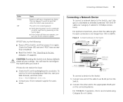
... it on page 43. If these do not resolve the issue: ■ Check the 3Com Knowledgebase for assistance. Figure 3 Connecting Devices to the Switch Baseline 10/100 switch Endstations on switched 100 Mbps connections Baseline 10/100 switch Endstations on switched 100 Mbps connections Baseline Switch 2250 Plus 1000 Mbps link 10 or 100 Mbps link 1000 Mbps copper or fiber connection...
... it on page 43. If these do not resolve the issue: ■ Check the 3Com Knowledgebase for assistance. Figure 3 Connecting Devices to the Switch Baseline 10/100 switch Endstations on switched 100 Mbps connections Baseline 10/100 switch Endstations on switched 100 Mbps connections Baseline Switch 2250 Plus 1000 Mbps link 10 or 100 Mbps link 1000 Mbps copper or fiber connection...

User Guide
Page 18
... label Wire release lever Suitable slot on page 43. Use this transceiver to connect the Switch directly to multimode fiber using 3Com SFPs on the Switch. 18 CHAPTER 2: INSTALLING THE SWITCH Using SFP Transceivers The following sections describe how to insert and remove an SFP transceiver from...as valid, the SFP transceiver must be properly inserted only one of approved SFP transceivers for the Switch on the 3Com Corporation World Wide Web site, enter this transceiver to connect the Switch directly to a single-mode fiber-optic cable or to a multimedia fiber-optic cable. ■...
... label Wire release lever Suitable slot on page 43. Use this transceiver to connect the Switch directly to multimode fiber using 3Com SFPs on the Switch. 18 CHAPTER 2: INSTALLING THE SWITCH Using SFP Transceivers The following sections describe how to insert and remove an SFP transceiver from...as valid, the SFP transceiver must be properly inserted only one of approved SFP transceivers for the Switch on the 3Com Corporation World Wide Web site, enter this transceiver to connect the Switch directly to a single-mode fiber-optic cable or to a multimedia fiber-optic cable. ■...

User Guide
Page 19
...near to the front right hand side of a possible failure; Removing an SFP Transceiver Removing an SFP transceiver does not require powering off the Switch. not click when you should slide out easily. Attach a male duplex LC connector on the network cable into the duplex LC connector on... effect on the front of the cable to a device fitted with an appropriate Gigabit Ethernet connection. 7 Check the Module Active LEDs on users. 3Com recommends periodically checking the items listed in Table 7. To remove an SFP transceiver: 1 Disconnect the cable from the front). Performing Spot Checks At...
...near to the front right hand side of a possible failure; Removing an SFP Transceiver Removing an SFP transceiver does not require powering off the Switch. not click when you should slide out easily. Attach a male duplex LC connector on the network cable into the duplex LC connector on... effect on the front of the cable to a device fitted with an appropriate Gigabit Ethernet connection. 7 Check the Module Active LEDs on users. 3Com recommends periodically checking the items listed in Table 7. To remove an SFP transceiver: 1 Disconnect the cable from the front). Performing Spot Checks At...

User Guide
Page 20
20 CHAPTER 2: INSTALLING THE SWITCH
20 CHAPTER 2: INSTALLING THE SWITCH

User Guide
Page 21
...are available on how the gain access to the Web interface using the Discovery application. If you only want the Switch to function as a basic layer 2 switch, you do the following : ■ The Discovery application, which is included on the CD-ROM, and then...should start automatically, go to the \Discovery folder on 3Com Baseline Switch 2250 Plus CD-ROM that is supplied with your Switch ■ A computer that is connected to the Switch and that has a Web browser Running the Discovery Application The 3Com Baseline Switch 2250 Plus CD-ROM contains, among others, the Discovery application. ...
...are available on how the gain access to the Web interface using the Discovery application. If you only want the Switch to function as a basic layer 2 switch, you do the following : ■ The Discovery application, which is included on the CD-ROM, and then...should start automatically, go to the \Discovery folder on 3Com Baseline Switch 2250 Plus CD-ROM that is supplied with your Switch ■ A computer that is connected to the Switch and that has a Web browser Running the Discovery Application The 3Com Baseline Switch 2250 Plus CD-ROM contains, among others, the Discovery application. ...

User Guide
Page 22
... When detection is complete, the Discovered Devices screen displays detected network devices. 3 On the Discovered Devices screen, click Baseline Switch 2250 Plus, and then click Next. The Completing the 3Com Discovery Application screen appears. 4 Click Finish. Logging On to the Web Interface On the log on dialog box, ...enter the administration user name and password to gain access to the Switch, and then click Next. If the computer has...
... When detection is complete, the Discovered Devices screen displays detected network devices. 3 On the Discovered Devices screen, click Baseline Switch 2250 Plus, and then click Next. The Completing the 3Com Discovery Application screen appears. 4 Click Finish. Logging On to the Web Interface On the log on dialog box, ...enter the administration user name and password to gain access to the Switch, and then click Next. If the computer has...

User Guide
Page 23
...Navigating the Web Interface The Web interface has been designed to enable you to easily perform advanced configuration tasks and view information about the Switch. Menu The menu is located on the menu, the related screen appears in the main part of the Web interface. When you ...click an item on the left side of the interface. Table 8 Available Menu Items Menu Item Description Summary Provides a summary of the Switch's basic settings and versions of current components Password Allows you to change the administrator password IP Settings Allows you to configure the IP address ...
...Navigating the Web Interface The Web interface has been designed to enable you to easily perform advanced configuration tasks and view information about the Switch. Menu The menu is located on the menu, the related screen appears in the main part of the Web interface. When you ...click an item on the left side of the interface. Table 8 Available Menu Items Menu Item Description Summary Provides a summary of the Switch's basic settings and versions of current components Password Allows you to change the administrator password IP Settings Allows you to configure the IP address ...
User Guide
Page 24
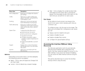
...Without Using Discovery The Discovery application works by automatically detecting the IP address that is assigned to the Switch, and then using Discovery. Click to display the context-sensitive help pages provide information on the ... Item Port Configuration VLANs Trunking Traffic Monitoring System Tools Support Log Out Description Allows you to configure the Switch's port settings Allows you to create VLAN groups, add port members, and specify how VLAN tagging is... tree topology ■ Enable and disable 802.1p prioritization Displays 3Com contact information and describes how to use .
...Without Using Discovery The Discovery application works by automatically detecting the IP address that is assigned to the Switch, and then using Discovery. Click to display the context-sensitive help pages provide information on the ... Item Port Configuration VLANs Trunking Traffic Monitoring System Tools Support Log Out Description Allows you to configure the Switch's port settings Allows you to create VLAN groups, add port members, and specify how VLAN tagging is... tree topology ■ Enable and disable 802.1p prioritization Displays 3Com contact information and describes how to use .


