Getting Started Guide
Page 4
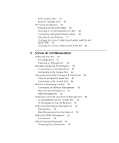
... Port 39 Connecting to the Console Port 42 Viewing Automatically Configured IP Information 46 Using 3Com Network Supervisor 46 Connecting to the Console Port 46 Methods of Managing a Switch 49 Command Line Interface Management 49 Web Interface Management 50 SNMP Management 50 Setting Up Command Line Interface Management 50 CLI Management via the Console Port 50 CLI Management over the Network 51 Setting Up Web Interface Management 52 Pre-requisites 52 Web Management Over the Network 53 Setting Up SNMP Management 53 Pre-requisites 53 Default Users and Passwords 54 Changing Default Passwords...
... Port 39 Connecting to the Console Port 42 Viewing Automatically Configured IP Information 46 Using 3Com Network Supervisor 46 Connecting to the Console Port 46 Methods of Managing a Switch 49 Command Line Interface Management 49 Web Interface Management 50 SNMP Management 50 Setting Up Command Line Interface Management 50 CLI Management via the Console Port 50 CLI Management over the Network 51 Setting Up Web Interface Management 52 Pre-requisites 52 Web Management Over the Network 53 Setting Up SNMP Management 53 Pre-requisites 53 Default Users and Passwords 54 Changing Default Passwords...

Getting Started Guide
Page 14
... entries Auto-negotiation ■ Supported on all ports ■ Auto MDI/MDI-X (not 3C17210) Forwarding Modes Store and Forward Duplex Modes Half and full duplex on all front panel ports Flow Control In full duplex operation all ports are installed in the expansion slots on each port by the Switch 4400. These allow easy connection of 100 Mbps fiber-optic links. Summary of Hardware Features Table 3 summarizes the hardware features that are supported by default. Table 3 Hardware features Feature Switch 4400 Addresses...
... entries Auto-negotiation ■ Supported on all ports ■ Auto MDI/MDI-X (not 3C17210) Forwarding Modes Store and Forward Duplex Modes Half and full duplex on all front panel ports Flow Control In full duplex operation all ports are installed in the expansion slots on each port by the Switch 4400. These allow easy connection of 100 Mbps fiber-optic links. Summary of Hardware Features Table 3 summarizes the hardware features that are supported by default. Table 3 Hardware features Feature Switch 4400 Addresses...

Getting Started Guide
Page 16
... can use the standard MT-RJ The Switch 4400 PWR incorporates a LED Mode Button on the front panel, which when pressed changes the mode of the 24 front panel ports in conformance to 10BASE-T half duplex, 10BASE-T full duplex, 100BASE-TX half duplex or 100BASE-TX full duplex. 16 CHAPTER 1: INTRODUCING THE SUPERSTACK 3 SWITCH 4400 Figure 4 Switch 4400 (48-port) - These are shielded RJ-45 data sockets. Only connect RJ-45 data connectors, network...
... can use the standard MT-RJ The Switch 4400 PWR incorporates a LED Mode Button on the front panel, which when pressed changes the mode of the 24 front panel ports in conformance to 10BASE-T half duplex, 10BASE-T full duplex, 100BASE-TX half duplex or 100BASE-TX full duplex. 16 CHAPTER 1: INTRODUCING THE SUPERSTACK 3 SWITCH 4400 Figure 4 Switch 4400 (48-port) - These are shielded RJ-45 data sockets. Only connect RJ-45 data connectors, network...

Getting Started Guide
Page 18
... user documentation accompanying the module, if installed. Yellow flashing The module has failed and has been automatically disabled. (fast) The Switch passes its Power On Self Test and continues to the port. Green sequential When the Switch is stand-alone and not part of that a link is 4 Hz Module LEDs Packet Refer to unit over Ethernet POST error on . 18 CHAPTER 1: INTRODUCING THE SUPERSTACK 3 SWITCH 4400 LED Color Indicates Port LEDs - Off A fault has occurred. Flash rate is present. Status Refer to software version...
... user documentation accompanying the module, if installed. Yellow flashing The module has failed and has been automatically disabled. (fast) The Switch passes its Power On Self Test and continues to the port. Green sequential When the Switch is stand-alone and not part of that a link is 4 Hz Module LEDs Packet Refer to unit over Ethernet POST error on . 18 CHAPTER 1: INTRODUCING THE SUPERSTACK 3 SWITCH 4400 LED Color Indicates Port LEDs - Off A fault has occurred. Flash rate is present. Status Refer to software version...
Getting Started Guide
Page 19
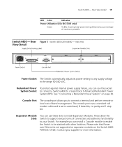
... the Switch 4400 PWR (3C17205). For example you to auto-baud, 8 data bits, no parity and 1 stop bit. Please note that Power over Ethernet is set to connect a terminal and perform remote or local out-of-band management. Rear Figure 5 Switch 4400 (all models) - Console Port The console port allows you can install a Cascade module to enable the Switch to any supply voltage in the range 90-240 VAC. Switch 4400 - The console port uses a standard null modem cable and is not supported...
... the Switch 4400 PWR (3C17205). For example you to auto-baud, 8 data bits, no parity and 1 stop bit. Please note that Power over Ethernet is set to connect a terminal and perform remote or local out-of-band management. Rear Figure 5 Switch 4400 (all models) - Console Port The console port allows you can install a Cascade module to enable the Switch to any supply voltage in the range 90-240 VAC. Switch 4400 - The console port uses a standard null modem cable and is not supported...
Getting Started Guide
Page 20
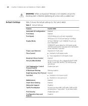
... (3C17205 only) Flow Control ■ Enabled in half-duplex mode ■ Auto-negotiated in full-duplex mode Broadcast Storm Control Enabled Virtual LANs (VLANs) All ports belong to half-duplex mode (100 HD) if required. 20 CHAPTER 1: INTRODUCING THE SUPERSTACK 3 SWITCH 4400 Default Settings WARNING: When an Expansion Module is not installed, ensure the blanking plate is fitted by tightening all other traffic. All ports set to "best effort" for the Switch 4400: Table 5 Default Settings Feature Switch 4400 Automatic IP Configuration Enabled Port Status Enabled Port Speed 10...
... (3C17205 only) Flow Control ■ Enabled in half-duplex mode ■ Auto-negotiated in full-duplex mode Broadcast Storm Control Enabled Virtual LANs (VLANs) All ports belong to half-duplex mode (100 HD) if required. 20 CHAPTER 1: INTRODUCING THE SUPERSTACK 3 SWITCH 4400 Default Settings WARNING: When an Expansion Module is not installed, ensure the blanking plate is fitted by tightening all other traffic. All ports set to "best effort" for the Switch 4400: Table 5 Default Settings Feature Switch 4400 Automatic IP Configuration Enabled Port Status Enabled Port Speed 10...

Getting Started Guide
Page 27
... to order the SuperStack 3 Switch Cascade Stacking Kit (3C17227). The kit consists of two Cascade Modules and a Cascade Cable. If you must use the self-adhesive rubber pads supplied. Any combination of 24-port and 48-port units is allowed in the marked area at the top. An upgraded Switch 4400 SE cannot be positioned at each Switch, sticking one IP address. If you...
... to order the SuperStack 3 Switch Cascade Stacking Kit (3C17227). The kit consists of two Cascade Modules and a Cascade Cable. If you must use the self-adhesive rubber pads supplied. Any combination of 24-port and 48-port units is allowed in the marked area at the top. An upgraded Switch 4400 SE cannot be positioned at each Switch, sticking one IP address. If you...

Getting Started Guide
Page 29
... with SuperStack II or other SuperStack 3 products using the Cascade Stacking Kit (3C17227) or Cascade Extender Kit (3C17228). ■ 3Com strongly recommends that you upgrade all Switch 4400 units (24-port and 48-port) in a stack to the latest software agent. ■ 3Com recommends that you initialize a Switch 4400, Switch 4400 SE, Switch 4400 PWR or Switch 4400 FX unit that the Switch is powered off before you do not initialize the unit, problems may...
... with SuperStack II or other SuperStack 3 products using the Cascade Stacking Kit (3C17227) or Cascade Extender Kit (3C17228). ■ 3Com strongly recommends that you upgrade all Switch 4400 units (24-port and 48-port) in a stack to the latest software agent. ■ 3Com recommends that you initialize a Switch 4400, Switch 4400 SE, Switch 4400 PWR or Switch 4400 FX unit that the Switch is powered off before you do not initialize the unit, problems may...
Getting Started Guide
Page 30
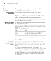
... type 2A Power Modules combined using a Type 2 Y-Cable. Checking for the LED. The Switch is powered-up and operating normally. Connecting a Redundant Power System You can connect a SuperStack 3 Advanced Redundant Power System (3C16071B) to the Switch. The Switch has failed its Power On Self Test (POST), which is also known as an RPS, is evidence of a problem, see "Solving Problems Indicated by LEDs" on the Switch are disabled and the LEDs light in a set sequence. Table 6 Power/Self Test LED...
... type 2A Power Modules combined using a Type 2 Y-Cable. Checking for the LED. The Switch is powered-up and operating normally. Connecting a Redundant Power System You can connect a SuperStack 3 Advanced Redundant Power System (3C16071B) to the Switch. The Switch has failed its Power On Self Test (POST), which is also known as an RPS, is evidence of a problem, see "Solving Problems Indicated by LEDs" on the Switch are disabled and the LEDs light in a set sequence. Table 6 Power/Self Test LED...

Getting Started Guide
Page 32
... 4400 PWR (3C17205) supports Power over Ethernet on the CD-ROM that accompanies your Switch. For further information about Power Over Ethernet, refer to "Power Management and Control" in MDI or MDIX mode. Choosing the Correct Cables (Switch 4400, 4400 SE and 4400 PWR) All of the ports on the 3Com web site http://www.3com.com/. The Auto-MDIX feature only operates when auto-negotiation is available using the web interface or the command line interface (CLI). If you want to make a connection to...
... 4400 PWR (3C17205) supports Power over Ethernet on the CD-ROM that accompanies your Switch. For further information about Power Over Ethernet, refer to "Power Management and Control" in MDI or MDIX mode. Choosing the Correct Cables (Switch 4400, 4400 SE and 4400 PWR) All of the ports on the 3Com web site http://www.3com.com/. The Auto-MDIX feature only operates when auto-negotiation is available using the web interface or the command line interface (CLI). If you want to make a connection to...

Getting Started Guide
Page 35
...-play). 3 SETTING UP FOR MANAGEMENT Your Switch can operate in its default state, that is known as managing the Switch. Managing the Switch can help you have to make full use of your network. This chapter explains the initial set up of the Switch and the different methods of Managing a Switch ■ Setting Up Command Line Interface Management ■ Setting Up Web Interface Management ■ Setting Up SNMP Management ■ Default Users and Passwords However, to access the management software that resides...
...-play). 3 SETTING UP FOR MANAGEMENT Your Switch can operate in its default state, that is known as managing the Switch. Managing the Switch can help you have to make full use of your network. This chapter explains the initial set up of the Switch and the different methods of Managing a Switch ■ Setting Up Command Line Interface Management ■ Setting Up Web Interface Management ■ Setting Up SNMP Management ■ Default Users and Passwords However, to access the management software that resides...
Getting Started Guide
Page 37
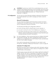
... management simpler and more information on default users and changing default passwords, see "Default Users and Passwords" on page 54. If this default IP address is already in use the Manual IP configuration method if: ■ you do not have this and configures itself with an IP address in a standalone mode, and/or no other Switches on the network have a DHCP or BootP server on your network, or ■ you want to remove...
... management simpler and more information on default users and changing default passwords, see "Default Users and Passwords" on page 54. If this default IP address is already in use the Manual IP configuration method if: ■ you do not have this and configures itself with an IP address in a standalone mode, and/or no other Switches on the network have a DHCP or BootP server on your network, or ■ you want to remove...
Getting Started Guide
Page 38
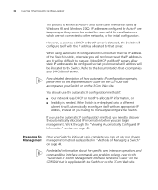
... 3Com Web site. For detailed information about the specific web interface operations and command line interface commands and problem solving, refer to the "SuperStack 3 Switch Management Interface Reference Guide" on the CD-ROM that is supplied with an appropriate IP address, instead of how automatic IP configuration operates, please refer to manage. 38 CHAPTER 3: SETTING UP FOR MANAGEMENT This process is known as they cannot be routed but are useful for small networks which are temporary as Auto...
... 3Com Web site. For detailed information about the specific web interface operations and command line interface commands and problem solving, refer to the "SuperStack 3 Switch Management Interface Reference Guide" on the CD-ROM that is supplied with an appropriate IP address, instead of how automatic IP configuration operates, please refer to manage. 38 CHAPTER 3: SETTING UP FOR MANAGEMENT This process is known as they cannot be routed but are useful for small networks which are temporary as Auto...

Getting Started Guide
Page 40
... address - 169.254.100.99 ■ Subnet mask - 255.255.0.0 Setting Up the Switch with IP Information You are now ready to manually set up the Switch. This is automatically assigned to an offline unit. 40 CHAPTER 3: SETTING UP FOR MANAGEMENT Connecting the Workstation to the Switch 1 Connect the workstation to a front panel port using the Web interface or the command line interface (CLI) via a front panel port To connect the cable...
... address - 169.254.100.99 ■ Subnet mask - 255.255.0.0 Setting Up the Switch with IP Information You are now ready to manually set up the Switch. This is automatically assigned to an offline unit. 40 CHAPTER 3: SETTING UP FOR MANAGEMENT Connecting the Workstation to the Switch 1 Connect the workstation to a front panel port using the Web interface or the command line interface (CLI) via a front panel port To connect the cable...

Getting Started Guide
Page 44
... as the Switch detects a connection to its console port. If the login prompt does not begin immediately, press Return a few times until it starts. 2 At the login and password prompts, enter admin as shown in the example in Figure 13. If you have logged on correctly, the top-level menu of the command line interface is displayed as your terminal emulation software and configure the COM port settings to which...
... as the Switch detects a connection to its console port. If the login prompt does not begin immediately, press Return a few times until it starts. 2 At the login and password prompts, enter admin as shown in the example in Figure 13. If you have logged on correctly, the top-level menu of the command line interface is displayed as your terminal emulation software and configure the COM port settings to which...

Getting Started Guide
Page 50
... remotely over the network. SNMP Management You can manage a Switch using the command line interface via its console port. For example, you can set of web pages that accompanies your Switch. CLI Management via To manage a Switch using any network management workstation running the Simple Network Management Protocol (SNMP) as described in "Connecting to the console port correctly as shown in Figure 19. Figure 18 Web interface management over the network Refer to "Setting Up SNMP Management" on the CD-ROM that allow you can use the 3Com Network Supervisor software...
... remotely over the network. SNMP Management You can manage a Switch using the command line interface via its console port. For example, you can set of web pages that accompanies your Switch. CLI Management via To manage a Switch using any network management workstation running the Simple Network Management Protocol (SNMP) as described in "Connecting to the console port correctly as shown in Figure 19. Figure 18 Web interface management over the network Refer to "Setting Up SNMP Management" on the CD-ROM that allow you can use the 3Com Network Supervisor software...

Getting Started Guide
Page 53
... Device View button to the Switch using the web interface over an IP network: Over the Network 1 Check that you use the 3Com Network Supervisor application that accompanies your Switch to browse the World Wide Web. Setting Up SNMP Management 53 Web Management To manage a Switch using a port in VLAN 1. Setting Up SNMP Management Any network management application running the Simple Network Management Protocol (SNMP) can communicate with the SNMP network management application software. By default, all ports on the CD-ROM that is connected to display the web management...
... Device View button to the Switch using the web interface over an IP network: Over the Network 1 Check that you use the 3Com Network Supervisor application that accompanies your Switch to browse the World Wide Web. Setting Up SNMP Management 53 Web Management To manage a Switch using a port in VLAN 1. Setting Up SNMP Management Any network management application running the Simple Network Management Protocol (SNMP) can communicate with the SNMP network management application software. By default, all ports on the CD-ROM that is connected to display the web management...

Getting Started Guide
Page 54
... and change all manageable parameters, except special/security features, but not special/security features (no password) to the "Superstack 3 Switch Management Interface Reference Guide" on the Switch. Default Users and Passwords If you do this using an SNMP network management application, you need to specify SNMP community strings for more information about default users and passwords, refer to login and carry out initial Switch setup. 54 CHAPTER 3: SETTING UP FOR MANAGEMENT To manage your Switch Table 9 Default Users User Name monitor manager admin Default Password...
... and change all manageable parameters, except special/security features, but not special/security features (no password) to the "Superstack 3 Switch Management Interface Reference Guide" on the Switch. Default Users and Passwords If you do this using an SNMP network management application, you need to specify SNMP community strings for more information about default users and passwords, refer to login and carry out initial Switch setup. 54 CHAPTER 3: SETTING UP FOR MANAGEMENT To manage your Switch Table 9 Default Users User Name monitor manager admin Default Password...
Getting Started Guide
Page 87
... 87 E Ethernet address of the Switch 26 F factory defaults 20 H hardware features 14 I installing the Switch 23 prerequisites 24 IP addressing registered 60 IP configuration 37 L LEDs 17 logging in as a default user 54 M MAC address of the Switch 26 management methods 49 preparing for 38 setting up 35, 36 manual setup console port 42 front panel port 39 MDI configuration 32 MDIX configuration 32 N network supplier support 82 O online technical services 81 P passwords of default users 54 pin assignments modem cable 72...
... 87 E Ethernet address of the Switch 26 F factory defaults 20 H hardware features 14 I installing the Switch 23 prerequisites 24 IP addressing registered 60 IP configuration 37 L LEDs 17 logging in as a default user 54 M MAC address of the Switch 26 management methods 49 preparing for 38 setting up 35, 36 manual setup console port 42 front panel port 39 MDI configuration 32 MDIX configuration 32 N network supplier support 82 O online technical services 81 P passwords of default users 54 pin assignments modem cable 72...
Getting Started Guide
Page 88
... support 3Com Knowledgebase Web Services 82 3Com URL 81 network suppliers 82 product repair 85 troubleshooting 55 U unit information label 26 URL 81 W Web browsers choosing 52 web interface choosing a browser 52 web interface management 50 setting up a Switch 4400 30 problem solving 55 communication problems 60 hardware problems 57 IP addressing 57 LEDs 56 product name 26 R rack mounting a Switch 4400 25 Redundant Power System. See console port Simple Network Management Protocol. See RPS related documentation 9 returning products for repair 85 RPS 19 connecting...
... support 3Com Knowledgebase Web Services 82 3Com URL 81 network suppliers 82 product repair 85 troubleshooting 55 U unit information label 26 URL 81 W Web browsers choosing 52 web interface choosing a browser 52 web interface management 50 setting up a Switch 4400 30 problem solving 55 communication problems 60 hardware problems 57 IP addressing 57 LEDs 56 product name 26 R rack mounting a Switch 4400 25 Redundant Power System. See console port Simple Network Management Protocol. See RPS related documentation 9 returning products for repair 85 RPS 19 connecting...


