Service Manual
Page 1
AM-HX50 AHK1(S) AM-HX55 AHK1(L,W) SERVICE MANUAL MINIDISC PLAYER BASIC MD MECHANISM : ZZG-5 A This Service Manual is the "Revision Publishing" and replaces "Simple Manual" (S/M Code No.09-999-335-5T2). S/M Code No. 09-999-335-5R2 REVISDIAOTAN
AM-HX50 AHK1(S) AM-HX55 AHK1(L,W) SERVICE MANUAL MINIDISC PLAYER BASIC MD MECHANISM : ZZG-5 A This Service Manual is the "Revision Publishing" and replaces "Simple Manual" (S/M Code No.09-999-335-5T2). S/M Code No. 09-999-335-5R2 REVISDIAOTAN
Service Manual
Page 2
Under license from Dolby Laboratories Licensing Corporation. SPECIFICATIONS • Design and specifications are trademarks of BBE Sound,Inc. "DOLBY" and the double-D symbol are trademarks of Dolby Laboratories Licensing Corporation. • The word "BBE" and the "BBE symbol" are subject to change without notice. • Dolby noise reduction manufactured under license from BBE Sound,Inc. 2
Under license from Dolby Laboratories Licensing Corporation. SPECIFICATIONS • Design and specifications are trademarks of BBE Sound,Inc. "DOLBY" and the double-D symbol are trademarks of Dolby Laboratories Licensing Corporation. • The word "BBE" and the "BBE symbol" are subject to change without notice. • Dolby noise reduction manufactured under license from BBE Sound,Inc. 2
Service Manual
Page 3
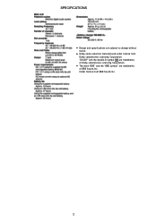
... when open and interlocks defeated avoid exposure to replace Optical block...use care the clothes do not touch the diode. 1) After the connection, remove solder shown in hazardous radiation exposure. The CLASS 1 LASER PRODUCT label is classified as a CLASS 1 LASER product. VARNING! CLASS 1 LASER PRODUCT KLASSE 1 LASER PRODUKT LUOKAN 1 LASER LAITE KLASS 1 LASER APPARAT Precaution to beam. PROTECTION OF EYES FROM LASER BEAM DURING SERVICING This set... employs laser. Therefore, be sure to follow carefully the instructions below when servicing. WARNING! WHEN SERVICING...
... when open and interlocks defeated avoid exposure to replace Optical block...use care the clothes do not touch the diode. 1) After the connection, remove solder shown in hazardous radiation exposure. The CLASS 1 LASER PRODUCT label is classified as a CLASS 1 LASER product. VARNING! CLASS 1 LASER PRODUCT KLASSE 1 LASER PRODUKT LUOKAN 1 LASER LAITE KLASS 1 LASER APPARAT Precaution to beam. PROTECTION OF EYES FROM LASER BEAM DURING SERVICING This set... employs laser. Therefore, be sure to follow carefully the instructions below when servicing. WARNING! WHEN SERVICING...
Service Manual
Page 4
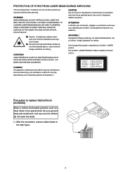
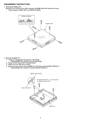
Removing the MAIN C.B 1) Connect the shorting lands of the pickup by a solder bridge. * When the MAIN C.B is attached, remove the solder bridge. 2) Remove the FFC of the CN300, CN700 and CN100. 3) Remove the screw A*3 and screw B*1. 4) Remove the battery lid and remove the ... The BAT-CONTACT + is attached, be careful of the arrow. * When attaching the PANEL, BOT, set the KNOB, SL HOLD. DISASSEMBLY INSTRUCTIONS 1. KNOB, SL HOLD B B PANEL, BOT A B B B B 2. Removing the PANEL, BOT Remove the screw A*1 and screw B*6, and remove the PANEL, BOT in the direction of the BAT-CONTACT +.
Removing the MAIN C.B 1) Connect the shorting lands of the pickup by a solder bridge. * When the MAIN C.B is attached, remove the solder bridge. 2) Remove the FFC of the CN300, CN700 and CN100. 3) Remove the screw A*3 and screw B*1. 4) Remove the battery lid and remove the ... The BAT-CONTACT + is attached, be careful of the arrow. * When attaching the PANEL, BOT, set the KNOB, SL HOLD. DISASSEMBLY INSTRUCTIONS 1. KNOB, SL HOLD B B PANEL, BOT A B B B B 2. Removing the PANEL, BOT Remove the screw A*1 and screw B*6, and remove the PANEL, BOT in the direction of the BAT-CONTACT +.

Service Manual
Page 5
A A B PANEL ASSY, TOP B A A A 4. HLDR, CTRG A 5 Removing the HLDR, CTRG Remove the HLDR, CTRG by bending both sides of the HLDR, CTRG to bend portion A. Removing the PANEL ASSY, TOP Remove the screw A*5 and unlock the claw B of the HLDR, CTRG. * Be careful not to remove the PANEL ASSY, TOP. 3.
A A B PANEL ASSY, TOP B A A A 4. HLDR, CTRG A 5 Removing the HLDR, CTRG Remove the HLDR, CTRG by bending both sides of the HLDR, CTRG to bend portion A. Removing the PANEL ASSY, TOP Remove the screw A*5 and unlock the claw B of the HLDR, CTRG. * Be careful not to remove the PANEL ASSY, TOP. 3.

Service Manual
Page 8
... • Regarding connectors, they are not stocked as they are not the initial order items. The connectors are available after they are supplied from connector manufacturers upon the order is received. REF. CHIP RESISTOR PART CODE Chip Resistor Part Coding 88 A Resistor Code Chip resistor Wattage 1/16W 1/16W 1/10W 1/8W Type 1005 1608 2125 3216 Tolerance...
... • Regarding connectors, they are not stocked as they are not the initial order items. The connectors are available after they are supplied from connector manufacturers upon the order is received. REF. CHIP RESISTOR PART CODE Chip Resistor Part Coding 88 A Resistor Code Chip resistor Wattage 1/16W 1/16W 1/10W 1/8W Type 1005 1608 2125 3216 Tolerance...
Service Manual
Page 15
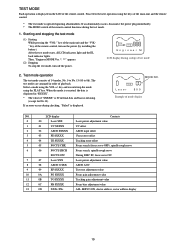
... control. * The test mode is displayed. Proceed to 0d). Test mode operation The test mode consists of "$XXXX" is IC internal data and has no meaning. (except for No.13). If an error occurs during checking, "Failed" is operated ignoring abnormalities. Select a mode using the keys of the remote control, turn off the power. When the mode is executed, the data is displayed in order of mode display NO. MODE...
... control. * The test mode is displayed. Proceed to 0d). Test mode operation The test mode consists of "$XXXX" is IC internal data and has no meaning. (except for No.13). If an error occurs during checking, "Failed" is operated ignoring abnormalities. Select a mode using the keys of the remote control, turn off the power. When the mode is executed, the data is displayed in order of mode display NO. MODE...
Service Manual
Page 16
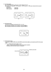
... the OPEN/CLOSE switch and the HOLD switch of the disc holder can be checked on . The operation cycles among OFF ™ PIT laser power ™ GRV laser power ™ OFF repeats each time the key is not displayed. Move the pickup to the DISC inner circumference using the F-SKIP key. (1) Laser power check Press the DISP/SEARCH key of the remote control...
... the OPEN/CLOSE switch and the HOLD switch of the disc holder can be checked on . The operation cycles among OFF ™ PIT laser power ™ GRV laser power ™ OFF repeats each time the key is not displayed. Move the pickup to the DISC inner circumference using the F-SKIP key. (1) Laser power check Press the DISP/SEARCH key of the remote control...
Service Manual
Page 17
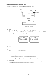
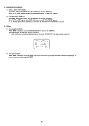
...not adjust manually. • If "NO ADJ" appears during normal use, it means that the adjustment has not completed. (5) Prohibited items Do not press the MODE or DSL/ENTER key of the remote control. Starting and stopping the adjustment mode Operation of the adjustment mode is dirty... the STOP key to display "IDLE". PRGM RNDM 1 TR NO. Ma n u f ac t u r TR NO. When changing the data in this enters the mode for factory use. I DLE (2) Stopping To stop the adjustment mode, turn on the power (by installing the battery). When the adjustment mode starts, the EL back indicator...
...not adjust manually. • If "NO ADJ" appears during normal use, it means that the adjustment has not completed. (5) Prohibited items Do not press the MODE or DSL/ENTER key of the remote control. Starting and stopping the adjustment mode Operation of the adjustment mode is dirty... the STOP key to display "IDLE". PRGM RNDM 1 TR NO. Ma n u f ac t u r TR NO. When changing the data in this enters the mode for factory use. I DLE (2) Stopping To stop the adjustment mode, turn on the power (by installing the battery). When the adjustment mode starts, the EL back indicator...
Service Manual
Page 18
...the LCD of the remote control, "COMPLETE" appears. (2) GRV disc (SONY MDW-74) Insert a disc and press the "PLAY" key. (Be careful of the direction of the unit.) After... "AUTO ADJ L" appears on the LCD. * After initialization, perform the adjustment again, otherwise "NO ADJUST!" TR NO. 4. Others (1) Initializing the EEPROM While "IDLE" is displayed...OK (2) Sled operation check While "IDLE" is displayed, press the DISP/SEARCH key to an error. 5. After initialization, "EP INIT OK" appears on the LCD of the remote control, "COMPLETE" ...
...the LCD of the remote control, "COMPLETE" appears. (2) GRV disc (SONY MDW-74) Insert a disc and press the "PLAY" key. (Be careful of the direction of the unit.) After... "AUTO ADJ L" appears on the LCD. * After initialization, perform the adjustment again, otherwise "NO ADJUST!" TR NO. 4. Others (1) Initializing the EEPROM While "IDLE" is displayed...OK (2) Sled operation check While "IDLE" is displayed, press the DISP/SEARCH key to an error. 5. After initialization, "EP INIT OK" appears on the LCD of the remote control, "COMPLETE" ...
Service Manual
Page 19
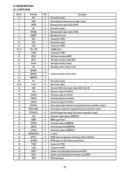
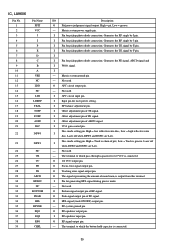
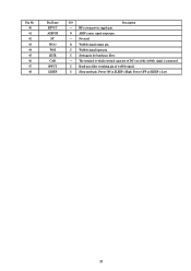
... KEY1 FOK I/O Description O Not used (L output). - I Standby cancel signal input from EEPROM. I Serial data input from remote control KEY. I A/D input of drive voltage of battery voltage. I Microprocessor reset. - O PWM output for VM control of remote control KEY. O Not used (L output). I O Not used (L output). O Serial data output to GND. O PWM output for writing flash memory (normally L output). I A/D input of motor driver. - Connected to EEPROM. O Chip select...
... KEY1 FOK I/O Description O Not used (L output). - I Standby cancel signal input from EEPROM. I Serial data input from remote control KEY. I A/D input of drive voltage of battery voltage. I Microprocessor reset. - O PWM output for VM control of remote control KEY. O Not used (L output). I O Not used (L output). O Serial data output to GND. O PWM output for writing flash memory (normally L output). I A/D input of motor driver. - Connected to EEPROM. O Chip select...

Service Manual
Page 20
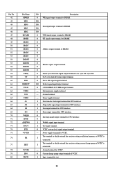
.... O Outputs H during data read. I FSEQ signal input from LC89641. I Holder OPEN (H)/CLOSE (L) signal input and standby cancel. I PPIT signal input. I Domestic version/foreign version switching input (domestic version at H). I HOLD signal input (HOLD ON at L). Control selector signal output (controlled by microprocessor at H). O System power supply control (power ON at L). I Monitor 0 signal input from LC89641. I VP (CLV servo lock judgement) signal input. Connected to DRAM...
.... O Outputs H during data read. I FSEQ signal input from LC89641. I Holder OPEN (H)/CLOSE (L) signal input and standby cancel. I PPIT signal input. I Domestic version/foreign version switching input (domestic version at H). I HOLD signal input (HOLD ON at L). Control selector signal output (controlled by microprocessor at H). O System power supply control (power ON at L). I Monitor 0 signal input from LC89641. I VP (CLV servo lock judgement) signal input. Connected to DRAM...

Service Manual
Page 21
... terminal. O Audio extended data output terminal. O Digital audio output terminal. - O ABCD offset control signal output terminal. Internal power supply terminal. O 1BIT DAC L-channel output terminal. O 1BIT DAC R-channel output terminal. - Power supply terminal. Ground terminal. - O Laser control signal output terminal. O O Focus PWM output terminal. Ground terminal for 16.9344 MHz oscillation. - O Focus offset control signal output terminal. O LR clock output...
... terminal. O Audio extended data output terminal. O Digital audio output terminal. - O ABCD offset control signal output terminal. Internal power supply terminal. O 1BIT DAC L-channel output terminal. O 1BIT DAC R-channel output terminal. - Power supply terminal. Ground terminal. - O Laser control signal output terminal. O O Focus PWM output terminal. Ground terminal for 16.9344 MHz oscillation. - O Focus offset control signal output terminal. O LR clock output...
Service Manual
Page 22
... signal output terminal to which external bias resistor setting oscillation frequency of VCEC. O Focus OK signal output terminal. I Data transfer clock input terminal for VCEC. O VCEC system clock signal output terminal. - O O O Address output terminal to which external bias resistor setting current charge pump of VCEC is I Wobble signal input terminal. Power supply terminal for CPU interface. Ground terminal...
... signal output terminal to which external bias resistor setting oscillation frequency of VCEC. O Focus OK signal output terminal. I Data transfer clock input terminal for VCEC. O VCEC system clock signal output terminal. - O O O Address output terminal to which external bias resistor setting current charge pump of VCEC is I Wobble signal input terminal. Power supply terminal for CPU interface. Ground terminal...
Service Manual
Page 23
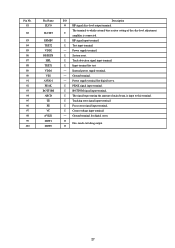
... O 27 I Focus error signal input terminal. Power supply terminal. I BOTTOM signal input terminal. I /O Description O HF signal slice level output terminal. Internal power supply terminal. - O Disc mode switching output. Pin No....reset. I Tracking error signal input terminal. I amplifier is input to which external bias resistor setting of main beam, is connected. The terminal to this terminal. I HF signal input terminal. Ground terminal for test. - I PEAK signal input terminal. I Test input terminal. - Power supply terminal for digital...
... O 27 I Focus error signal input terminal. Power supply terminal. I BOTTOM signal input terminal. I /O Description O HF signal slice level output terminal. Internal power supply terminal. - O Disc mode switching output. Pin No....reset. I Tracking error signal input terminal. I amplifier is input to which external bias resistor setting of main beam, is connected. The terminal to this terminal. I HF signal input terminal. Ground terminal for test. - I PEAK signal input terminal. I Test input terminal. - Power supply terminal for digital...

Service Manual
Page 24
.... The terminal to which slope capacitor is connected. - Spindle power block power supply 1. - Not used . - I Half bridge 1 input. Not used . GND for small signal circuit. (MOS). 28 Not used . Spindle power block power supply 1. O H bridge 2 reverse polarity output. - O H bridge 2 power forward polarity output. - H bridge 2 power block GND1. - I SP IN detection comparator input (U-phase). - Not used . I Half bridge 2 input. The terminal 2 to...
.... The terminal to which slope capacitor is connected. - Spindle power block power supply 1. - Not used . - I Half bridge 1 input. Not used . GND for small signal circuit. (MOS). 28 Not used . Spindle power block power supply 1. O H bridge 2 reverse polarity output. - O H bridge 2 power forward polarity output. - H bridge 2 power block GND1. - I SP IN detection comparator input (U-phase). - Not used . I Half bridge 2 input. The terminal 2 to...

Service Manual
Page 25
... GND2. - O STEP detection comparator output (U-phase). Not used . O Half bridge 2 GND. - Not used. O STEP detection comparator output (V-phase). O Stepping motor output (W-phase). - Half bridge 1 power block power supply. - I STEP motor coil center point input terminal. - I H bridge 2 reverse input. O CHARGEPUMP output. Half bridge 2 power block power supply. 29 I Sync clock input terminal. - Pin No. 42 43 44 45 46...
... GND2. - O STEP detection comparator output (U-phase). Not used . O Half bridge 2 GND. - Not used. O STEP detection comparator output (V-phase). O Stepping motor output (W-phase). - Half bridge 1 power block power supply. - I STEP motor coil center point input terminal. - I H bridge 2 reverse input. O CHARGEPUMP output. Half bridge 2 power block power supply. 29 I Sync clock input terminal. - Pin No. 42 43 44 45 46...
Service Manual
Page 26
...of RF signal. Generates the RF single by E pin. O Tracking error signal output pin. Not used . - O RF signal output pin. - The terminal to which the button-hold capacitor is connected. The terminal to which pass-through capacitor for pickup photo diode connection. I /O Description...RFO 39 CHFL I Pin for generating HFL signal during groove mode. - Disc mode setting pin. I Input pin for laser power setting. Generates the TE signal by J pin. Generates the TE signal by I Pin for 1/2 VCC is connected. 30 I Offset adjustment pin ...
...of RF signal. Generates the RF single by E pin. O Tracking error signal output pin. Not used . - O RF signal output pin. - The terminal to which the button-hold capacitor is connected. The terminal to which pass-through capacitor for pickup photo diode connection. I /O Description...RFO 39 CHFL I Pin for generating HFL signal during groove mode. - Disc mode setting pin. I Input pin for laser power setting. Generates the TE signal by J pin. Generates the TE signal by I Pin for 1/2 VCC is connected. 30 I Offset adjustment pin ...
Service Manual
Page 27
I Band-pass filter switching pin of the wobble signal is connected. The terminal to which external capacitor of DC-cut of wobble signal. I Wobble signal input pin. I /O Description - Power ON at SLEEP = Low. 31 Pin No. 40 41 42 43 44 45 46 47 48 Pin Name RFVCC ADIPCR NC WOO WOI SETR CAD BWCT SLEEP I Setting pin for band-pass filter. - O ADIP carrier signal output pin. - I Sleep mode pin. RF system power supply pin. O Wobble signal output pin. Power OFF at SLEEP = High. Not used.
I Band-pass filter switching pin of the wobble signal is connected. The terminal to which external capacitor of DC-cut of wobble signal. I Wobble signal input pin. I /O Description - Power ON at SLEEP = Low. 31 Pin No. 40 41 42 43 44 45 46 47 48 Pin Name RFVCC ADIPCR NC WOO WOI SETR CAD BWCT SLEEP I Setting pin for band-pass filter. - O ADIP carrier signal output pin. - I Sleep mode pin. RF system power supply pin. O Wobble signal output pin. Power OFF at SLEEP = High. Not used.
Service Manual
Page 29
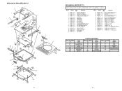
...-017-010 KNOB,SL HOLD KNOB,SL HOLD H(D) PANEL,BOT HK... B Black C Cream D Orange G Green H Gray L Blue LT Transparent Blue N Gold P Pink R Red S Silver... ST Titan Silver T Brown V Violet W White WT Transparent White Y Yellow YT Transparent Yellow LM Metallic Blue LL Light Blue GT Transparent Green LD Dark Blue DT Transparent Orange 34 MECHANICAL EXPLODED VIEW 1/1 3 B 4 J701 ZZG-5 A P.C.B C 5 P.C.B 6 P.C.B A b c 7 F 10 11 12 B D 13 14 A 8 9 a B 1 E 15 16 17 18 B b D E E 19 E F c E 20 E E 33 MECHANICAL PARTS LIST...
...-017-010 KNOB,SL HOLD KNOB,SL HOLD H(D) PANEL,BOT HK... B Black C Cream D Orange G Green H Gray L Blue LT Transparent Blue N Gold P Pink R Red S Silver... ST Titan Silver T Brown V Violet W White WT Transparent White Y Yellow YT Transparent Yellow LM Metallic Blue LL Light Blue GT Transparent Green LD Dark Blue DT Transparent Orange 34 MECHANICAL EXPLODED VIEW 1/1 3 B 4 J701 ZZG-5 A P.C.B C 5 P.C.B 6 P.C.B A b c 7 F 10 11 12 B D 13 14 A 8 9 a B 1 E 15 16 17 18 B b D E E 19 E F c E 20 E E 33 MECHANICAL PARTS LIST...


