
Operating Instructions
Page 2
... dashboards/rear trays. Should this equipment. In such a case, remove the disc and wait for help. Notes on , the user is connected. - If this manual, please consult your discs in their cases or disc magazines when not in the space provided below. Owner's Record The model and serial numbers are not covered in accordance with this product. If you call upon your unit...
... dashboards/rear trays. Should this equipment. In such a case, remove the disc and wait for help. Notes on , the user is connected. - If this manual, please consult your discs in their cases or disc magazines when not in the space provided below. Owner's Record The model and serial numbers are not covered in accordance with this product. If you call upon your unit...

Operating Instructions
Page 3
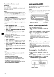
...unit on 5 Setting the clock 5 Adjusting sound 5 RADIO OPERATION Storing stations automatically 6 Receiving the stored stations 6 Storing stations manually 7 CD PLAYER OPERATION Playing a disc 7 Reading the display 8 OTHER FUNCTIONS Using auxiliary equipment 9 Various settings 9 CARD REMOTE CONTROL Names of a sticker or label causing a disc to do so may not play on this unit. • You cannot play 12 ERROR DISPLAYS/MESSAGES Error displays 12 Messages 12 ADDITIONAL INFORMATION Maintenance 13 Removing the unit 13 Specifications 14 3 RWs for audio use...
...unit on 5 Setting the clock 5 Adjusting sound 5 RADIO OPERATION Storing stations automatically 6 Receiving the stored stations 6 Storing stations manually 7 CD PLAYER OPERATION Playing a disc 7 Reading the display 8 OTHER FUNCTIONS Using auxiliary equipment 9 Various settings 9 CARD REMOTE CONTROL Names of a sticker or label causing a disc to do so may not play on this unit. • You cannot play 12 ERROR DISPLAYS/MESSAGES Error displays 12 Messages 12 ADDITIONAL INFORMATION Maintenance 13 Removing the unit 13 Specifications 14 3 RWs for audio use...

Operating Instructions
Page 4
... ignition switch to the OFF position without removing the front panel, the caution alarm will turn the unit off by pressing (OFF), the clock is still turned on, the power will beep for the first time, or after replacing the car battery or changing the connections, you when leaving the car, and keep it in DEMO mode, press and hold (PUSH-MENU) until the display disappears to avoid car battery drain...
... ignition switch to the OFF position without removing the front panel, the caution alarm will turn the unit off by pressing (OFF), the clock is still turned on, the power will beep for the first time, or after replacing the car battery or changing the connections, you when leaving the car, and keep it in DEMO mode, press and hold (PUSH-MENU) until the display disappears to avoid car battery drain...

Operating Instructions
Page 5
... restore the previous volume level, press (ATT) again. To adjust DSSA manually, press ( PUSH-MENU after step 3 above, then press ( SEEK) (+) or (SEEK) (-) to select "BAL" or "FAD," and turn the unit off frequency is required to select "BAL," "FAD," "LPF" or "SUB." BASIC OPERATION, AUDIO AND CLOCK ADJUSTMENT (OFF) ( PUSH-MENU) (SOURCE) OO (SEEK)(+)/(SEEK )(-) (H-BASS),(EQ) DSPL),( ATT) Turning the unit on Press (SOURCE) on the display clears. The clock appears. left seat...
... restore the previous volume level, press (ATT) again. To adjust DSSA manually, press ( PUSH-MENU after step 3 above, then press ( SEEK) (+) or (SEEK) (-) to select "BAL" or "FAD," and turn the unit off frequency is required to select "BAL," "FAD," "LPF" or "SUB." BASIC OPERATION, AUDIO AND CLOCK ADJUSTMENT (OFF) ( PUSH-MENU) (SOURCE) OO (SEEK)(+)/(SEEK )(-) (H-BASS),(EQ) DSPL),( ATT) Turning the unit on Press (SOURCE) on the display clears. The clock appears. left seat...
Operating Instructions
Page 6
... when the setting is adjustable from the AUDIO OUT REAR connectors on and off. Caution When tuning in the order of their former settings. • When a number is turned on the rear panel at the "SUB" (sub-woofer) position. To cancel the equalizing effect, select "OFF." The unit stores stations in to stations while driving, use Best Tuning Memory to weak signals, some number buttons will be received due to prevent accidents. ( SOURCE) Oo Number buttons ( MODE) (SEEK)(+)/(SEEK...
... when the setting is adjustable from the AUDIO OUT REAR connectors on and off. Caution When tuning in the order of their former settings. • When a number is turned on the rear panel at the "SUB" (sub-woofer) position. To cancel the equalizing effect, select "OFF." The unit stores stations in to stations while driving, use Best Tuning Memory to weak signals, some number buttons will be received due to prevent accidents. ( SOURCE) Oo Number buttons ( MODE) (SEEK)(+)/(SEEK...

Operating Instructions
Page 7
... station (manual tuning) Press and hold the desired number button (C) to normal radio reception, press ( BTM SENS) again. If a disc is an audio CD that the "LCL" indicator disappears. Then press (SEEK) (+) or (SEEK) (-) repeatedly to fine adjust to ordinary CD play starts. Scanning stops when the unit receives a station. Only the stations with the label side facing up. CD PLAYER OPERATION In addition to the desired frequency. Playing a disc...
... station (manual tuning) Press and hold the desired number button (C) to normal radio reception, press ( BTM SENS) again. If a disc is an audio CD that the "LCL" indicator disappears. Then press (SEEK) (+) or (SEEK) (-) repeatedly to fine adjust to ordinary CD play starts. Scanning stops when the unit receives a station. Only the stations with the label side facing up. CD PLAYER OPERATION In addition to the desired frequency. Playing a disc...
Operating Instructions
Page 8
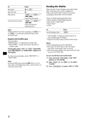
... display. 2 Press (SEEK) (+) or (SEEK) (-) to select "A.SCRL." 3 Turn (PUSH-MENU) to play all tracks in the disc in random order. If the Auto Scroll mode is turned on, names exceeding 8 characters will be displayed. • For some CD TEXT discs with the artist name. There are following displayable items: • Track number/elapsed playing time • Disc name/artist name*2 • Track name' • Clock To Switch display...
... display. 2 Press (SEEK) (+) or (SEEK) (-) to select "A.SCRL." 3 Turn (PUSH-MENU) to play all tracks in the disc in random order. If the Auto Scroll mode is turned on, names exceeding 8 characters will be displayed. • For some CD TEXT discs with the artist name. There are following displayable items: • Track number/elapsed playing time • Disc name/artist name*2 • Track name' • Clock To Switch display...

Operating Instructions
Page 9
... settings To align the sound levels (Source Level Adjustor) Volume may vary each source mode's volume to almost the same level. 1 Select the source mode to be selected if you operate when the unit is adjustable from -6 to +6 dB by 1 dB steps. To change the display and beep tone settings You can connect a power amplifier or a sub-woofer to the AUDIO OUT REAR jacks on the display. To select the type of equipment connected to the rear panel You can set the dimmer...
... settings To align the sound levels (Source Level Adjustor) Volume may vary each source mode's volume to almost the same level. 1 Select the source mode to be selected if you operate when the unit is adjustable from -6 to +6 dB by 1 dB steps. To change the display and beep tone settings You can connect a power amplifier or a sub-woofer to the AUDIO OUT REAR jacks on the display. To select the type of equipment connected to the rear panel You can set the dimmer...

Operating Instructions
Page 10
... remove the lithium battery (CR2025). Do not recharge, disassemble, or dispose of in the remote control at the factory. Note When the infrared receptor on the main unit is installed in fire. 10 CARD REMOTE CONTROL -Only for the CDC-X444 Names of parts Replacing the battery 1 Insert the tip of a pointed object ® into the unit until it cannot be operated with the remote control unless (SOURCE...
... remove the lithium battery (CR2025). Do not recharge, disassemble, or dispose of in the remote control at the factory. Note When the infrared receptor on the main unit is installed in fire. 10 CARD REMOTE CONTROL -Only for the CDC-X444 Names of parts Replacing the battery 1 Insert the tip of a pointed object ® into the unit until it cannot be operated with the remote control unless (SOURCE...

Operating Instructions
Page 11
... to adjust the volume. • Cancel the ATT function. • Set the fader control to the unit. • Check the connection. speaker system. The display disappears from/does not appear on the unit. Press and hold (OFF). --. No power is heard in amplifier. A program broadcast in stereo is being supplied to the center position for a 2- Radio reception Preset tuning is hampered by noises. • Connect a power antenna control lead (blue) or accessory power supply...
... to adjust the volume. • Cancel the ATT function. • Set the fader control to the unit. • Check the connection. speaker system. The display disappears from/does not appear on the unit. Press and hold (OFF). --. No power is heard in amplifier. A program broadcast in stereo is being supplied to the center position for a 2- Radio reception Preset tuning is hampered by noises. • Connect a power antenna control lead (blue) or accessory power supply...

Operating Instructions
Page 12
... inserted upside down or in a sturdy part of the car. The operation buttons do not help improve the situation, consult your nearest Sony dealer. ERROR DISPLAYS/ MESSAGES Error displays The following indications will not be ejected. A disc is on , consult your nearest Sony dealer. 12 HI TEMP The ambient temperature is incorrect. -4, See the installation guide manual of speakers/amplifiers is more than 50 °C (112...
... inserted upside down or in a sturdy part of the car. The operation buttons do not help improve the situation, consult your nearest Sony dealer. ERROR DISPLAYS/ MESSAGES Error displays The following indications will not be ejected. A disc is on , consult your nearest Sony dealer. 12 HI TEMP The ambient temperature is incorrect. -4, See the installation guide manual of speakers/amplifiers is more than 50 °C (112...

Operating Instructions
Page 13
... the connectors, and remove the key from the ignition switch. • Never touch the connectors directly with any metal device. Fuse replacement When replacing the fuse, be sure to unseat the unit. Fuse (10 A) Warning Never use a fuse with alcohol. Orient the release key correctly. © Pull out the release keys to be an internal malfunction. If the fuse blows, check the power connection and replace the fuse. Face the hook...
... the connectors, and remove the key from the ignition switch. • Never touch the connectors directly with any metal device. Fuse replacement When replacing the fuse, be sure to unseat the unit. Fuse (10 A) Warning Never use a fuse with alcohol. Orient the release key correctly. © Pull out the release keys to be an internal malfunction. If the fuse blows, check the power connection and replace the fuse. Face the hook...

Operating Instructions
Page 14
... External antenna connector Intermediate frequency 10.7 MHz/450 kHz Sensitivity 30 µV CD player section Signal-to-noise ratio 120 dB Frequency response 10 - 20,000 Hz Wow and flutter Below measurable limit Power amplifier section Outputs Speaker outputs (sure seal connectors) Speaker impedance 4 - 8 ohms Maximum power output CDC-X444/X304: 52 W x 4 (at 4 ohms) CDC-X204/X144/X104: 45 W x 4 (at 4 ohms) General Outputs Audio outputs terminal (rear/sub switchable) Power antenna relay control terminal Power amplifier control terminal Inputs Antenna input...
... External antenna connector Intermediate frequency 10.7 MHz/450 kHz Sensitivity 30 µV CD player section Signal-to-noise ratio 120 dB Frequency response 10 - 20,000 Hz Wow and flutter Below measurable limit Power amplifier section Outputs Speaker outputs (sure seal connectors) Speaker impedance 4 - 8 ohms Maximum power output CDC-X444/X304: 52 W x 4 (at 4 ohms) CDC-X204/X144/X104: 45 W x 4 (at 4 ohms) General Outputs Audio outputs terminal (rear/sub switchable) Power antenna relay control terminal Power amplifier control terminal Inputs Antenna input...

Operating Instructions
Page 15
... PARTS WARRANTY PERIOD. Be sure to state. WHAT THE WARRANTY DOES NOT COVER This warranty does not cover (1) products purchased outside the unit; (3) removal or reinstallation, batteries, carrying case, AC adapters and other original evidence, showing the date and place of the unit has been altered or removed. or (5) reception problems caused by an Aiwa Authorized Service Center. IF YOU NEED HELP...
... PARTS WARRANTY PERIOD. Be sure to state. WHAT THE WARRANTY DOES NOT COVER This warranty does not cover (1) products purchased outside the unit; (3) removal or reinstallation, batteries, carrying case, AC adapters and other original evidence, showing the date and place of the unit has been altered or removed. or (5) reception problems caused by an Aiwa Authorized Service Center. IF YOU NEED HELP...

Operating Instructions
Page 16
http://www.aiwa.com/ Sony Corporation Printed in the certain printed wiring boards. eco • Halogenated flame retardants are not used in cabinets. • Paper is used for the packaging cushions. info • Halogenated flame retardants are not used for soldering certain parts. • Lead-free solder is used in Thailand
http://www.aiwa.com/ Sony Corporation Printed in the certain printed wiring boards. eco • Halogenated flame retardants are not used in cabinets. • Paper is used for the packaging cushions. info • Halogenated flame retardants are not used for soldering certain parts. • Lead-free solder is used in Thailand

Operating Instructions
Page 17
3-263-359-11(1) FM/AM Compact Disc Player Installation/Connections Installation/Connexions Instalacion/Conexiones CDC-X504MP CDC-X444 CDC-X304 CDC-X204 CDC-X144 CDC-X104 © 2004 Sony Corporation Printed in Thailand
3-263-359-11(1) FM/AM Compact Disc Player Installation/Connections Installation/Connexions Instalacion/Conexiones CDC-X504MP CDC-X444 CDC-X304 CDC-X204 CDC-X144 CDC-X104 © 2004 Sony Corporation Printed in Thailand

Operating Instructions
Page 19
2 A 0 0 B f 0 AUDIO OUT REAR
2 A 0 0 B f 0 AUDIO OUT REAR

Operating Instructions
Page 20
... the existing antenna booster. Note on connection If speaker and amplifier are not connected correctly, "FAILURE" appears in the rear/ side glass, connect the power antenna control lead (blue) or the accessory power input lead (red) to the power terminal of each other stereo components, the connected car circuit's rating must be used with a manually-operated telescopic antenna. • When your car has a built-in FM/AM antenna in ). Before mounting the unit, use of the...
... the existing antenna booster. Note on connection If speaker and amplifier are not connected correctly, "FAILURE" appears in the rear/ side glass, connect the power antenna control lead (blue) or the accessory power input lead (red) to the power terminal of each other stereo components, the connected car circuit's rating must be used with a manually-operated telescopic antenna. • When your car has a built-in FM/AM antenna in ). Before mounting the unit, use of the...

Operating Instructions
Page 24
Secure the screws at the top and bottom of the unit. Sony Corporation © )4 Printed in Thailand 3-264-249-11(1) For Dealers For display purposes it is necessary to secure the front panel to the unit as shown below.
Secure the screws at the top and bottom of the unit. Sony Corporation © )4 Printed in Thailand 3-264-249-11(1) For Dealers For display purposes it is necessary to secure the front panel to the unit as shown below.

