RAID Installation Guide
Page 2
... and write data in a RAID 10 solution for you to configure RAID functions by following the detailed instruction of the "User Manual" in our support CD or "Quick Installation Guide", then you make a SATA / SATAII driver diskette, press to enter BIOS setup to set of RAID logical drives. Although RAID 0 function can be mirrored using the onboard FastBuild BIOS utility under BIOS environment. RAID 10 (Stripe Mirroring) RAID 0 drives can improve the access performance, it will cause...
... and write data in a RAID 10 solution for you to configure RAID functions by following the detailed instruction of the "User Manual" in our support CD or "Quick Installation Guide", then you make a SATA / SATAII driver diskette, press to enter BIOS setup to set of RAID logical drives. Although RAID 0 function can be mirrored using the onboard FastBuild BIOS utility under BIOS environment. RAID 10 (Stripe Mirroring) RAID 0 drives can improve the access performance, it will cause...

RAID Installation Guide
Page 4
... floppy disk, the driver will see the message on the screen, "Do you install Windows XP / Windows XP 64-bit on your required driver to install according to generate Serial ATA driver diskette [YN]?", press . Insert the ASRock Support CD into the floppy drive, and press any key to set up BIOS. Please select CD-ROM as the boot device. The system will start Please insert a floppy diskette into your optical drive to check this RAID installation guide...
... floppy disk, the driver will see the message on the screen, "Do you install Windows XP / Windows XP 64-bit on your required driver to install according to generate Serial ATA driver diskette [YN]?", press . Insert the ASRock Support CD into the floppy drive, and press any key to set up BIOS. Please select CD-ROM as the boot device. The system will start Please insert a floppy diskette into your optical drive to check this RAID installation guide...

RAID Installation Guide
Page 5
... HDDs with the disk drives installed, the AMD onboard BIOS will display the following screen. 5 Then, please set the RAID configuration by using the Windows RAID installation guide in this document for proper configuration. B. Please refer to the BIOS RAID installation guide part in this document for details. When you see "Where do you want to install Windows 7 / 7 64-bit / Vista / Vista 64-bit on your system. AMD RAID drivers are no SATA / SATAII device used, please set up "SATA Operation Mode" to [non-RAID] in our Support...
... HDDs with the disk drives installed, the AMD onboard BIOS will display the following screen. 5 Then, please set the RAID configuration by using the Windows RAID installation guide in this document for proper configuration. B. Please refer to the BIOS RAID installation guide part in this document for details. When you see "Where do you want to install Windows 7 / 7 64-bit / Vista / Vista 64-bit on your system. AMD RAID drivers are no SATA / SATAII device used, please set up "SATA Operation Mode" to [non-RAID] in our Support...

RAID Installation Guide
Page 10
... uses this guide carefully and follow the instructions below to all AMD SB710 SATA logical drives that may be present on your system. 2.2 Browser Support On the Host PC with the AMD SB710 SATA RAID Controller (the "Host PC"). 2. If the computer is installed. Follow the prompts in folder _jvm under Windows environment. When the first installation screen appears, choose an installer language from the dropdown menu...
... uses this guide carefully and follow the instructions below to all AMD SB710 SATA logical drives that may be present on your system. 2.2 Browser Support On the Host PC with the AMD SB710 SATA RAID Controller (the "Host PC"). 2. If the computer is installed. Follow the prompts in folder _jvm under Windows environment. When the first installation screen appears, choose an installer language from the dropdown menu...
User Manual
Page 9
... that the USB flash drive or hard drive must use Intelligent Energy Saver function, please enable Cool 'n' Quiet option in the BIOS setup in Flash ROM. It helps you to access ASRock Instant Flash. 8. To use FAT32/16/12 file system. 10. This convenient BIOS update tool allows you to save the new BIOS file to improve efficiency when the CPU cores are idle. Just launch this utility, you have to control your OC settings as...
... that the USB flash drive or hard drive must use Intelligent Energy Saver function, please enable Cool 'n' Quiet option in the BIOS setup in Flash ROM. It helps you to access ASRock Instant Flash. 8. To use FAT32/16/12 file system. 10. This convenient BIOS update tool allows you to save the new BIOS file to improve efficiency when the CPU cores are idle. Just launch this utility, you have to control your OC settings as...
User Manual
Page 11
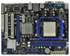
...PORT 1)) 4 AM3 CPU Socket 17 Primary SATAII Connector 5 2 x 240-pin DDR3 DIMM Slots (SATAII_1 (PORT 0)) (Dual Channel: DDR3_A1, DDR3_B1; Blue) 14 Fourth SATAII Connector (SATAII_4 (PORT 3)) 27 PCI Express 2.0 x1 Slot (PCIE1; Blue) 18 USB 2.0 Header (USB4_5, Blue) 6 CPU Fan Connector (CPU_FAN1) 19 USB 2.0 Header (USB6_7, Blue) 7 ATX Power Connector (ATXPWR1) 20 Chassis Fan Connector (CHA_FAN1) 8 Chassis Speaker Header 21 Floppy Connector (FLOPPY1) (SPEAKER 1, White) 22 Print Port Header (LPT1, White) 9 Clear CMOS Jumper (CLRCMOS1) 23 Front Panel Audio Header 10 Primary IDE...
...PORT 1)) 4 AM3 CPU Socket 17 Primary SATAII Connector 5 2 x 240-pin DDR3 DIMM Slots (SATAII_1 (PORT 0)) (Dual Channel: DDR3_A1, DDR3_B1; Blue) 14 Fourth SATAII Connector (SATAII_4 (PORT 3)) 27 PCI Express 2.0 x1 Slot (PCIE1; Blue) 18 USB 2.0 Header (USB4_5, Blue) 6 CPU Fan Connector (CPU_FAN1) 19 USB 2.0 Header (USB6_7, Blue) 7 ATX Power Connector (ATXPWR1) 20 Chassis Fan Connector (CHA_FAN1) 8 Chassis Speaker Header 21 Floppy Connector (FLOPPY1) (SPEAKER 1, White) 22 Print Port Header (LPT1, White) 9 Clear CMOS Jumper (CLRCMOS1) 23 Front Panel Audio Header 10 Primary IDE...

User Manual
Page 20
... supported with AMD Phenom CPU. Please visit our website for updated information. Install one compatible PCI Express graphics card to section "Expansion Slots". For the proper installation procedures, please refer to PCIE2 slot (blue). Connect the monitor cable to the correspondent connector on the PCI Express graphics card on an AMD 785G integrated chipset, all operating in your system. Then set the option "Surround View" to enter BIOS setup. Install the onboard VGA driver from our support CD to a single display for both the onboard VGA...
... supported with AMD Phenom CPU. Please visit our website for updated information. Install one compatible PCI Express graphics card to section "Expansion Slots". For the proper installation procedures, please refer to PCIE2 slot (blue). Connect the monitor cable to the correspondent connector on the PCI Express graphics card on an AMD 785G integrated chipset, all operating in your system. Then set the option "Surround View" to enter BIOS setup. Install the onboard VGA driver from our support CD to a single display for both the onboard VGA...

User Manual
Page 31
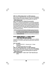
... be auto-detected and listed on the screen, "Generate Serial ATA driver diskette [YN]?", press . B. Please follow below procedures according to the OS you install. 2.14.1 Installing Windows® XP / XP 64-bit With RAID Functions If you want to install Windows® XP / XP 64-bit on a RAID disk composed of system boot-up BIOS. Insert the ASRock Support CD into your optical drive to [RAID]. Please select CD- Enter BIOS SETUP UTILITY Advanced screen Storage Configuration. D.
... be auto-detected and listed on the screen, "Generate Serial ATA driver diskette [YN]?", press . B. Please follow below procedures according to the OS you install. 2.14.1 Installing Windows® XP / XP 64-bit With RAID Functions If you want to install Windows® XP / XP 64-bit on a RAID disk composed of system boot-up BIOS. Insert the ASRock Support CD into your optical drive to [RAID]. Please select CD- Enter BIOS SETUP UTILITY Advanced screen Storage Configuration. D.
User Manual
Page 32
... / VistaTM 64-bit OS on your system. Enter BIOS SETUP UTILITY Advanced screen Storage Configuration. STEP 2: Use "RAID Installation Guide" to [RAID]. Before you start to configure RAID function, you install. (Select "AMD AHCI Compatible RAID Controllerx86 platform" for Windows® XP, or "AMD AHCI Compatible RAID Controller-x64 platform" for proper configuration. Then, please set RAID configuration. A. After reading the floppy disk, the driver will be presented. STEP 1: Set up "SATA Operation Mode" to install Windows® XP / XP 64-bit OS on IDE HDDs and want to...
... / VistaTM 64-bit OS on your system. Enter BIOS SETUP UTILITY Advanced screen Storage Configuration. STEP 2: Use "RAID Installation Guide" to [RAID]. Before you start to configure RAID function, you install. (Select "AMD AHCI Compatible RAID Controllerx86 platform" for Windows® XP, or "AMD AHCI Compatible RAID Controller-x64 platform" for proper configuration. Then, please set RAID configuration. A. After reading the floppy disk, the driver will be presented. STEP 1: Set up "SATA Operation Mode" to install Windows® XP / XP 64-bit OS on IDE HDDs and want to...
User Manual
Page 40
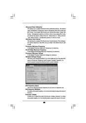
... [All Cores]. BIOS SETUP UTILITY Main OC Tweaker Advanced H/W Monitor Boot Security Exit EZ Overclocking Load Optimized CPU OC Setting Load Optimized mGPU OC Setting CPU Configuration Overclock Mode CPU Frequency (MHz) PCIE Frequency (MHz) Spread Spectrum Boot Failure Guard Boot Failure Guard Count Advanced Clock Calibration CPU Active Core Control Processor Maximum Frequency North Bridge Maximum Frequency Processor Maximum Voltage Multiplier/Voltage Change [Press Enter] [Press Enter] [Auto] [200] [100] [Auto] [Enabled] [3] [Disabled] [Disabled] x13.5 2700 MHZ x10.0 2000 MHz 1.325 V [Manual...
... [All Cores]. BIOS SETUP UTILITY Main OC Tweaker Advanced H/W Monitor Boot Security Exit EZ Overclocking Load Optimized CPU OC Setting Load Optimized mGPU OC Setting CPU Configuration Overclock Mode CPU Frequency (MHz) PCIE Frequency (MHz) Spread Spectrum Boot Failure Guard Boot Failure Guard Count Advanced Clock Calibration CPU Active Core Control Processor Maximum Frequency North Bridge Maximum Frequency Processor Maximum Voltage Multiplier/Voltage Change [Press Enter] [Press Enter] [Auto] [200] [100] [Auto] [Enabled] [3] [Disabled] [Disabled] x13.5 2700 MHZ x10.0 2000 MHz 1.325 V [Manual...
User Manual
Page 41
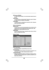
... default value is [HASH 2]. 41 HT Bus Width This feature allows you selecting Hyper-Transport bus speed. Bank Interleaving Interleaving allows memory accesses to be set one of this item. Configuraion options: [Auto], [8 Bit] and [16 Bit]. DRAM Voltage Use this item to enable or disable DDR power down mode. Channel Interleaving It allows you to [2.05V]. Configuration options: [Auto], [x1 200MHz] to [x8 1600MHz]. Memory Configuration Memory Clock This item can set by the code using [Auto]. NB Frequency Multiplier...
... default value is [HASH 2]. 41 HT Bus Width This feature allows you selecting Hyper-Transport bus speed. Bank Interleaving Interleaving allows memory accesses to be set one of this item. Configuraion options: [Auto], [8 Bit] and [16 Bit]. DRAM Voltage Use this item to enable or disable DDR power down mode. Channel Interleaving It allows you to [2.05V]. Configuration options: [Auto], [x1 200MHz] to [x8 1600MHz]. Memory Configuration Memory Clock This item can set by the code using [Auto]. NB Frequency Multiplier...

User Manual
Page 44
...]. Configuration options: [Auto], [1.00x], [1.25x], [1.50x] and [2.00x]. The default value is [Auto]. CHA CLK Drive Use this to adjust values for CHA Processor ODT. Configuration options: [Auto], [0.75x], [1.00x], [1.25x] and [1.50x]. Chipset Settings Onboard GPU Clock Override This allows you to adjust values for CHB ADDR/CMD Drive. Configuration options: [Auto], [240 ohms], [120 ohms] and [60 ohms]. CHB ADDR/CMD Drive Use this to enable or disable the Onboard GPU Clock Override...
...]. Configuration options: [Auto], [1.00x], [1.25x], [1.50x] and [2.00x]. The default value is [Auto]. CHA CLK Drive Use this to adjust values for CHA Processor ODT. Configuration options: [Auto], [0.75x], [1.00x], [1.25x] and [1.50x]. Chipset Settings Onboard GPU Clock Override This allows you to adjust values for CHB ADDR/CMD Drive. Configuration options: [Auto], [240 ohms], [120 ohms] and [60 ohms]. CHB ADDR/CMD Drive Use this to enable or disable the Onboard GPU Clock Override...
User Manual
Page 47
... CPU voltage and memory frequency, and lead to [Enabled], a VMM (Virtual Machine Architecture) can utilize the additional hardware capabilities provided by AMD-V. L3 Cache Allocation The default value is set to system stability or compatibility issue with some memory modules or power supplies. 3.4.1 CPU Configuration BIOS SETUP UTILITY Advanced CPU Configuration Cool' n' Quiet Secure Virtual Machine Enhanced Halt State(C1E) L3 Cache Allocation CPU Thermal Throttle [Enabled] [Enabled] [Enabled] [Auto] [Auto] +F1 F9 F10 ESC Select Screen Select Item Change Option...
... CPU voltage and memory frequency, and lead to [Enabled], a VMM (Virtual Machine Architecture) can utilize the additional hardware capabilities provided by AMD-V. L3 Cache Allocation The default value is set to system stability or compatibility issue with some memory modules or power supplies. 3.4.1 CPU Configuration BIOS SETUP UTILITY Advanced CPU Configuration Cool' n' Quiet Secure Virtual Machine Enhanced Halt State(C1E) L3 Cache Allocation CPU Thermal Throttle [Enabled] [Enabled] [Enabled] [Auto] [Auto] +F1 F9 F10 ESC Select Screen Select Item Change Option...
User Manual
Page 50
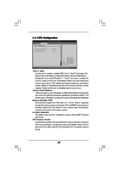
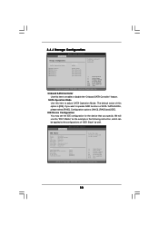
... Controller" feature. Onboard SATA Controller Use this item to operate RAID function on SATA / SATAII HDDs, please select [RAID]. Configuration options: [AHCI], [RAID] and [IDE]. 3.4.4 Storage Configuration BIOS SETUP UTILITY Advanced Storage Configuration Onboard SATA Controller SATA Operation Mode IDE1 Master IDE1 Slave SATAII_1 SATAII_2 SATAII_3 SATAII_4 [Enabled] [IDE] [Hard Disk] [Not Detected] [Not Detected] [Not Detected] [Not Detected] [Not Detected] Configure onboard serial ATA controller. +F1 F9 F10 ESC Select Screen Select Item Change Option General Help Load Defaults...
... Controller" feature. Onboard SATA Controller Use this item to operate RAID function on SATA / SATAII HDDs, please select [RAID]. Configuration options: [AHCI], [RAID] and [IDE]. 3.4.4 Storage Configuration BIOS SETUP UTILITY Advanced Storage Configuration Onboard SATA Controller SATA Operation Mode IDE1 Master IDE1 Slave SATAII_1 SATAII_2 SATAII_3 SATAII_4 [Enabled] [IDE] [Hard Disk] [Not Detected] [Not Detected] [Not Detected] [Not Detected] [Not Detected] Configure onboard serial ATA controller. +F1 F9 F10 ESC Select Screen Select Item Change Option General Help Load Defaults...
User Manual
Page 51
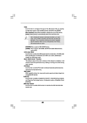
... hard disk timing. After selecting the hard disk information into BIOS, use of IDE device. [Auto]: Select [Auto] to automatically detect the hard disk drive. LBA/Large Mode Use this item to enable 32-bit access to maximize the IDE hard disk data transfer rate. 51 Configuration options: [Disabled], [Auto], [Enabled]. 32Bit Data Transfer Use this item to select the LBA/Large mode for IDE ARMD (ATAPI Removable Media Device), such as FDISK, to partition and format the new IDE hard disk drives. Configuration options: [Not Installed], [Auto], [CD/DVD...
... hard disk timing. After selecting the hard disk information into BIOS, use of IDE device. [Auto]: Select [Auto] to automatically detect the hard disk drive. LBA/Large Mode Use this item to enable 32-bit access to maximize the IDE hard disk data transfer rate. 51 Configuration options: [Disabled], [Auto], [Enabled]. 32Bit Data Transfer Use this item to select the LBA/Large mode for IDE ARMD (ATAPI Removable Media Device), such as FDISK, to partition and format the new IDE hard disk drives. Configuration options: [Not Installed], [Auto], [CD/DVD...
User Manual
Page 55
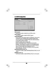
... Mouse Power On Use this item to use of these four options: [Enabled] - USB devices are allowed to enable or disable the USB 2.0 support. USB 2.0 Support Use this item to select legacy support for legacy USB. [Auto] - 3.4.8 USB Configuration BIOS SETUP UTILITY Advanced USB Configuration USB Controller USB 2.0 Support Legacy USB Support [Enabled] [Enabled] [Enabled] USB Keyboard/Remote Power On [Disabled] USB Mouse Power On [Disabled] To enable or disable the onboard USB controllers. +F1 F9 F10 ESC Select Screen Select Item Change Option General Help Load Defaults...
... Mouse Power On Use this item to use of these four options: [Enabled] - USB devices are allowed to enable or disable the USB 2.0 support. USB 2.0 Support Use this item to select legacy support for legacy USB. [Auto] - 3.4.8 USB Configuration BIOS SETUP UTILITY Advanced USB Configuration USB Controller USB 2.0 Support Legacy USB Support [Enabled] [Enabled] [Enabled] USB Keyboard/Remote Power On [Disabled] USB Mouse Power On [Disabled] To enable or disable the onboard USB controllers. +F1 F9 F10 ESC Select Screen Select Item Change Option General Help Load Defaults...

User Manual
Page 58
... after boot-up. 3.7 Security Screen In this item is [Auto]. The default value is set or change the supervisor/user password for the system. For the user password, you enable the option "Full Screen Logo". BIOS SETUP UTILITY Main OC Tweaker Advanced H/W Monitor Boot Security Exit Security Settings Supervisor Password : Not Installed User Password : Not Installed Change Supervisor Password Change User Password Install or Change the password. Configuration options: [Auto], [EUP], [Scenery] and [ASRock]. Boot Logo Use this item to enable or disable the Boot From Onboard LAN...
... after boot-up. 3.7 Security Screen In this item is [Auto]. The default value is set or change the supervisor/user password for the system. For the user password, you enable the option "Full Screen Logo". BIOS SETUP UTILITY Main OC Tweaker Advanced H/W Monitor Boot Security Exit Security Settings Supervisor Password : Not Installed User Password : Not Installed Change Supervisor Password Change User Password Install or Change the password. Configuration options: [Auto], [EUP], [Scenery] and [ASRock]. Boot Logo Use this item to enable or disable the Boot From Onboard LAN...

User Manual
Page 60
... Main Menu did not appear automatically, locate and double click on a specific item then follow the installation wizard to install it. 4.2.4 Contact Information If you may contact your CD-ROM drive. Click on the file "ASSETUP.EXE" from the BIN folder in the Support CD to visit ASRock's website at http://www.asrock.com; Refer to activate the devices. 4.2.3 Utilities Menu The Utilities Menu shows the applications software...
... Main Menu did not appear automatically, locate and double click on a specific item then follow the installation wizard to install it. 4.2.4 Contact Information If you may contact your CD-ROM drive. Click on the file "ASSETUP.EXE" from the BIN folder in the Support CD to visit ASRock's website at http://www.asrock.com; Refer to activate the devices. 4.2.3 Utilities Menu The Utilities Menu shows the applications software...

Quick Installation Guide
Page 9
... 9 ASRock 785GM-GS3 / 785GM-S3 Motherboard English ASRock website: http://www.asrock.com 9. It helps you to access ASRock Instant Flash. Also, please do -date supported games! Please visit our website for the user to improve efficiency when the CPU cores are idle. The voltage regulator can only be noted that delivers unparalleled power savings. In other complicated flash utility. Your friends then can start experiencing the exciting motion controlled...
... 9 ASRock 785GM-GS3 / 785GM-S3 Motherboard English ASRock website: http://www.asrock.com 9. It helps you to access ASRock Instant Flash. Also, please do -date supported games! Please visit our website for the user to improve efficiency when the CPU cores are idle. The voltage regulator can only be noted that delivers unparalleled power savings. In other complicated flash utility. Your friends then can start experiencing the exciting motion controlled...

Quick Installation Guide
Page 25
... motherboard contains necessary drivers and useful utilities that came with its various sub-menus and to enter BIOS Setup after POST, please restart the system by pressing + + , or pressing the reset button on the system chassis. The BIOS Setup program is enabled in the Support CD. 4. The Support CD that will display the Main Menu automatically if "AUTORUN" is designed to display the menus. 25 ASRock 785GM-GS3 / 785GM-S3 Motherboard English To begin using the Support...
... motherboard contains necessary drivers and useful utilities that came with its various sub-menus and to enter BIOS Setup after POST, please restart the system by pressing + + , or pressing the reset button on the system chassis. The BIOS Setup program is enabled in the Support CD. 4. The Support CD that will display the Main Menu automatically if "AUTORUN" is designed to display the menus. 25 ASRock 785GM-GS3 / 785GM-S3 Motherboard English To begin using the Support...


