

User Manual
Page 2
...device must accept any interference received, including interference that may apply, see www.dtsc.ca.gov/hazardouswaste/ perchlorate" ASRock Website: http://www.asrock.com Copyright Notice: No part of this documentation. When you discard the Lithium battery in California, USA, please... companies, and are furnished for a particular purpose. Version 1.0 Published April 2015 Copyright©2015 ASRock INC. Products and corporate names appearing in this motherboard contains Perchlorate, a toxic substance controlled in advance. CALIFORNIA, USA ONLY he Lithium battery adopted on...
...device must accept any interference received, including interference that may apply, see www.dtsc.ca.gov/hazardouswaste/ perchlorate" ASRock Website: http://www.asrock.com Copyright Notice: No part of this documentation. When you discard the Lithium battery in California, USA, please... companies, and are furnished for a particular purpose. Version 1.0 Published April 2015 Copyright©2015 ASRock INC. Products and corporate names appearing in this motherboard contains Perchlorate, a toxic substance controlled in advance. CALIFORNIA, USA ONLY he Lithium battery adopted on...

User Manual
Page 6
Contents Chapter 1 Introduction 1 1.1 Package Contents 1 1.2 Speciications 2 1.3 Motherboard Layout 6 1.4 I/O Panel 9 Chapter 2 Installation 11 2.1 Installing the CPU 12 2.2 Installing the CPU Fan and Heatsink 15 2.3 Installation of Memory Modules (DIMM) 16 2.4 Expansion Slots (PCI ...
Contents Chapter 1 Introduction 1 1.1 Package Contents 1 1.2 Speciications 2 1.3 Motherboard Layout 6 1.4 I/O Panel 9 Chapter 2 Installation 11 2.1 Installing the CPU 12 2.2 Installing the CPU Fan and Heatsink 15 2.3 Installation of Memory Modules (DIMM) 16 2.4 Expansion Slots (PCI ...

User Manual
Page 9
...; ASRock Fatal1ty X99X Killer Series/3.1 Motherboard (ATX Form Factor) • ASRock Fatal1ty X99X Killer Series/3.1 Quick Installation Guide • ASRock Fatal1ty X99X Killer Series/3.1 Support CD • 1 x I/O Panel Shield • 1 x ASRock USB 3.1 Card/A+A • 1 x ASRock SLI_Bridge_2S Card • 1 x ASRock 3-Way SLI-2S1S Bridge Card • 4 x Serial ATA (SATA) Data Cables (Optional) • 1 x HDD Saver Cable • 1 x Screw for Ultra M.2 Socket • 1 x Screw for purchasing ASRock Fatal1ty X99X Killer Series/3.1 motherboard, a reliable motherboard...
...; ASRock Fatal1ty X99X Killer Series/3.1 Motherboard (ATX Form Factor) • ASRock Fatal1ty X99X Killer Series/3.1 Quick Installation Guide • ASRock Fatal1ty X99X Killer Series/3.1 Support CD • 1 x I/O Panel Shield • 1 x ASRock USB 3.1 Card/A+A • 1 x ASRock SLI_Bridge_2S Card • 1 x ASRock 3-Way SLI-2S1S Bridge Card • 4 x Serial ATA (SATA) Data Cables (Optional) • 1 x HDD Saver Cable • 1 x Screw for Ultra M.2 Socket • 1 x Screw for purchasing ASRock Fatal1ty X99X Killer Series/3.1 motherboard, a reliable motherboard...

User Manual
Page 14
1.3 Motherboard Layout 12 3 4 56 7 USB 2.0 T: USB1 B: USB2 PS2 Keyboard /Mouse CLRC BTN1 USB 3.1 (Type-C) Vertical Type A USB CPU_FAN1 CPU_FAN2 ATX12V1 8 USB7 DDR4_D2 (64 bit, 288-pin .../Bass LINE IN Center: REAR SPK Bottom: Optical SPDIF 10 Top: Center: FRONT Bottom: MIC IN USB3_7_8 1 USB3_5_6 1 11 LAN 36 PWR_FAN1 PCIE_PWR1 35 Killer E2200 PCIE1 X99X Killer/3.1 Ultra M.2 PCIe Gen3 x4 SSATA3_2_3 SSATA3_0_1 CHA_FAN3 12 13 14 SATA3_0_3 M2 CT5 CT4 CT3 CT2 CT1 15 1 FATAL TY SATA3_1_4 PCIE2 CMOS Battery...
1.3 Motherboard Layout 12 3 4 56 7 USB 2.0 T: USB1 B: USB2 PS2 Keyboard /Mouse CLRC BTN1 USB 3.1 (Type-C) Vertical Type A USB CPU_FAN1 CPU_FAN2 ATX12V1 8 USB7 DDR4_D2 (64 bit, 288-pin .../Bass LINE IN Center: REAR SPK Bottom: Optical SPDIF 10 Top: Center: FRONT Bottom: MIC IN USB3_7_8 1 USB3_5_6 1 11 LAN 36 PWR_FAN1 PCIE_PWR1 35 Killer E2200 PCIE1 X99X Killer/3.1 Ultra M.2 PCIe Gen3 x4 SSATA3_2_3 SSATA3_0_1 CHA_FAN3 12 13 14 SATA3_0_3 M2 CT5 CT4 CT3 CT2 CT1 15 1 FATAL TY SATA3_1_4 PCIE2 CMOS Battery...

User Manual
Page 19
... the following precautions before installing or removing the motherboard components. Before you install motherboard components or change any components, place them on a carpet. Pre-installation Precautions Take note of your motherboard directly on a grounded anti-static pad or in the bag that the motherboard its into it. Fatal1ty X99X Killer/3.1 Series Chapter 2 Installation his is an ATX...
... the following precautions before installing or removing the motherboard components. Before you install motherboard components or change any components, place them on a carpet. Pre-installation Precautions Take note of your motherboard directly on a grounded anti-static pad or in the bag that the motherboard its into it. Fatal1ty X99X Killer/3.1 Series Chapter 2 Installation his is an ATX...

User Manual
Page 22
he cover must be placed if you wish to return the motherboard for ater service. 14 English 6 A B 7 A B 8 Please save and replace the cover if the processor is removed.
he cover must be placed if you wish to return the motherboard for ater service. 14 English 6 A B 7 A B 8 Please save and replace the cover if the processor is removed.

User Manual
Page 24
... Due to install identical (the same brand, speed, size and chip-type) DDR4 DIMM pairs. 2. 2.3 Installation of Memory Modules (DIMM) his motherboard provides eight 288-pin DDR4 (Double Data Rate 4) DIMM slots, and supports Quad Channel Memory Technology. 1. For quad channel coniguration, you force the... DIMM into a DDR4 slot; It will cause permanent damage to the motherboard and the DIMM if you always need to Intel® CPU spec deinition, please install the memory modules on DDR4_A1, DDR4_B1, DDR4_C1 ...
... Due to install identical (the same brand, speed, size and chip-type) DDR4 DIMM pairs. 2. 2.3 Installation of Memory Modules (DIMM) his motherboard provides eight 288-pin DDR4 (Double Data Rate 4) DIMM slots, and supports Quad Channel Memory Technology. 1. For quad channel coniguration, you force the... DIMM into a DDR4 slot; It will cause permanent damage to the motherboard and the DIMM if you always need to Intel® CPU spec deinition, please install the memory modules on DDR4_A1, DDR4_B1, DDR4_C1 ...
User Manual
Page 26
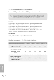
... used for PCI Express x1 lane width cards. 2.4 Expansion Slots (PCI Express Slots) here are 5 PCI Express slots and 1 mini-PCI Express slot on the motherboard. PCIe Slot Conigurations (For CPU with 40 PCIe lanes) Single Graphics Card PCIE1 x16 PCIE2 N/A PCIE3 N/A PCIE4 N/A PCIE5 N/A Two Graphics Cards in CrossFireXTM or SLITM...
... used for PCI Express x1 lane width cards. 2.4 Expansion Slots (PCI Express Slots) here are 5 PCI Express slots and 1 mini-PCI Express slot on the motherboard. PCIe Slot Conigurations (For CPU with 40 PCIe lanes) Single Graphics Card PCIE1 x16 PCIE2 N/A PCIE3 N/A PCIE4 N/A PCIE5 N/A Two Graphics Cards in CrossFireXTM or SLITM...
User Manual
Page 27
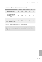
English 19 Fatal1ty X99X Killer/3.1 Series PCIe Slot Conigurations (For CPU with 28 PCIe lanes) PCIE1 PCIE2 PCIE3 PCIE4 PCIE5 Single Graphics Card x16 N/A N/A N/A N/A Two Graphics Cards in CrossFireXTM or SLITM Mode x16 N/A x8 N/A N/A hree Graphics Cards in 3-Way CrossFireXTM Mode x16 N/A x8 N/A x4 *3-Way SLITM Mode is not supported for CPU with 28 PCIe lanes. For a better thermal environment, please connect a chassis fan to the motherboard's chassis fan connector (CHA_FAN1, CHA_FAN2 or CHA_FAN3) when using multiple graphics cards.
English 19 Fatal1ty X99X Killer/3.1 Series PCIe Slot Conigurations (For CPU with 28 PCIe lanes) PCIE1 PCIE2 PCIE3 PCIE4 PCIE5 Single Graphics Card x16 N/A N/A N/A N/A Two Graphics Cards in CrossFireXTM or SLITM Mode x16 N/A x8 N/A N/A hree Graphics Cards in 3-Way CrossFireXTM Mode x16 N/A x8 N/A x4 *3-Way SLITM Mode is not supported for CPU with 28 PCIe lanes. For a better thermal environment, please connect a chassis fan to the motherboard's chassis fan connector (CHA_FAN1, CHA_FAN2 or CHA_FAN3) when using multiple graphics cards.

User Manual
Page 29
... S1/S3 sleep state. he LED is of (S5). he front panel design may conigure the way to the motherboard. he LED keeps blinking when the system is reading or writing data. Fatal1ty X99X Killer/3.1 Series 2.6 Onboard Headers and Connectors Onboard headers and connectors are matched correctly. HDLED (Hard Drive Activity LED): Connect to...
... S1/S3 sleep state. he LED is of (S5). he front panel design may conigure the way to the motherboard. he LED keeps blinking when the system is reading or writing data. Fatal1ty X99X Killer/3.1 Series 2.6 Onboard Headers and Connectors Onboard headers and connectors are matched correctly. HDLED (Hard Drive Activity LED): Connect to...
User Manual
Page 30
If the Ultra M.2 Socket has been occupied, the internal SSATA3_2 will not function. he SATA Express connector is shared with up to this motherboard. Serial ATA3 Connectors (SSATA3_0_1: see p.6, No. 13) (SSATA3_2_3: see p.6, No. 14) (SATA3_0_3: see p.6, No. 15) (SATA3_1_4: see p.6, No. 16) (SATA3_2_5: see p.6, No. 8) 22 SATAE_1 SATA3_5 ...
If the Ultra M.2 Socket has been occupied, the internal SSATA3_2 will not function. he SATA Express connector is shared with up to this motherboard. Serial ATA3 Connectors (SSATA3_0_1: see p.6, No. 13) (SSATA3_2_3: see p.6, No. 14) (SATA3_0_3: see p.6, No. 15) (SATA3_1_4: see p.6, No. 16) (SATA3_2_5: see p.6, No. 8) 22 SATAE_1 SATA3_5 ...

User Manual
Page 31
... this motherboard. C. Chassis and Power Fan Connectors (4-pin CHA_FAN1) (see p.6, No. 26) (3-pin CHA_FAN2) (see p.6, No. 25) GND +12V CHA_FAN_SPEED FAN_SPEED_CONTROL CHA_FAN_SPEED FAN_VOLTAGE GND Please connect fan cables to the fan connectors and match the black wire to OUT2_L. Connect Audio_R (RIN) to OUT2_R and Audio_L (LIN) to the ground pin. Fatal1ty X99X Killer...
... this motherboard. C. Chassis and Power Fan Connectors (4-pin CHA_FAN1) (see p.6, No. 26) (3-pin CHA_FAN2) (see p.6, No. 25) GND +12V CHA_FAN_SPEED FAN_SPEED_CONTROL CHA_FAN_SPEED FAN_VOLTAGE GND Please connect fan cables to the fan connectors and match the black wire to OUT2_L. Connect Audio_R (RIN) to OUT2_R and Audio_L (LIN) to the ground pin. Fatal1ty X99X Killer...

User Manual
Page 32
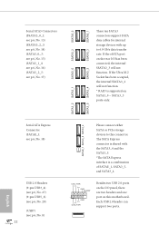
...p.6, No. 3) 1 13 8 5 4 1 PCIe Power Connector (4-pin PCIE_PWR1) (see p.6, No. 6) 4 3 21 GND +12V CPU_FAN_SPEED FAN_SPEED_CONTROL GND FAN_VOLTAGE CPU_FAN_SPEED his motherboard provides a 24-pin ATX power connector. To use a 4-pin ATX power supply, please plug it along Pin 1 and Pin 5. To use a 20-pin ATX power...) (see p.6, No. 36) GND FAN_VOLTAGE CHA_FAN_SPEED CPU Fan Connectors (4-pin CPU_FAN1) (see p.6, No. 4) (3-pin CPU_FAN2) (see p.6, No. 35) his motherboard provides a 4-Pin CPU fan (Quiet Fan) connector. his motherboard provides an 8-pin ATX 12V power connector.
...p.6, No. 3) 1 13 8 5 4 1 PCIe Power Connector (4-pin PCIE_PWR1) (see p.6, No. 6) 4 3 21 GND +12V CPU_FAN_SPEED FAN_SPEED_CONTROL GND FAN_VOLTAGE CPU_FAN_SPEED his motherboard provides a 24-pin ATX power connector. To use a 4-pin ATX power supply, please plug it along Pin 1 and Pin 5. To use a 20-pin ATX power...) (see p.6, No. 36) GND FAN_VOLTAGE CHA_FAN_SPEED CPU Fan Connectors (4-pin CPU_FAN1) (see p.6, No. 4) (3-pin CPU_FAN2) (see p.6, No. 35) his motherboard provides a 4-Pin CPU fan (Quiet Fan) connector. his motherboard provides an 8-pin ATX 12V power connector.
User Manual
Page 34
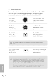
...and stability of your system. Users may refer to the BIOS LEDs (BIOS_A_LED or BIOS_B_LED) to ensure normal system operation. 2.7 Smart Switches he motherboard has four smart switches: Power Switch, Reset Switch, Clear CMOS Switch and one BIOS Selection Switch, allowing users to quickly turn on/of ... quickly turn on/of the system. his function is workable only when you power of your computer and unplug the power supply. English 26 his motherboard has two BIOS chips, a primary BIOS (BIOS_A) and a backup BIOS (BIOS_ B), which BIOS is corrupted or damaged, just lip the BIOS...
...and stability of your system. Users may refer to the BIOS LEDs (BIOS_A_LED or BIOS_B_LED) to ensure normal system operation. 2.7 Smart Switches he motherboard has four smart switches: Power Switch, Reset Switch, Clear CMOS Switch and one BIOS Selection Switch, allowing users to quickly turn on/of ... quickly turn on/of the system. his function is workable only when you power of your computer and unplug the power supply. English 26 his motherboard has two BIOS chips, a primary BIOS (BIOS_A) and a backup BIOS (BIOS_ B), which BIOS is corrupted or damaged, just lip the BIOS...

User Manual
Page 37
... identical PCI Express x16 graphics cards. It is not supported. Step 2 If required, connect the auxiliary power source to PCIE3 slot. Fatal1ty X99X Killer/3.1 Series 2.9 SLITM , 3-Way SLITMand Quad SLITM Operation Guide his motherboard supports NVIDIA® SLITM , 3-Way SLITM and Quad SLITM (Scalable Link Interface) technology that are properly seated on the slots...
... identical PCI Express x16 graphics cards. It is not supported. Step 2 If required, connect the auxiliary power source to PCIE3 slot. Fatal1ty X99X Killer/3.1 Series 2.9 SLITM , 3-Way SLITMand Quad SLITM Operation Guide his motherboard supports NVIDIA® SLITM , 3-Way SLITM and Quad SLITM (Scalable Link Interface) technology that are properly seated on the slots...
User Manual
Page 42
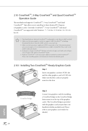
...sure that your graphics card driver supports AMD CrossFireXTM technology. If you pair a 12-pipe CrossFireXTM Edition card with this motherboard. Diferent CrossFireXTM cards may require diferent methods to PCIE3 slot. You should only use a AMD certiied PSU. CrossFire Bridge...-bit / 8 / 8 64-bit / 8.1 / 8.1 64bit OS. 1. 2.10 CrossFireXTM, 3-Way CrossFireXTM and Quad CrossFireXTM Operation Guide his motherboard supports CrossFireXTM, 3-way CrossFireXTM and Quad CrossFireXTM that allows you to install up to use identical CrossFireXTM-ready graphics cards that are AMD certiied. 2....
...sure that your graphics card driver supports AMD CrossFireXTM technology. If you pair a 12-pipe CrossFireXTM Edition card with this motherboard. Diferent CrossFireXTM cards may require diferent methods to PCIE3 slot. You should only use a AMD certiied PSU. CrossFire Bridge...-bit / 8 / 8 64-bit / 8.1 / 8.1 64bit OS. 1. 2.10 CrossFireXTM, 3-Way CrossFireXTM and Quad CrossFireXTM Operation Guide his motherboard supports CrossFireXTM, 3-way CrossFireXTM and Quad CrossFireXTM that allows you to install up to use identical CrossFireXTM-ready graphics cards that are AMD certiied. 2....

User Manual
Page 44
Make sure that is provided with the graphics card you purchase, not bundled with this motherboard. English 36 2.10.2 Installing Three CrossFireXTM-Ready Graphics Cards Step 1 Insert one CrossFire Bridge to connect the graphics cards on PCIE1 and PCIE3 slots, and ...
Make sure that is provided with the graphics card you purchase, not bundled with this motherboard. English 36 2.10.2 Installing Three CrossFireXTM-Ready Graphics Cards Step 1 Insert one CrossFire Bridge to connect the graphics cards on PCIE1 and PCIE3 slots, and ...
User Manual
Page 47
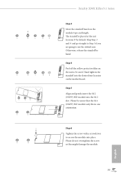
... location on the module type and length. Please do not overtighten the screw as this might damage the module. E D C B A E D C B A C B A E D C B A E D NUT2 NUT1 Fatal1ty X99X Killer/3.1 Series Step 3 Move the standof based on the motherboard. Skip Step 3 and 4 and go straight to Step 5 if you are going to be aware that the M.2 (NGFF) SSD module only...
... location on the module type and length. Please do not overtighten the screw as this might damage the module. E D C B A E D C B A C B A E D C B A E D NUT2 NUT1 Fatal1ty X99X Killer/3.1 Series Step 3 Move the standof based on the motherboard. Skip Step 3 and 4 and go straight to Step 5 if you are going to be aware that the M.2 (NGFF) SSD module only...

User Manual
Page 49
... coniguration, please refer to the section 3.2 "F-Stream" in this motherboard allows you to two SATA HDDs. 2. Connection Diagram 1 HDD Saver Cable 2 SATA data cable *he HDD Saver Connector supports up to switch on and off the connected HDDs via sotware when needed. Fatal1ty X99X Killer/3.1 Series 2.12 HDD Saver Cable Installation Guide The HDD...
... coniguration, please refer to the section 3.2 "F-Stream" in this motherboard allows you to two SATA HDDs. 2. Connection Diagram 1 HDD Saver Cable 2 SATA data cable *he HDD Saver Connector supports up to switch on and off the connected HDDs via sotware when needed. Fatal1ty X99X Killer/3.1 Series 2.12 HDD Saver Cable Installation Guide The HDD...

User Manual
Page 51
...Fatal1ty X99X Killer/3.1 Series Installation Procedure he ASRock USB 3.1 Card/A+A provides two external USB 3.1 ports which support transfer rates up to or lower than the standard 0.9 Amps, we suggest following this step to the documentation that were disconnected. 43 English Step 1 Power of your motherboard... and remove its slot bracket. *To maximize the performance of ASRock USB 3.1/A+A, it is occupied, insert the card into the PCIE3 (from the computer case. *...
...Fatal1ty X99X Killer/3.1 Series Installation Procedure he ASRock USB 3.1 Card/A+A provides two external USB 3.1 ports which support transfer rates up to or lower than the standard 0.9 Amps, we suggest following this step to the documentation that were disconnected. 43 English Step 1 Power of your motherboard... and remove its slot bracket. *To maximize the performance of ASRock USB 3.1/A+A, it is occupied, insert the card into the PCIE3 (from the computer case. *...

