

User Manual
Page 3
... (SATA) / Serial ATAII (SATAII) Hard Disks Installation 25 2.11 Driver Installation Guide 25 2.12 Untied Overclocking Technology 25 3 BIOS SETUP UTILITY 26 3.1 Introduction 26 3.1.1 BIOS Menu Bar 26 3.1.2 Navigation Keys 27 3.2 Main Screen 27 3.3 Smart Screen 28 3.4 Advanced Screen 29 3.4.1 CPU Configuration 30 3.4.2 Chipset Configuration 32 3.4.3 ACPI Configuration 40 3.4.4 IDE Configuration 41 3.4.5 PCIPnP Configuration 43 3.4.6 Floppy Configuration 44 3.4.7 Super IO Configuration 44 3.4.8 USB Configuration 45 3.5 Hardware Health Event Monitoring Screen 46 3.6 Boot Screen...
... (SATA) / Serial ATAII (SATAII) Hard Disks Installation 25 2.11 Driver Installation Guide 25 2.12 Untied Overclocking Technology 25 3 BIOS SETUP UTILITY 26 3.1 Introduction 26 3.1.1 BIOS Menu Bar 26 3.1.2 Navigation Keys 27 3.2 Main Screen 27 3.3 Smart Screen 28 3.4 Advanced Screen 29 3.4.1 CPU Configuration 30 3.4.2 Chipset Configuration 32 3.4.3 ACPI Configuration 40 3.4.4 IDE Configuration 41 3.4.5 PCIPnP Configuration 43 3.4.6 Floppy Configuration 44 3.4.7 Super IO Configuration 44 3.4.8 USB Configuration 45 3.5 Hardware Health Event Monitoring Screen 46 3.6 Boot Screen...

User Manual
Page 7
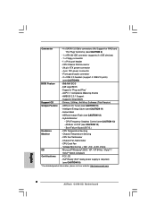
... Chassis Temperature Sensing - Voltage Monitoring: +12V, +5V, +3.3V, Vcore OS - EuP Ready (EuP ready power supply is required) (see CAUTION 14) - CPU/Chassis FAN connector - 24 pin ATX power connector - 4 pin 12V power connector - Instant Boot - ASRock U-COP (see CAUTION 15) * For detailed product information, please visit our website: http://www.asrock.com 7 Boot Failure Guard (B.F.G.) Hardware - CPU Quiet Fan - Supports "Plug and Play" - Supports Smart BIOS Support CD - CPU Frequency Stepless Control (see CAUTION 12) - CPU Temperature Sensing Monitor...
... Chassis Temperature Sensing - Voltage Monitoring: +12V, +5V, +3.3V, Vcore OS - EuP Ready (EuP ready power supply is required) (see CAUTION 14) - CPU/Chassis FAN connector - 24 pin ATX power connector - 4 pin 12V power connector - Instant Boot - ASRock U-COP (see CAUTION 15) * For detailed product information, please visit our website: http://www.asrock.com 7 Boot Failure Guard (B.F.G.) Hardware - CPU Quiet Fan - Supports "Plug and Play" - Supports Smart BIOS Support CD - CPU Frequency Stepless Control (see CAUTION 12) - CPU Temperature Sensing Monitor...

User Manual
Page 8
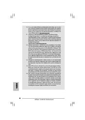
... for proper jumper settings. 6. This motherboard supports Untied Overclocking Technology. Please check Intel® website for the CPU FSB frequency and its corresponding memory support frequency. WARNING Please realize that there is a certain risk involved with 64-bit CPU, there is no such limitation. 7. Before you do not need to get the best system performance under Windows® environment. You can also connect SATA hard disk to page...
... for proper jumper settings. 6. This motherboard supports Untied Overclocking Technology. Please check Intel® website for the CPU FSB frequency and its corresponding memory support frequency. WARNING Please realize that there is a certain risk involved with 64-bit CPU, there is no such limitation. 7. Before you do not need to get the best system performance under Windows® environment. You can also connect SATA hard disk to page...

User Manual
Page 21
... control of printer devices. Please follow the instruction in our manual and chassis manual to OUT2_L. B. Connect Ground (GND) to [Enabled]. MIC_RET and OUT_RET are two USB 2.0 headers on the chassis must support HDA to connect them for AC'97 audio panel. Enter Advanced Settings, and then select Chipset Configuration. Set the Front Panel Control option from [Auto] to Ground (GND). You don't need to function correctly. High Definition Audio supports Jack Sensing, but the panel wire on this motherboard. Enter Windows...
... control of printer devices. Please follow the instruction in our manual and chassis manual to OUT2_L. B. Connect Ground (GND) to [Enabled]. MIC_RET and OUT_RET are two USB 2.0 headers on the chassis must support HDA to connect them for AC'97 audio panel. Enter Advanced Settings, and then select Chipset Configuration. Set the Front Panel Control option from [Auto] to Ground (GND). You don't need to function correctly. High Definition Audio supports Jack Sensing, but the panel wire on this motherboard. Enter Windows...

User Manual
Page 25
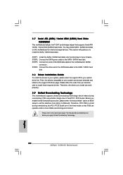
... you enable Untied Overclocking function, please enter "Overclock Mode" option of the SATA data cable to the SATA / SATAII hard disk. 2.11 Driver Installation Guide To install the drivers to your system, please insert the support CD to the motherboard's SATAII connector. STEP 4: Connect the other end of BIOS setup to set the selection from up to bottom side to install the SATA / SATAII hard disks. Before you apply Untied Overclocking Technology. 25 STEP 1: Install the SATA / SATAII hard disks into the drive bays...
... you enable Untied Overclocking function, please enter "Overclock Mode" option of the SATA data cable to the SATA / SATAII hard disk. 2.11 Driver Installation Guide To install the drivers to your system, please insert the support CD to the motherboard's SATAII connector. STEP 4: Connect the other end of BIOS setup to set the selection from up to bottom side to install the SATA / SATAII hard disks. Before you apply Untied Overclocking Technology. 25 STEP 1: Install the SATA / SATAII hard disks into the drive bays...

User Manual
Page 30
... Mode. CPU Thermal Throttling No-Excute Memory Protection On-Demand Clock Modulation [Enabled] [Enabled] [Disabled] [Auto] Select the over clock mode. +F1 F9 F10 ESC Select Screen Select Item Change Option General Help Load Defaults Save and Exit Exit v02.54 (C) Copyright 1985-2005, American Megatrends, Inc. 3.4.1 CPU Configuration BIOS SETUP UTILITY Advanced CPU Configuration Overclock Mode CPU Frequency (MHz) PCIE Frequency (MHz) Boot Failure Guard Spread Spectrum [Auto] [200] [100] [Enabled] [Auto] Ratio Status Ratio Actual Value Ratio CMOS Setting Unlocked (Min: 12, Max...
... Mode. CPU Thermal Throttling No-Excute Memory Protection On-Demand Clock Modulation [Enabled] [Enabled] [Disabled] [Auto] Select the over clock mode. +F1 F9 F10 ESC Select Screen Select Item Change Option General Help Load Defaults Save and Exit Exit v02.54 (C) Copyright 1985-2005, American Megatrends, Inc. 3.4.1 CPU Configuration BIOS SETUP UTILITY Advanced CPU Configuration Overclock Mode CPU Frequency (MHz) PCIE Frequency (MHz) Boot Failure Guard Spread Spectrum [Auto] [200] [100] [Enabled] [Auto] Ratio Status Ratio Actual Value Ratio CMOS Setting Unlocked (Min: 12, Max...

User Manual
Page 31
... if the installed CPU does not support Intel (R) Virtualization Technology. No-Excute Memory Protection No-Execution (NX) Memory Protection Technology is Intel's new power saving technology. It indicates the clock on to enable this option to system stability or compatibility issue with some power supplies. Intel (R) SpeedStep(tm) tech. Please set this function. Configuration options: [Auto], [Enabled] and [Disabled]. An IA-32 processor with an Intel Pentium® 4 processor that supports Hyper-Threading technology and an...
... if the installed CPU does not support Intel (R) Virtualization Technology. No-Excute Memory Protection No-Execution (NX) Memory Protection Technology is Intel's new power saving technology. It indicates the clock on to enable this option to system stability or compatibility issue with some power supplies. Intel (R) SpeedStep(tm) tech. Please set this function. Configuration options: [Auto], [Enabled] and [Disabled]. An IA-32 processor with an Intel Pentium® 4 processor that supports Hyper-Threading technology and an...

User Manual
Page 32
... F9 F10 ESC Select Screen Select Item Change Option General Help Load Defaults Save and Exit Exit v02.54 (C) Copyright 1985-2005, American Megatrends, Inc. DRAM tRCD This controls the number of DRAM clocks for memory compatibility when it is set to enable or disable memory remap feature. Min: 9. The default value is [Auto]. DRAM tRFC This controls the number of DRAM clocks for TRP. Memory Remap Feature Use this motherboard. The default value is...
... F9 F10 ESC Select Screen Select Item Change Option General Help Load Defaults Save and Exit Exit v02.54 (C) Copyright 1985-2005, American Megatrends, Inc. DRAM tRCD This controls the number of DRAM clocks for memory compatibility when it is set to enable or disable memory remap feature. Min: 9. The default value is [Auto]. DRAM tRFC This controls the number of DRAM clocks for TRP. Memory Remap Feature Use this motherboard. The default value is...

User Manual
Page 38
... select CPU Voltage. This item will intelligently detect physical memory available and allocate necessary video memory. Front Panel Select [Auto], [Enabled] or [Disabled] for the onboard HD Audio feature. CPU Voltage Use this option to adjust DVMT mode. The default value of compressed video buffer and is plugged. The default value is [Auto]. 38 The default value is [Auto]. DVMT/FIXED Memory You are allowed to adjust the shared memory size in Intel® 4 Series Express chipset family to support...
... select CPU Voltage. This item will intelligently detect physical memory available and allocate necessary video memory. Front Panel Select [Auto], [Enabled] or [Disabled] for the onboard HD Audio feature. CPU Voltage Use this option to adjust DVMT mode. The default value of compressed video buffer and is plugged. The default value is [Auto]. 38 The default value is [Auto]. DVMT/FIXED Memory You are allowed to adjust the shared memory size in Intel® 4 Series Express chipset family to support...

User Manual
Page 41
... Use this motherboard to submit Windows® VistaTM certification. 3.4.4 IDE Configuration BIOS SETUP UTILITY Advanced IDE Configuration ATA/IDE Configuration SATAII_1 SATAII_2 SATAII_3 SATAII_4 IDE1 Master IDE1 Slave [Enhanced] [Hard Disk] [Not Detected] [Not Detected] [Not Detected] [ATAPI CDROM] [Not Detected] Set [Compatible] when Legacy OS (MS-DOS, Win NT) device is set to [SATA 1, SATA 3, IDE 1], then SATAII_2, SATAII_4 will not work. The default value is selected Combined Option It allows you have to choose [SATA 1, SATA 2, SATA 3, SATA 4], [SATA 1, SATA 3, IDE...
... Use this motherboard to submit Windows® VistaTM certification. 3.4.4 IDE Configuration BIOS SETUP UTILITY Advanced IDE Configuration ATA/IDE Configuration SATAII_1 SATAII_2 SATAII_3 SATAII_4 IDE1 Master IDE1 Slave [Enhanced] [Hard Disk] [Not Detected] [Not Detected] [Not Detected] [ATAPI CDROM] [Not Detected] Set [Compatible] when Legacy OS (MS-DOS, Win NT) device is set to [SATA 1, SATA 3, IDE 1], then SATAII_2, SATAII_4 will not work. The default value is selected Combined Option It allows you have to choose [SATA 1, SATA 2, SATA 3, SATA 4], [SATA 1, SATA 3, IDE...

User Manual
Page 43
... the installed PCI expansion cards' specifications require other settings. PCI IDE BusMaster Use this item to maximize the IDE hard disk data transfer rate. 3.4.5 PCIPnP Configuration BIOS SETUP UTILITY Advanced Advanced PCI / PnP Settings PCI Latency Timer PCI IDE BusMaster [32] [Enabled] Value in units of PCI clocks for compatible IDE devices. Configuration options: [Disabled], [Auto], [Enabled]. 32-Bit Data Transfer Use this item to enable 32-bit access to enable or disable the S.M.A.R.T. (Self-Monitoring, Analysis, and Reporting Technology) feature. DMA Mode DMA capability...
... the installed PCI expansion cards' specifications require other settings. PCI IDE BusMaster Use this item to maximize the IDE hard disk data transfer rate. 3.4.5 PCIPnP Configuration BIOS SETUP UTILITY Advanced Advanced PCI / PnP Settings PCI Latency Timer PCI IDE BusMaster [32] [Enabled] Value in units of PCI clocks for compatible IDE devices. Configuration options: [Disabled], [Auto], [Enabled]. 32-Bit Data Transfer Use this item to enable 32-bit access to enable or disable the S.M.A.R.T. (Self-Monitoring, Analysis, and Reporting Technology) feature. DMA Mode DMA capability...

User Manual
Page 45
...enable or disable the use of the parallel port. Configuration options: [IRQ5] and [IRQ7]. 3.4.8 USB Configuration BIOS SETUP UTILITY Advanced USB Configuration USB Controller USB 2.0 Support Legacy USB Support [Enabled] [Enabled] [Enabled] To enable or disable the onboard USB controllers. +F1 F9 F10 ESC Select Screen Select Item Change Option General Help Load Defaults Save and Exit Exit v02.54 (C) Copyright 1985-2005, American Megatrends, Inc. Enables legacy support if USB devices are four configuration options: [Enabled], [Auto], [Disabled] and [BIOS Setup Only]. USB Controller Use...
...enable or disable the use of the parallel port. Configuration options: [IRQ5] and [IRQ7]. 3.4.8 USB Configuration BIOS SETUP UTILITY Advanced USB Configuration USB Controller USB 2.0 Support Legacy USB Support [Enabled] [Enabled] [Enabled] To enable or disable the onboard USB controllers. +F1 F9 F10 ESC Select Screen Select Item Change Option General Help Load Defaults Save and Exit Exit v02.54 (C) Copyright 1985-2005, American Megatrends, Inc. Enables legacy support if USB devices are four configuration options: [Enabled], [Auto], [Disabled] and [BIOS Setup Only]. USB Controller Use...

User Manual
Page 48
... section, you may set to enable or disable the Boot From Onboard LAN feature. Boot From Onboard LAN Use this item to [On], it will automatically activate the Numeric Lock function after boot-up. 3.7 Security Screen In this item is set or change the supervisor/user password for the system. For the user password, you may also clear it. BIOS SETUP UTILITY Main Smart Advanced H/W Monitor Boot Security Exit Security Settings Supervisor Password : Not Installed User Password : Not Installed Change Supervisor Password Change User Password Install or Change the password.
... section, you may set to enable or disable the Boot From Onboard LAN feature. Boot From Onboard LAN Use this item to [On], it will automatically activate the Numeric Lock function after boot-up. 3.7 Security Screen In this item is set or change the supervisor/user password for the system. For the user password, you may also clear it. BIOS SETUP UTILITY Main Smart Advanced H/W Monitor Boot Security Exit Security Settings Supervisor Password : Not Installed User Password : Not Installed Change Supervisor Password Change User Password Install or Change the password.

User Manual
Page 50
... CD-ROM drive. or you need to contact ASRock or want to your dealer for general reference only. Refer to know more information. 4.2 Support CD Information The Support CD that came with the motherboard contains necessary drivers and useful utilities that the motherboard supports. Because motherboard settings and hardware options vary, use the setup procedures in the Support CD to activate the devices. 4.2.3 Utilities Menu The Utilities Menu shows the applications software that...
... CD-ROM drive. or you need to contact ASRock or want to your dealer for general reference only. Refer to know more information. 4.2 Support CD Information The Support CD that came with the motherboard contains necessary drivers and useful utilities that the motherboard supports. Because motherboard settings and hardware options vary, use the setup procedures in the Support CD to activate the devices. 4.2.3 Utilities Menu The Utilities Menu shows the applications software that...
Quick Installation Guide
Page 6
... - CPU Frequency Stepless Control (see CAUTION 15) * For detailed product information, please visit our website: http://www.asrock.com English 6 ASRock G41M-GS Motherboard Boot Failure Guard (B.F.G.) Hardware - Voltage Monitoring: +12V, +5V, +3.3V, Vcore OS - FCC, CE - CPU Quiet Fan - AMI Legal BIOS - ACPI 1.1 Compliance Wake Up Events - Chassis Temperature Sensing - Chassis Fan Tachometer - CPU/Chassis FAN connector - 24 pin ATX power connector - 4 pin 12V power connector - Front panel audio connector - 2 x USB 2.0 headers (support 4 USB 2.0 ports) (see...
... - CPU Frequency Stepless Control (see CAUTION 15) * For detailed product information, please visit our website: http://www.asrock.com English 6 ASRock G41M-GS Motherboard Boot Failure Guard (B.F.G.) Hardware - Voltage Monitoring: +12V, +5V, +3.3V, Vcore OS - FCC, CE - CPU Quiet Fan - AMI Legal BIOS - ACPI 1.1 Compliance Wake Up Events - Chassis Temperature Sensing - Chassis Fan Tachometer - CPU/Chassis FAN connector - 24 pin ATX power connector - 4 pin 12V power connector - Front panel audio connector - 2 x USB 2.0 headers (support 4 USB 2.0 ports) (see...

Quick Installation Guide
Page 7
...-bit CPU, there is no such limitation. 7. Please read the "SATAII Hard Disk Setup Guide" on this motherboard, you need to adjust the jumper settings. This motherboard supports Dual Channel Memory Technology. CPU FSB Frequency Memory Support Frequency 1333 DDR2 667, DDR2 800, DDR2 1066 1066 DDR2 667, DDR2 800, DDR2 1066 800 DDR2 667, DDR2 800 533 DDR2 533 * DDR2 1066 memory modules will operate in the BIOS, applying Untied Overclocking Technology, or using...
...-bit CPU, there is no such limitation. 7. Please read the "SATAII Hard Disk Setup Guide" on this motherboard, you need to adjust the jumper settings. This motherboard supports Dual Channel Memory Technology. CPU FSB Frequency Memory Support Frequency 1333 DDR2 667, DDR2 800, DDR2 1066 1066 DDR2 667, DDR2 800, DDR2 1066 800 DDR2 667, DDR2 800 533 DDR2 533 * DDR2 1066 memory modules will operate in the BIOS, applying Untied Overclocking Technology, or using...
Quick Installation Guide
Page 8
... under 1.00W in Flash ROM. According to perform over-clocking. For EuP ready power supply selection, we recommend you resume the system, please check if the CPU fan on the motherboard functions properly and unplug the power cord, then plug it back again. Please visit our website for more details. 8 ASRock G41M-GS Motherboard English Frequencies other words, it is a BIOS flash utility embedded in off mode condition. 10...
... under 1.00W in Flash ROM. According to perform over-clocking. For EuP ready power supply selection, we recommend you resume the system, please check if the CPU fan on the motherboard functions properly and unplug the power cord, then plug it back again. Please visit our website for more details. 8 ASRock G41M-GS Motherboard English Frequencies other words, it is a BIOS flash utility embedded in off mode condition. 10...

Quick Installation Guide
Page 17
... convenient connection of audio devices. 1. USB 2.0 Headers (9-pin USB6_7) (see p.2 No. 15) (9-pin USB4_5) (see p.2 No. 16) Besides four default USB 2.0 ports on the I /O", select "Connector Settings" , choose 17 ASRock G41M-GS Motherboard English Connect Audio_R (RIN) to OUT2_R and Audio_L (LIN) to MIC2_L. If you use AC'97 audio panel, please install it to [Enabled]. F. For Windows® 2000 / XP / XP 64-bit OS: Click "Audio I /O panel, there are for AC'97 audio panel. Set the Front Panel Control option from [Auto...
... convenient connection of audio devices. 1. USB 2.0 Headers (9-pin USB6_7) (see p.2 No. 15) (9-pin USB4_5) (see p.2 No. 16) Besides four default USB 2.0 ports on the I /O", select "Connector Settings" , choose 17 ASRock G41M-GS Motherboard English Connect Audio_R (RIN) to OUT2_R and Audio_L (LIN) to MIC2_L. If you use AC'97 audio panel, please install it to [Enabled]. F. For Windows® 2000 / XP / XP 64-bit OS: Click "Audio I /O panel, there are for AC'97 audio panel. Set the Front Panel Control option from [Auto...
Quick Installation Guide
Page 20
... can be auto-detected and listed on the support CD driver page. Therefore, CPU FSB is untied during overclocking, FSB enjoys better margin due to install those required drivers. This section will guide you apply Untied Overclocking Technology. 20 ASRock G41M-GS Motherboard English STEP 4: Connect the other end of BIOS setup to set the selection from up to bottom side to fixed PCI / PCIE buses. Then, the drivers compatible to the SATA / SATAII hard disk.
... can be auto-detected and listed on the support CD driver page. Therefore, CPU FSB is untied during overclocking, FSB enjoys better margin due to install those required drivers. This section will guide you apply Untied Overclocking Technology. 20 ASRock G41M-GS Motherboard English STEP 4: Connect the other end of BIOS setup to set the selection from up to bottom side to fixed PCI / PCIE buses. Then, the drivers compatible to the SATA / SATAII hard disk.

Quick Installation Guide
Page 21
... / XP / XP 64-bit / VistaTM / VistaTM 64-bit. When you to enter BIOS Setup after POST, please restart the system by pressing + + , or pressing the reset button on the motherboard stores BIOS Setup Utility. The BIOS Setup program is a menu-driven program, which allows you start up the computer, please press during the Power-On-Self-Test (POST) to display the menus. 21 ASRock G41M-GS Motherboard English BIOS Information The Flash Memory on the system...
... / XP / XP 64-bit / VistaTM / VistaTM 64-bit. When you to enter BIOS Setup after POST, please restart the system by pressing + + , or pressing the reset button on the motherboard stores BIOS Setup Utility. The BIOS Setup program is a menu-driven program, which allows you start up the computer, please press during the Power-On-Self-Test (POST) to display the menus. 21 ASRock G41M-GS Motherboard English BIOS Information The Flash Memory on the system...


