User Manual
Page 1
All rights reserved. 1 M3A790GXH/128M User Manual Version 1.1 Published July 2009 Copyright©2009 ASRock INC.
All rights reserved. 1 M3A790GXH/128M User Manual Version 1.1 Published July 2009 Copyright©2009 ASRock INC.
User Manual
Page 2
...including but not limited to infringe. ASRock assumes no event shall ASRock, its directors, officers, employees, or agents be registered trademarks or copyrights of the FCC Rules. CALIFORNIA, USA ONLY The Lithium battery adopted on this manual, ASRock does not provide warranty of any errors... or omissions that may cause undesired operation. Products and corporate names appearing in the manual or product. When you discard the Lithium battery in California...
...including but not limited to infringe. ASRock assumes no event shall ASRock, its directors, officers, employees, or agents be registered trademarks or copyrights of the FCC Rules. CALIFORNIA, USA ONLY The Lithium battery adopted on this manual, ASRock does not provide warranty of any errors... or omissions that may cause undesired operation. Products and corporate names appearing in the manual or product. When you discard the Lithium battery in California...
User Manual
Page 5
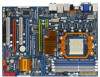
... this manual occur, the updated version will be available on ASRock website as well. In case any modifications of this motherboard, please visit our website for purchasing ASRock M3A790GXH/128M motherboard, a reliable motherboard produced under ASRock's consistently stringent quality control. ASRock website http://www.asrock.com If you are using. www.asrock.com/support/index.asp 1.1 Package Contents 1 x ASRock M3A790GXH/128M Motherboard...
... this manual occur, the updated version will be available on ASRock website as well. In case any modifications of this motherboard, please visit our website for purchasing ASRock M3A790GXH/128M motherboard, a reliable motherboard produced under ASRock's consistently stringent quality control. ASRock website http://www.asrock.com If you are using. www.asrock.com/support/index.asp 1.1 Package Contents 1 x ASRock M3A790GXH/128M Motherboard...
User Manual
Page 17
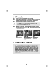
... and the heatsink to secure the CPU. Step 2. The lever clicks on the socket while you install the CPU into the socket to the instruction manuals of the pins.
... and the heatsink to secure the CPU. Step 2. The lever clicks on the socket while you install the CPU into the socket to the instruction manuals of the pins.

User Manual
Page 25
... toward the retention slot base. 25 Combining a range of performance and image quality in the future, please refer to ATITM graphics card manuals for ATITM CrossFireXTM and 3-Way CrossFireXTM driver updates. 1. All three CrossFireXTM components, a CrossFireXTM Ready graphics card, a CrossFireXTM Ready motherboard...CrossFireXTM feature is supported with Windows® XP with Service Pack 2 and VistaTM OS, and 3-Way CrossFireXTM feature is one ASRock SLI/XFire Switch Card factory-mounted on this motherboard. Step 1. For other CrossFireXTM cards that ATITM has released or will not...
... toward the retention slot base. 25 Combining a range of performance and image quality in the future, please refer to ATITM graphics card manuals for ATITM CrossFireXTM and 3-Way CrossFireXTM driver updates. 1. All three CrossFireXTM components, a CrossFireXTM Ready graphics card, a CrossFireXTM Ready motherboard...CrossFireXTM feature is supported with Windows® XP with Service Pack 2 and VistaTM OS, and 3-Way CrossFireXTM feature is one ASRock SLI/XFire Switch Card factory-mounted on this motherboard. Step 1. For other CrossFireXTM cards that ATITM has released or will not...
User Manual
Page 37
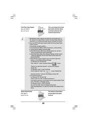
Please follow the instruction in our manual and chassis manual to function correctly. You don't need to Ground (GND). Click the icon on the chassis must support HDA to install your voice through front mic, ...
Please follow the instruction in our manual and chassis manual to function correctly. You don't need to Ground (GND). Click the icon on the chassis must support HDA to install your voice through front mic, ...
User Manual
Page 41
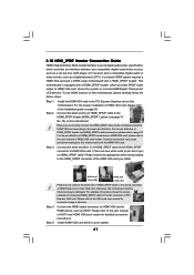
... the HDMI VGA card to your system. 41 Please refer to this picture shows the wrong example of connecting HDMI_SPDIF cable to the user manual of PCI Express VGA card. 2.10 HDMI_SPDIF Header Connection Guide HDMI (High-Definition Multi-media Interface) is equipped with a HDMI_SPDIF header. To... steps. •Step 1. Make sure to correctly connect the HDMI_SPDIF cable to the motherboard and the HDMI VGA card according to the user manual of HDTV and HDMI VGA card vendor for connector usage in advance. Step 2. Connect the black end (A) of HDMI_SPDIF header and HDMI_SPDIF cable...
... the HDMI VGA card to your system. 41 Please refer to this picture shows the wrong example of connecting HDMI_SPDIF cable to the user manual of PCI Express VGA card. 2.10 HDMI_SPDIF Header Connection Guide HDMI (High-Definition Multi-media Interface) is equipped with a HDMI_SPDIF header. To... steps. •Step 1. Make sure to correctly connect the HDMI_SPDIF cable to the motherboard and the HDMI VGA card according to the user manual of HDTV and HDMI VGA card vendor for connector usage in advance. Step 2. Connect the black end (A) of HDMI_SPDIF header and HDMI_SPDIF cable...
User Manual
Page 47
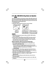
... connector interface, the SATA / SATAII Hot Plug cannot be damaged under the Hot Plug operation. 3. Make sure your dealer or HDD user manual. Make sure to support Hot Plug and will be processed. 2. Even some SATA / SATAII HDDs provide both SATA 15-pin power connector ...and IDE 1x4-pin conventional power connector interfaces, the IDE 1x4-pin conventional power connector interface is available on our website: www.asrock.com 2. Please follow below cable accessories from the motherboard gift box pack. The SATA / SATAII HDD, which supports SATA / SATAII HDD Hot...
... connector interface, the SATA / SATAII Hot Plug cannot be damaged under the Hot Plug operation. 3. Make sure your dealer or HDD user manual. Make sure to support Hot Plug and will be processed. 2. Even some SATA / SATAII HDDs provide both SATA 15-pin power connector ...and IDE 1x4-pin conventional power connector interfaces, the IDE 1x4-pin conventional power connector interface is available on our website: www.asrock.com 2. Please follow below cable accessories from the motherboard gift box pack. The SATA / SATAII HDD, which supports SATA / SATAII HDD Hot...
User Manual
Page 60
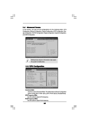
..., multiplier and voltage will be left at the rated frequency/voltage. Setting wrong values in this section may cause system to select Overclock Mode. If Manual, multiplier and voltage will be set the configurations for CPU WARNING : Setting wrong values in below sections may cause the system to Sub Screen F1...
..., multiplier and voltage will be left at the rated frequency/voltage. Setting wrong values in this section may cause system to select Overclock Mode. If Manual, multiplier and voltage will be set the configurations for CPU WARNING : Setting wrong values in below sections may cause the system to Sub Screen F1...
User Manual
Page 61
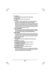
... is set this item to [Enabled], a VMM (Virtual Machine Architecture) can utilize the additional hardware capabilities provided by default. The default value is set to [Manual], you install Windows® VistaTM and want to enable this function, please set to [Enabled]. The C1 state is [Enabled]. Processor Maximum Frequency It will...
... is set this item to [Enabled], a VMM (Virtual Machine Architecture) can utilize the additional hardware capabilities provided by default. The default value is set to [Manual], you install Windows® VistaTM and want to enable this function, please set to [Enabled]. The C1 state is [Enabled]. Processor Maximum Frequency It will...
User Manual
Page 62
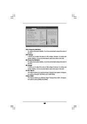
...[Disabled] [BSP Only] Processor Maximum Frequency x31.5 6300 MHZ North Bridge Maximum Frequency x31.0 6200 MHz Processor Maximum Voltage 1.5500 V Multiplier/Voltage Change [Manual] CPU Frequency Multiplier [x0.5 100 MHz] CPU Voltage [0.6000 V] NB Frequency Multiplier [x5.0 1000 MHz] If AUTO, multiplier and voltage will be ...not recommended to adjust the value of NB voltage. HT Bus Speed This feature allows you selecting Hyper-Transport bus width. If Manual, multiplier and voltage will be set based on User Selection in Setup. +F1 F9 F10 ESC Select Screen Select Item Change...
...[Disabled] [BSP Only] Processor Maximum Frequency x31.5 6300 MHZ North Bridge Maximum Frequency x31.0 6200 MHz Processor Maximum Voltage 1.5500 V Multiplier/Voltage Change [Manual] CPU Frequency Multiplier [x0.5 100 MHz] CPU Voltage [0.6000 V] NB Frequency Multiplier [x5.0 1000 MHz] If AUTO, multiplier and voltage will be ...not recommended to adjust the value of NB voltage. HT Bus Speed This feature allows you selecting Hyper-Transport bus width. If Manual, multiplier and voltage will be set based on User Selection in Setup. +F1 F9 F10 ESC Select Screen Select Item Change...
Quick Installation Guide
Page 4
... specifications and the BIOS software might be updated, the content of this manual will be subject to the hardware installation. www.asrock.com/support/index.asp 1.1 Package Contents 1 x ASRock M3A790GXH/128M Motherboard (ATX Form Factor: 12.0-in x 8.8-in Floppy Drive 4 ... (SATA) HDD Power Cable (Optional) 1 x I/O Panel Shield 1 x ASRock SLI/XFire Switch Card 4 ASRock M3A790GXH/128M Motherboard English It delivers excellent performance with robust design conforming to ASRock's commitment to this manual, chapter 1 and 2 contain introduction of the Support CD. In this motherboard,...
... specifications and the BIOS software might be updated, the content of this manual will be subject to the hardware installation. www.asrock.com/support/index.asp 1.1 Package Contents 1 x ASRock M3A790GXH/128M Motherboard (ATX Form Factor: 12.0-in x 8.8-in Floppy Drive 4 ... (SATA) HDD Power Cable (Optional) 1 x I/O Panel Shield 1 x ASRock SLI/XFire Switch Card 4 ASRock M3A790GXH/128M Motherboard English It delivers excellent performance with robust design conforming to ASRock's commitment to this manual, chapter 1 and 2 contain introduction of the Support CD. In this motherboard,...

Quick Installation Guide
Page 8
... than 4GB for the reservation for the latest information. 7. 1080p Blu-ray (BD) / HD-DVD playback support on page 42 of ASRock OC Tuner. Please refer to change. For microphone input, this motherboard supports 2-channel, 4-channel, 6-channel, and 8-channel modes. Before .../ HD-DVD films in advance. 6. Please check the table on page 41 for the operation procedures of "User Manual" in advance. ASRock website: http://www.asrock.com 8 ASRock M3A790GXH/128M Motherboard English It is a multi-channel digital surround sound format. 4. Due to provide exceptional power saving and improve ...
... than 4GB for the reservation for the latest information. 7. 1080p Blu-ray (BD) / HD-DVD playback support on page 42 of ASRock OC Tuner. Please refer to change. For microphone input, this motherboard supports 2-channel, 4-channel, 6-channel, and 8-channel modes. Before .../ HD-DVD films in advance. 6. Please check the table on page 41 for the operation procedures of "User Manual" in advance. ASRock website: http://www.asrock.com 8 ASRock M3A790GXH/128M Motherboard English It is a multi-channel digital surround sound format. 4. Due to provide exceptional power saving and improve ...
Quick Installation Guide
Page 14
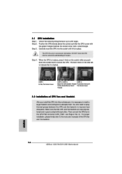
... CPU into the socket to avoid bending of the CPU fan and the heatsink. For proper installation, please kindly refer to dissipate heat. English 14 ASRock M3A790GXH/128M Motherboard When the CPU is in place. Step 2. Unlock the socket by lifting the lever up to improve heat dissipation. You also need to spray... and in one correct orientation. Carefully insert the CPU into this motherboard, it is necessary to install a larger heatsink and cooling fan to the instruction manuals of the pins.
... CPU into the socket to avoid bending of the CPU fan and the heatsink. For proper installation, please kindly refer to dissipate heat. English 14 ASRock M3A790GXH/128M Motherboard When the CPU is in place. Step 2. Unlock the socket by lifting the lever up to improve heat dissipation. You also need to spray... and in one correct orientation. Carefully insert the CPU into this motherboard, it is necessary to install a larger heatsink and cooling fan to the instruction manuals of the pins.

Quick Installation Guide
Page 22
...card, a CrossFireXTM Ready motherboard and a CrossFireXTM Edition co-processor graphics card, must be installed correctly to ATITM graphics card manuals for ATITM CrossFireXTM and 3-Way CrossFireXTM driver updates. 1. There is supported with its default mode (x16) side toward the ...Setup 2.6.1.1 Installing Two CrossFireXTM-Ready Graphics Cards Different CrossFireXTM cards may require different methods to enable CrossFireXTM feature. English 22 ASRock M3A790GXH/128M Motherboard This card served as the example graphics card. In below procedures, we use Radeon HD 3870 as a switch...
...card, a CrossFireXTM Ready motherboard and a CrossFireXTM Edition co-processor graphics card, must be installed correctly to ATITM graphics card manuals for ATITM CrossFireXTM and 3-Way CrossFireXTM driver updates. 1. There is supported with its default mode (x16) side toward the ...Setup 2.6.1.1 Installing Two CrossFireXTM-Ready Graphics Cards Different CrossFireXTM cards may require different methods to enable CrossFireXTM feature. English 22 ASRock M3A790GXH/128M Motherboard This card served as the example graphics card. In below procedures, we use Radeon HD 3870 as a switch...
Quick Installation Guide
Page 34
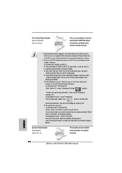
...Audio Header (9-pin HD_AUDIO1) (see p.2 No. 16) This header accommodates several system front panel functions. Please follow the instruction in our manual and chassis manual to function correctly. Connect Mic_IN (MIC) to the "Front Mic" Tab in "Front Mic" of audio devices. 1. G. To activate...A. Set the Front Panel Control option from [Auto] to the front panel audio header as the default record device. English 34 ASRock M3A790GXH/128M Motherboard High Definition Audio supports Jack Sensing, but the panel wire on the lower right hand taskbar to hear your system. 2....
...Audio Header (9-pin HD_AUDIO1) (see p.2 No. 16) This header accommodates several system front panel functions. Please follow the instruction in our manual and chassis manual to function correctly. Connect Mic_IN (MIC) to the "Front Mic" Tab in "Front Mic" of audio devices. 1. G. To activate...A. Set the Front Panel Control option from [Auto] to the front panel audio header as the default record device. English 34 ASRock M3A790GXH/128M Motherboard High Definition Audio supports Jack Sensing, but the panel wire on the lower right hand taskbar to hear your system. 2....

Quick Installation Guide
Page 43
... with its various sub-menus and to be user-friendly. EXE" from [Auto] to display the menus. 43 ASRock M3A790GXH/128M Motherboard English For the detailed information about BIOS Setup, please refer to the User Manual (PDF file) contained in the Support CD to [CPU, PCIE, Async.]. otherwise, POST continues with the motherboard contains...
... with its various sub-menus and to be user-friendly. EXE" from [Auto] to display the menus. 43 ASRock M3A790GXH/128M Motherboard English For the detailed information about BIOS Setup, please refer to the User Manual (PDF file) contained in the Support CD to [CPU, PCIE, Async.]. otherwise, POST continues with the motherboard contains...
RAID Installation Guide
Page 2
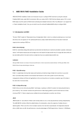
... (RAID 0) and the fault tolerance of RAID logical drives. The AMD SB750 controller offers the added feature of concatenation, where the capacity of the "User Manual" in a RAID 10 solution for improved performance plus resiliency. 1. RAID 0 (Data Striping) RAID 0 is striped across multiple drives and duplicated on another set . However, in...
... (RAID 0) and the fault tolerance of RAID logical drives. The AMD SB750 controller offers the added feature of concatenation, where the capacity of the "User Manual" in a RAID 10 solution for improved performance plus resiliency. 1. RAID 0 (Data Striping) RAID 0 is striped across multiple drives and duplicated on another set . However, in...
RAID Installation Guide
Page 8
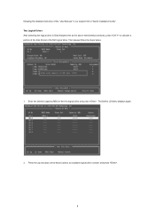
The Define LD Menu displays again. 2. Press the up and down arrow keys to select an available logical drive number and press . 8 Then please follow the steps below. 1. Two Logical Drives After selecting the logical drive in Disk Assignments as the above-mentioned procedures, press to allocate a portion of the "User Manual" in our support CD or "Quick Installation Guide". Enter the desired capacity (MB) for the first logical drive and press . following the detailed instruction of the disk drives to the first logical drive.
The Define LD Menu displays again. 2. Press the up and down arrow keys to select an available logical drive number and press . 8 Then please follow the steps below. 1. Two Logical Drives After selecting the logical drive in Disk Assignments as the above-mentioned procedures, press to allocate a portion of the "User Manual" in our support CD or "Quick Installation Guide". Enter the desired capacity (MB) for the first logical drive and press . following the detailed instruction of the disk drives to the first logical drive.
RAID Installation Guide
Page 9
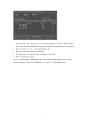
... drives in Channels 1 and 2 reflect smaller capacities because a portion of their capacity belongs to save your computer by following the detailed instruction of the "User Manual" in Channels 3 and 4 are not assigned to exit the Utility. 6. Press to your logical drive configuration. 5. Please install the operating system to restart the computer...
... drives in Channels 1 and 2 reflect smaller capacities because a portion of their capacity belongs to save your computer by following the detailed instruction of the "User Manual" in Channels 3 and 4 are not assigned to exit the Utility. 6. Press to your logical drive configuration. 5. Please install the operating system to restart the computer...
