
User Manual
Page 4
...Package Contents 1 1.2 Specifications 2 1.3 Motherboard Layout 7 1.4 I/O Panel 9 Chapter 2 Installation 13 2.1 Installing the CPU 14 2.2 Installing the CPU Fan and Heatsink 17 2.3 Installation of Memory Modules (DIMM) 18 2.4 Expansion Slots (PCI Express Slots) 20 2.5 Jumpers Setup 22 2.6 Onboard Headers and Connectors 23 2.7 Smart Switches 29 2.8 Dr. Debug 30 2.9 SLITM , 3-Way SLITMand Quad SLITM Operation Guide 32 2.9.1 Installing Two SLITM-Ready Graphics Cards 32 2.9.2 Installing Three SLITM-Ready Graphics Cards 34 2.9.3 Driver Installation and Setup 36 2.10...
...Package Contents 1 1.2 Specifications 2 1.3 Motherboard Layout 7 1.4 I/O Panel 9 Chapter 2 Installation 13 2.1 Installing the CPU 14 2.2 Installing the CPU Fan and Heatsink 17 2.3 Installation of Memory Modules (DIMM) 18 2.4 Expansion Slots (PCI Express Slots) 20 2.5 Jumpers Setup 22 2.6 Onboard Headers and Connectors 23 2.7 Smart Switches 29 2.8 Dr. Debug 30 2.9 SLITM , 3-Way SLITMand Quad SLITM Operation Guide 32 2.9.1 Installing Two SLITM-Ready Graphics Cards 32 2.9.2 Installing Three SLITM-Ready Graphics Cards 34 2.9.3 Driver Installation and Setup 36 2.10...
User Manual
Page 7
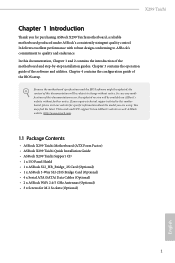
... I/O Panel Shield • 1 x ASRock SLI_HB_Bridge_2S Card (Optional) • 1 x ASRock 3-Way SLI-2S1S Bridge Card (Optional) • 4 x Serial ATA (SATA) Data Cables (Optional) • 2 x ASRock WiFi 2.4/5 GHz Antennas (Optional) • 3 x Screws for purchasing ASRock X299 Taichi motherboard, a reliable motherboard produced under ASRock's consistently stringent quality control. If you for M.2 Sockets (Optional) 1 English You may find the latest VGA cards and CPU support list on ASRock's website without notice. Chapter 4 contains the configuration guide of the BIOS setup. It...
... I/O Panel Shield • 1 x ASRock SLI_HB_Bridge_2S Card (Optional) • 1 x ASRock 3-Way SLI-2S1S Bridge Card (Optional) • 4 x Serial ATA (SATA) Data Cables (Optional) • 2 x ASRock WiFi 2.4/5 GHz Antennas (Optional) • 3 x Screws for purchasing ASRock X299 Taichi motherboard, a reliable motherboard produced under ASRock's consistently stringent quality control. If you for M.2 Sockets (Optional) 1 English You may find the latest VGA cards and CPU support list on ASRock's website without notice. Chapter 4 contains the configuration guide of the BIOS setup. It...

User Manual
Page 10
...on USB3_12 ports. • 4 x USB 3.0 Ports (Supports ESD Protection (ASRock Full Spike Protection)) • 2 x RJ-45 LAN Ports with LED (ACT/LINK LED and SPEED LED) • 1 x BIOS Flashback Switch • 1 x Clear CMOS Switch • HD Audio Jacks: Rear Speaker / Central / Bass / Line in / Front Speaker / Microphone (Gold Audio Jacks) Storage • 8 x SATA3 6.0 Gb/s Connectors, support RAID (RAID 0, RAID 1, RAID 5, RAID 10, Intel Rapid Storage Technology 15 and Intel Smart Response Technology), NCQ, AHCI and Hot Plug* * If M2_1 is occupied by a SATA-type M.2 device, SATA3_1 will...
...on USB3_12 ports. • 4 x USB 3.0 Ports (Supports ESD Protection (ASRock Full Spike Protection)) • 2 x RJ-45 LAN Ports with LED (ACT/LINK LED and SPEED LED) • 1 x BIOS Flashback Switch • 1 x Clear CMOS Switch • HD Audio Jacks: Rear Speaker / Central / Bass / Line in / Front Speaker / Microphone (Gold Audio Jacks) Storage • 8 x SATA3 6.0 Gb/s Connectors, support RAID (RAID 0, RAID 1, RAID 5, RAID 10, Intel Rapid Storage Technology 15 and Intel Smart Response Technology), NCQ, AHCI and Hot Plug* * If M2_1 is occupied by a SATA-type M.2 device, SATA3_1 will...
User Manual
Page 11
... fan power. • 2 x Chassis Fan Connectors (4-pin) (Smart Fan Speed Con- nector) • 1 x 8 pin 12V Power Connector (Hi-Density Power Connec- X299 Taichi • 2 x Ultra M.2 Sockets (M2_1 and M2_3), support M Key type 2230/2242/2260/2280 M.2 SATA3 6.0 Gb/s module and M.2 PCI Express module up to Gen3 x4 (32 Gb/s)** ** Supports Intel® OptaneTM Technology ** Supports NVMe SSD as boot disks ** Supports ASRock U.2 Kit Connector • 1 x Virtual RAID On CPU Header • 1 x TPM Header • 1 x Power LED and Speaker Header • 2 x RGB LED Headers * Support...
... fan power. • 2 x Chassis Fan Connectors (4-pin) (Smart Fan Speed Con- nector) • 1 x 8 pin 12V Power Connector (Hi-Density Power Connec- X299 Taichi • 2 x Ultra M.2 Sockets (M2_1 and M2_3), support M Key type 2230/2242/2260/2280 M.2 SATA3 6.0 Gb/s module and M.2 PCI Express module up to Gen3 x4 (32 Gb/s)** ** Supports Intel® OptaneTM Technology ** Supports NVMe SSD as boot disks ** Supports ASRock U.2 Kit Connector • 1 x Virtual RAID On CPU Header • 1 x TPM Header • 1 x Power LED and Speaker Header • 2 x RGB LED Headers * Support...

User Manual
Page 14
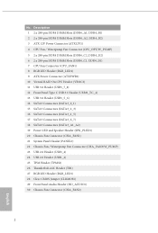
...6 2 x 288-pin DDR4 DIMM Slots (DDR4_C1, DDR4_D1) 7 CPU Fan Connector (CPU_FAN1) 8 RGB LED Header (RGB_LED2) 9 ATX Power Connector (ATXPWR1) 10 Virtual RAID On CPU Header (VROC1) 11 USB 3.0 Header (USB3_7_8) 12 Front Panel Type C USB 3.1 Header (USB31_TC_2) 13 USB 3.0 Header (USB3_5_6) 14 SATA3 Connectors (SATA3_0_1) 15 SATA3 Connectors (SATA3_2_3) 16 SATA3 Connectors (SATA3_4_5) 17 SATA3 Connectors (SATA3_6_7) 18 SATA3 Connectors (SATA3_A1_A2) 19 Power LED and Speaker Header (SPK_PLED1) 20 Chassis Fan Connector (CHA_FAN1) 21 System Panel Header (PANEL1) 22 Chassis Fan / Waterpump Fan Connector...
...6 2 x 288-pin DDR4 DIMM Slots (DDR4_C1, DDR4_D1) 7 CPU Fan Connector (CPU_FAN1) 8 RGB LED Header (RGB_LED2) 9 ATX Power Connector (ATXPWR1) 10 Virtual RAID On CPU Header (VROC1) 11 USB 3.0 Header (USB3_7_8) 12 Front Panel Type C USB 3.1 Header (USB31_TC_2) 13 USB 3.0 Header (USB3_5_6) 14 SATA3 Connectors (SATA3_0_1) 15 SATA3 Connectors (SATA3_2_3) 16 SATA3 Connectors (SATA3_4_5) 17 SATA3 Connectors (SATA3_6_7) 18 SATA3 Connectors (SATA3_A1_A2) 19 Power LED and Speaker Header (SPK_PLED1) 20 Chassis Fan Connector (CHA_FAN1) 21 System Panel Header (PANEL1) 22 Chassis Fan / Waterpump Fan Connector...

User Manual
Page 35
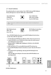
X299 Taichi 2.7 Smart Switches The motherboard has two smart switches: Clear CMOS Switch and BIOS Flashback Switch, allowing users to blink. 6. Copy the BIOS file to your USB flash drive.Please make sure the file system of your USB drive to "creative.rom" and plug your USB flash drive must be FAT32. 3. Then the LED starts to clear the CMOS values or flash the BIOS. This function is not operating properly. 46 1 2 3 57 English 17 16 15 14 USB BIOS Flashback port 13 12 10 98...
X299 Taichi 2.7 Smart Switches The motherboard has two smart switches: Clear CMOS Switch and BIOS Flashback Switch, allowing users to blink. 6. Copy the BIOS file to your USB flash drive.Please make sure the file system of your USB drive to "creative.rom" and plug your USB flash drive must be FAT32. 3. Then the LED starts to clear the CMOS values or flash the BIOS. This function is not operating properly. 46 1 2 3 57 English 17 16 15 14 USB BIOS Flashback port 13 12 10 98...
User Manual
Page 36
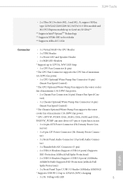
... press reset or clear CMOS. 92 - 99 Problem related to IDE or SATA devices. If the problem still exists, please remove all SATA devices. Please clear CMOS, re-install the memory and VGA card, and remove other USB, PCI devices. 01 - 54 (except 0d), 5A- 60 Problem related to memory. Please re-install PCI-E devices or try using other memory modules. 61 - 91 Chipset initialization error. b0 Problem related to memory. Please re-install the CPU and memory. If the problem still exists, please install only one memory...
... press reset or clear CMOS. 92 - 99 Problem related to IDE or SATA devices. If the problem still exists, please remove all SATA devices. Please clear CMOS, re-install the memory and VGA card, and remove other USB, PCI devices. 01 - 54 (except 0d), 5A- 60 Problem related to memory. Please re-install PCI-E devices or try using other memory modules. 61 - 91 Chipset initialization error. b0 Problem related to memory. Please re-install the CPU and memory. If the problem still exists, please install only one memory...
User Manual
Page 43
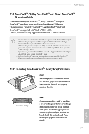
... mode. 5. You should only use a AMD certified PSU. Download the drivers from the AMD's website: www.amd.com 3. English CrossFire Bridge Step 2 Connect two graphics cards by installing a CrossFire Bridge on the CrossFire Bridge Interconnects on the slots. It is recommended to your graphics card vendor for details.) 37 Please refer to three identical PCI Express x16 graphics cards. X299 Taichi 2.10 CrossFireXTM, 3-Way CrossFireXTM and Quad CrossFireXTM Operation Guide This motherboard supports...
... mode. 5. You should only use a AMD certified PSU. Download the drivers from the AMD's website: www.amd.com 3. English CrossFire Bridge Step 2 Connect two graphics cards by installing a CrossFire Bridge on the CrossFire Bridge Interconnects on the slots. It is recommended to your graphics card vendor for details.) 37 Please refer to three identical PCI Express x16 graphics cards. X299 Taichi 2.10 CrossFireXTM, 3-Way CrossFireXTM and Quad CrossFireXTM Operation Guide This motherboard supports...

User Manual
Page 46
... and boot into OS. English 40 2.10.3 Driver Installation and Setup Step 1 Power on your computer. We recommend using this utility to uninstall any VGA drivers installed in the Windows® system tray. AMD Catalyst Control Center Step 4 Double-click the AMD Catalyst Control Center icon in your graphics card and click Apply. Step 2 Remove the AMD drivers if you have any previously installed Catalyst drivers prior to your system. Then select Enable AMD...
... and boot into OS. English 40 2.10.3 Driver Installation and Setup Step 1 Power on your computer. We recommend using this utility to uninstall any VGA drivers installed in the Windows® system tray. AMD Catalyst Control Center Step 4 Double-click the AMD Catalyst Control Center icon in your graphics card and click Apply. Step 2 Remove the AMD drivers if you have any previously installed Catalyst drivers prior to your system. Then select Enable AMD...
User Manual
Page 51
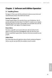
... motherboard supports. Drivers Menu The drivers compatible to your system will be auto-detected and listed on a specific item then follow the order from top to bottom to install those required drivers. Running The Support CD To begin using the support CD, insert the CD into your computer. If the Main Menu does not appear automatically, locate and double click on the file "ASRSETUP.EXE" in your CD-ROM drive...
... motherboard supports. Drivers Menu The drivers compatible to your system will be auto-detected and listed on a specific item then follow the order from top to bottom to install those required drivers. Running The Support CD To begin using the support CD, insert the CD into your computer. If the Main Menu does not appear automatically, locate and double click on the file "ASRSETUP.EXE" in your CD-ROM drive...

User Manual
Page 88
... connectivity. Deep Sleep Configure deep sleep mode for all PCH DMI devices. PCH PCIE ASPM Support This option enables/disables the ASPM support for power saving when the computer is installed. AQUANTIA 10G LAN Enable or disable the onboard network interface controller (AQUANTIA 10G LAN). Set to Auto to enable onboard HD audio and automatically disable it when a sound card is shut down. 82 English PCI Express Native Control Select Enable for PCIE5. Onboard LAN Enable or disable the onboard network interface controller. PCH DMI ASPM Support This option enables/disables the ASPM support...
... connectivity. Deep Sleep Configure deep sleep mode for all PCH DMI devices. PCH PCIE ASPM Support This option enables/disables the ASPM support for power saving when the computer is installed. AQUANTIA 10G LAN Enable or disable the onboard network interface controller (AQUANTIA 10G LAN). Set to Auto to enable onboard HD audio and automatically disable it when a sound card is shut down. 82 English PCI Express Native Control Select Enable for PCIE5. Onboard LAN Enable or disable the onboard network interface controller. PCH DMI ASPM Support This option enables/disables the ASPM support...

User Manual
Page 96
...), Auto ASRock Internet Flash downloads and updates the latest UEFI firmware version from the support CD to RAID, then you can start installing the operating system in your UEFI. After copying the drivers please change the SATA mode to your PC. Please setup network configuration before using Internet Flash. *For BIOS backup and recovery purpose, it is recommended to update your USB pen drive before using this function. 90 English Instant Flash Save UEFI files in your USB storage device and run Instant Flash to plug...
...), Auto ASRock Internet Flash downloads and updates the latest UEFI firmware version from the support CD to RAID, then you can start installing the operating system in your UEFI. After copying the drivers please change the SATA mode to your PC. Please setup network configuration before using Internet Flash. *For BIOS backup and recovery purpose, it is recommended to update your USB pen drive before using this function. 90 English Instant Flash Save UEFI files in your USB storage device and run Instant Flash to plug...
User Manual
Page 97
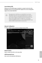
Network Configuration Use this to download the UEFI firmware. 91 English For safety issues, users are outdated or corrupted, switch to the other flash ROM and execute Secure Backup UEFI to duplicate the current working copy of the BIOS files to the active BIOS to ensure normal system operation. Internet Setting Enable or disable sound effects in the setup utility. This motherboard has two BIOS chips, an active BIOS (BIOS_A) and a backup BIOS (BIOS_B), which BIOS is corrupted...
Network Configuration Use this to download the UEFI firmware. 91 English For safety issues, users are outdated or corrupted, switch to the other flash ROM and execute Secure Backup UEFI to duplicate the current working copy of the BIOS files to the active BIOS to ensure normal system operation. Internet Setting Enable or disable sound effects in the setup utility. This motherboard has two BIOS chips, an active BIOS (BIOS_A) and a backup BIOS (BIOS_B), which BIOS is corrupted...

User Manual
Page 101
... Technology Enable/disable Intel PTT in the UEFI Setup Utility. Supervisor Password Set or change the password for the user account. User Password Set or change the password for the administrator account. Disable this section you may also clear the user password. Only the administrator has authority to change the settings in the UEFI Setup Utility. You may set or change the supervisor/user password for the system. X299 Taichi 4.9 Security Screen In this option to enable or disable support for Windows 8.1 Secure Boot. Users are unable to change the settings...
... Technology Enable/disable Intel PTT in the UEFI Setup Utility. Supervisor Password Set or change the password for the user account. User Password Set or change the password for the administrator account. Disable this section you may also clear the user password. Only the administrator has authority to change the settings in the UEFI Setup Utility. You may set or change the supervisor/user password for the system. X299 Taichi 4.9 Security Screen In this option to enable or disable support for Windows 8.1 Secure Boot. Users are unable to change the settings...
Quick Installation Guide
Page 4
...6 2 x 288-pin DDR4 DIMM Slots (DDR4_C1, DDR4_D1) 7 CPU Fan Connector (CPU_FAN1) 8 RGB LED Header (RGB_LED2) 9 ATX Power Connector (ATXPWR1) 10 Virtual RAID On CPU Header (VROC1) 11 USB 3.0 Header (USB3_7_8) 12 Front Panel Type C USB 3.1 Header (USB31_TC_2) 13 USB 3.0 Header (USB3_5_6) 14 SATA3 Connectors (SATA3_0_1) 15 SATA3 Connectors (SATA3_2_3) 16 SATA3 Connectors (SATA3_4_5) 17 SATA3 Connectors (SATA3_6_7) 18 SATA3 Connectors (SATA3_A1_A2) 19 Power LED and Speaker Header (SPK_PLED1) 20 Chassis Fan Connector (CHA_FAN1) 21 System Panel Header (PANEL1) 22 Chassis Fan / Waterpump Fan Connector...
...6 2 x 288-pin DDR4 DIMM Slots (DDR4_C1, DDR4_D1) 7 CPU Fan Connector (CPU_FAN1) 8 RGB LED Header (RGB_LED2) 9 ATX Power Connector (ATXPWR1) 10 Virtual RAID On CPU Header (VROC1) 11 USB 3.0 Header (USB3_7_8) 12 Front Panel Type C USB 3.1 Header (USB31_TC_2) 13 USB 3.0 Header (USB3_5_6) 14 SATA3 Connectors (SATA3_0_1) 15 SATA3 Connectors (SATA3_2_3) 16 SATA3 Connectors (SATA3_4_5) 17 SATA3 Connectors (SATA3_6_7) 18 SATA3 Connectors (SATA3_A1_A2) 19 Power LED and Speaker Header (SPK_PLED1) 20 Chassis Fan Connector (CHA_FAN1) 21 System Panel Header (PANEL1) 22 Chassis Fan / Waterpump Fan Connector...
Quick Installation Guide
Page 31
.... 5. Download the latest BIOS file from ASRock's website : http://www.asrock.com. 2. This function is not installed; Please follow the steps below. 1. Wait until the LED stops blinking, indicating that BIOS flashing has been completed. *If the LED light turns solid green, this means that the CPU is workable only when you power off your computer and unplug the power supply. X299 Taichi 2.7 Smart Switches The motherboard has two smart switches: Clear CMOS Switch and BIOS Flashback Switch...
.... 5. Download the latest BIOS file from ASRock's website : http://www.asrock.com. 2. This function is not installed; Please follow the steps below. 1. Wait until the LED stops blinking, indicating that BIOS flashing has been completed. *If the LED light turns solid green, this means that the CPU is workable only when you power off your computer and unplug the power supply. X299 Taichi 2.7 Smart Switches The motherboard has two smart switches: Clear CMOS Switch and BIOS Flashback Switch...

Quick Installation Guide
Page 32
..., please install only one memory module or try using other devices. If the problem still exists, please clear CMOS and try removing all PCI-E devices or try using other memory modules. 2.8 Dr. Debug Dr. Debug is installed correctly and then clear CMOS. 0d Problem related to memory. Code Description 00 Please check if the CPU is used to IDE or SATA devices. Please press reset or clear CMOS. 92 - 99 Problem related to memory. b0 Problem related to PCI-E devices. English...
..., please install only one memory module or try using other devices. If the problem still exists, please clear CMOS and try removing all PCI-E devices or try using other memory modules. 2.8 Dr. Debug Dr. Debug is installed correctly and then clear CMOS. 0d Problem related to memory. Code Description 00 Please check if the CPU is used to IDE or SATA devices. Please press reset or clear CMOS. 92 - 99 Problem related to memory. b0 Problem related to PCI-E devices. English...

RAID Installation Guide
Page 7
...configuration changes and exit setup. STEP 1: Setting the BIOS RAID Items After installing the hard disk drives, please set SATA Mode Selection to your USB storage device with RAID functions, please follow the procedures below. Boot your system, and press key to install Windows® 10 64-bit OS on your USB flash drive into a USB port B. Enter UEFI SETUP UTILITY Tool and highlight "Easy RAID Installer". STEP 4: Install Windows® 10 64-bit OS on your RAID configuration. 2.3 Installing Windows® 10 64-bit With RAID Functions If you want to enter BIOS setup...
...configuration changes and exit setup. STEP 1: Setting the BIOS RAID Items After installing the hard disk drives, please set SATA Mode Selection to your USB storage device with RAID functions, please follow the procedures below. Boot your system, and press key to install Windows® 10 64-bit OS on your USB flash drive into a USB port B. Enter UEFI SETUP UTILITY Tool and highlight "Easy RAID Installer". STEP 4: Install Windows® 10 64-bit OS on your RAID configuration. 2.3 Installing Windows® 10 64-bit With RAID Functions If you want to enter BIOS setup...
RAID Installation Guide
Page 23
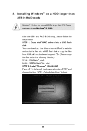
...; RAID drivers into a USB flash disk You can download the drivers from ASRock's website and unzip the files into a USB flash disk or copy the files from ASRock's motherboard support CD. (Please copy the files under the following directory: 32 bit: ..\i386\Win7_Intel.. 64-bit: ..\AMD64\Win7-64_Intel.. After the UEFI and RAID BIOS setup, please follow the steps below. Please make sure to boot. 23 STEP 2: Install Windows® 10 64-bit OS Press to launch boot menu...
...; RAID drivers into a USB flash disk You can download the drivers from ASRock's website and unzip the files into a USB flash disk or copy the files from ASRock's motherboard support CD. (Please copy the files under the following directory: 32 bit: ..\i386\Win7_Intel.. 64-bit: ..\AMD64\Win7-64_Intel.. After the UEFI and RAID BIOS setup, please follow the steps below. Please make sure to boot. 23 STEP 2: Install Windows® 10 64-bit OS Press to launch boot menu...

RAID Installation Guide
Page 25
... will install this hotfix then reboot by itself. Please request the hotfix KB2505454 through this link: http://support.microsoft.com/kb/2505454/ B. E. After installing Windows® 10 64-bit, install the hotfix kb2505454. (This may take about 5 minutes to fix this problem. Please start to boot into Windows® or install driver/utilities. Reboot your system. (It may take more time to install motherboard drivers and utilities...
... will install this hotfix then reboot by itself. Please request the hotfix KB2505454 through this link: http://support.microsoft.com/kb/2505454/ B. E. After installing Windows® 10 64-bit, install the hotfix kb2505454. (This may take about 5 minutes to fix this problem. Please start to boot into Windows® or install driver/utilities. Reboot your system. (It may take more time to install motherboard drivers and utilities...


