
Veriton 3500G/5500G/7500G Service Guide
Page 7
... Power Management Setup 47 PnP/PCI Configurations 50 PC Health Status 52 Frequency Control 54 System Security 55 Supervisor Password 55 User Password 57 Bypassing the Password 58 Load Default Settings 59 Exiting Setup 60 Advanced Options 61 Product Information 61 Advanced BIOS Features 62 Advanced Chipset Features 63 Integrated Peripherals 64 Power Management Setup 65 Frequency Control 67 Chapter 3 Machine Disassembly and Replacement 69 General Information 70 Before You Begin 70 Veriton...
... Power Management Setup 47 PnP/PCI Configurations 50 PC Health Status 52 Frequency Control 54 System Security 55 Supervisor Password 55 User Password 57 Bypassing the Password 58 Load Default Settings 59 Exiting Setup 60 Advanced Options 61 Product Information 61 Advanced BIOS Features 62 Advanced Chipset Features 63 Integrated Peripherals 64 Power Management Setup 65 Frequency Control 67 Chapter 3 Machine Disassembly and Replacement 69 General Information 70 Before You Begin 70 Veriton...

Veriton 3500G/5500G/7500G Service Guide
Page 8
... Disassembling the Veriton 7500/ 7500G 98 Opening the Housing 98 Removing the Front Panel 98 Removing the Modem Card 99 Removing the AGP VGA Card 99 Removing the USB/ Audio Board 100 Removing the DVD-ROM and CD-RW Drive 101 Removing the Floppy Disk Drive 102 Removing the Hard Disk Drive 103 Removing the Intrusion Alarm Cable Module 103 Removing a DIMM 104 Removing the CPU Fan Sink 104 Removing and Installing the Processor 105 Removing and Installing the RTC Battery 105 Removing the Power Supply 106 Removing the LED Activity Indicators With Power Switch Cable...
... Disassembling the Veriton 7500/ 7500G 98 Opening the Housing 98 Removing the Front Panel 98 Removing the Modem Card 99 Removing the AGP VGA Card 99 Removing the USB/ Audio Board 100 Removing the DVD-ROM and CD-RW Drive 101 Removing the Floppy Disk Drive 102 Removing the Hard Disk Drive 103 Removing the Intrusion Alarm Cable Module 103 Removing a DIMM 104 Removing the CPU Fan Sink 104 Removing and Installing the Processor 105 Removing and Installing the RTC Battery 105 Removing the Power Supply 106 Removing the LED Activity Indicators With Power Switch Cable...

Veriton 3500G/5500G/7500G Service Guide
Page 12
... (front and rear). Hardware monitor function ! Cathode-ray tube (CRT) support ! An additional AGP card 1.5V slot, supports 1X, 2X and 4X ! 3-D quality audio system via onboard audio controller ! Connectivity ! One multi-mode parallel port ! CPU SMM (System Management Mode), STOP clock control ! However, you can not use both of them at the back. USB and PS/2 compatible mouse and keyboard interfaces ! PIO mode 4 ! Plug-and-Play (PnP) feature ! ACPI 1.0 b Compliant Power management and Configuration Support ! System...
... (front and rear). Hardware monitor function ! Cathode-ray tube (CRT) support ! An additional AGP card 1.5V slot, supports 1X, 2X and 4X ! 3-D quality audio system via onboard audio controller ! Connectivity ! One multi-mode parallel port ! CPU SMM (System Management Mode), STOP clock control ! However, you can not use both of them at the back. USB and PS/2 compatible mouse and keyboard interfaces ! PIO mode 4 ! Plug-and-Play (PnP) feature ! ACPI 1.0 b Compliant Power management and Configuration Support ! System...

Veriton 3500G/5500G/7500G Service Guide
Page 37
... access time Data Buffer Capacity Interface Pioneer DVD-117RD With CD Diskette Sustained: Max 3.6 MB/s 120ms 512 KBytes IDE/ATAPI Specification With DVD Diskette Sustained: Max8.31MB/s 180ms Chapter 1 27 ATA data transfer modes supported DC Power Requirements (max) Startup (peak) Maximum seeking (RMS) Voltage tolerance MTBF (Mean Time Between Failure) S.M.A.R.T. Floppy disk drive Interface Item MTBF (Mean Time Between Failure) Floppy disk drive controller...
... access time Data Buffer Capacity Interface Pioneer DVD-117RD With CD Diskette Sustained: Max 3.6 MB/s 120ms 512 KBytes IDE/ATAPI Specification With DVD Diskette Sustained: Max8.31MB/s 180ms Chapter 1 27 ATA data transfer modes supported DC Power Requirements (max) Startup (peak) Maximum seeking (RMS) Voltage tolerance MTBF (Mean Time Between Failure) S.M.A.R.T. Floppy disk drive Interface Item MTBF (Mean Time Between Failure) Floppy disk drive controller...

Veriton 3500G/5500G/7500G Service Guide
Page 55
... controller card. Enabled Disabled Enabled Disabled Enabled Disabled Auto Disabled Enabled Disabled Onboard/ AGP PCI Slot Enabled Disabled Button Only Any Key Keyboard 98 Enabled Disabled 3F8/ IRQ4 Auto 2F8/ IRQ3 3E8/ IRQ4 2E8/ IRQ3 Disabled Chapter 2 45 Enabling the on-die AC97 Audio if no add-on PCI Audio device. The options to Auto activates the HDD speed auto-detect function. The mouse driver simulates legacy mouse command and lets you use a USB keyboard during POST or after boot if you enable or disable the USB mouse driver within the onboard BIOS...
... controller card. Enabled Disabled Enabled Disabled Enabled Disabled Auto Disabled Enabled Disabled Onboard/ AGP PCI Slot Enabled Disabled Button Only Any Key Keyboard 98 Enabled Disabled 3F8/ IRQ4 Auto 2F8/ IRQ3 3E8/ IRQ4 2E8/ IRQ3 Disabled Chapter 2 45 Enabling the on-die AC97 Audio if no add-on PCI Audio device. The options to Auto activates the HDD speed auto-detect function. The mouse driver simulates legacy mouse command and lets you use a USB keyboard during POST or after boot if you enable or disable the USB mouse driver within the onboard BIOS...

Veriton 3500G/5500G/7500G Service Guide
Page 58
... Enabled in ACPI and APM Mode) Wake-Up by PCI Card (Function Enabled in ACPI and APM Mode) USB KB Wake-up the system from power failure. If it to User Define to RAM) mode. Set it is selected, the soft power switch on after which the system will go into Suspend mode. This item lets you specify the IDE HDD idle time before the device enters the power down state. Use this menu...
... Enabled in ACPI and APM Mode) Wake-Up by PCI Card (Function Enabled in ACPI and APM Mode) USB KB Wake-up the system from power failure. If it to User Define to RAM) mode. Set it is selected, the soft power switch on after which the system will go into Suspend mode. This item lets you specify the IDE HDD idle time before the device enters the power down state. Use this menu...

Veriton 3500G/5500G/7500G Service Guide
Page 60
... (PS/2 Mouse) IRQ 14 (IDE1) IRQ15 (IDE2) Description Select Enabled to reset Extended System Configuration Data (ESCD) when you exit Setup if you to individually assign the IRQs and DMAs to Manual allows you have installed a new add-on and the system configuration has caused such a serious conflict that PCI cards are the default and suggested settings. Set this option to the ISA and PCI devices. The default is...
... (PS/2 Mouse) IRQ 14 (IDE1) IRQ15 (IDE2) Description Select Enabled to reset Extended System Configuration Data (ESCD) when you exit Setup if you to individually assign the IRQs and DMAs to Manual allows you have installed a new add-on and the system configuration has caused such a serious conflict that PCI cards are the default and suggested settings. Set this option to the ISA and PCI devices. The default is...

Veriton 3500G/5500G/7500G Service Guide
Page 74
... AGP card. On-Chip Video Window size Aperture size for Memory frequency default setup. The default setting by your DRAM's SPD. Memory Frequency for on-board CPU. Video BIOS Cacheable C segment shadow RAM cacheable. Options to Thermal Enables Pentium 4 thermal function - 16 miuntes after POST.(only for ACPI OS) AGP Aperture Size (MB) Aperture size: the size of the system memory for internal register, FWH, and LPC I/F accesses. . The default setting...
... AGP card. On-Chip Video Window size Aperture size for Memory frequency default setup. The default setting by your DRAM's SPD. Memory Frequency for on-board CPU. Video BIOS Cacheable C segment shadow RAM cacheable. Options to Thermal Enables Pentium 4 thermal function - 16 miuntes after POST.(only for ACPI OS) AGP Aperture Size (MB) Aperture size: the size of the system memory for internal register, FWH, and LPC I/F accesses. . The default setting...

Veriton 3500G/5500G/7500G Service Guide
Page 126
... Setup. POST Error Messages List If you cannot run specific disk diagnostic routines. NOTE: When you have deemed it necessary to either turn off the system and change the jumper, or enter Setup and change . This system check can be done through the diagnostics program. If no objects are pressed during POST. System halted CMOS Battery Failed CMOS Checksum Error- Please wait a moment HARD DISK INSTALL FAILURE Hard disk(s) diagnosis fail Keyboard Error Or No Keyboard Present Keyboard...
... Setup. POST Error Messages List If you cannot run specific disk diagnostic routines. NOTE: When you have deemed it necessary to either turn off the system and change the jumper, or enter Setup and change . This system check can be done through the diagnostics program. If no objects are pressed during POST. System halted CMOS Battery Failed CMOS Checksum Error- Please wait a moment HARD DISK INSTALL FAILURE Hard disk(s) diagnosis fail Keyboard Error Or No Keyboard Present Keyboard...
Veriton 3500G/5500G/7500G Service Guide
Page 127
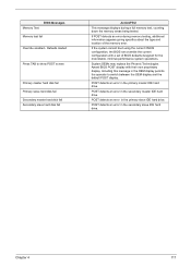
... slave hard disk fail Secondary master hard disk fail Secondary slave hard disk fail Action/FRU This message displays during memory testing, additional information appears giving specifics about the type and location of BIOS defaults designed for the most stable, minimal-performance system operations. BIOS Messages Memory Test: Memory test fail Override enabled - If POST detects an error during a full memory test, counting down the memory areas being tested. If the system cannot boot using the current CMOS configuration, the BIOS...
... slave hard disk fail Secondary master hard disk fail Secondary slave hard disk fail Action/FRU This message displays during memory testing, additional information appears giving specifics about the type and location of BIOS defaults designed for the most stable, minimal-performance system operations. BIOS Messages Memory Test: Memory test fail Override enabled - If POST detects an error during a full memory test, counting down the memory areas being tested. If the system cannot boot using the current CMOS configuration, the BIOS...

Veriton 3500G/5500G/7500G Service Guide
Page 129
... 2. Enter BIOS Setup and Load default settings. 2. Hard disk drive has write error. 1. Hard disk drive LED fails to unload the disk. 2. CD/DVD-ROM may have dirt or foreign material on it . Ensure the CD/DVD-ROM driver is clean before diagnosing any hard disk drive problems. (If only one drive is installed, please make sure the drive is connected to master connector or the drive is pressed and held. 1. CD/DVD-ROM drive can play audio CD but system operates normally. 1. Diskette drive 3. Hard disk drive cable. 3. Speaker power/connection/cable. 4. Diskette drive...
... 2. Enter BIOS Setup and Load default settings. 2. Hard disk drive has write error. 1. Hard disk drive LED fails to unload the disk. 2. CD/DVD-ROM may have dirt or foreign material on it . Ensure the CD/DVD-ROM driver is clean before diagnosing any hard disk drive problems. (If only one drive is installed, please make sure the drive is connected to master connector or the drive is pressed and held. 1. CD/DVD-ROM drive can play audio CD but system operates normally. 1. Diskette drive 3. Hard disk drive cable. 3. Speaker power/connection/cable. 4. Diskette drive...

Veriton 3500G/5500G/7500G Service Guide
Page 130
... sound feature works normally.) Video memory test failed. Display problem: - Speaker power/connection/cable. In Win 98, ensure the telephone application is set to Enabled. 2. Ensure the modem voice-in BIOS Setup or Power Management is configured correctly for your modem and set to Enabled. Load default settings (if screen is installed properly. 1. Video adapter card 4. Modem ring cannot wake up by PCI card is readable). 3. Main board 1. Monitor signal connection/cable. 2. Main board 1. Action/FRU Audio 1. Main board 120 Veriton 3500/5500/7500 Display problem not listed...
... sound feature works normally.) Video memory test failed. Display problem: - Speaker power/connection/cable. In Win 98, ensure the telephone application is set to Enabled. 2. Ensure the modem voice-in BIOS Setup or Power Management is configured correctly for your modem and set to Enabled. Load default settings (if screen is installed properly. 1. Video adapter card 4. Modem ring cannot wake up by PCI card is readable). 3. Main board 1. Monitor signal connection/cable. 2. Main board 1. Action/FRU Audio 1. Main board 120 Veriton 3500/5500/7500 Display problem not listed...

Veriton 3500G/5500G/7500G Service Guide
Page 131
... BIOS Setup of the machine, just above the connector for the printer. Ensure the power override switch (situated at the back of Power Management is not set to the service manual for the power cable) is not running. 1. Power Supply 2. Printing failed. 1. Keyboard Some or all keys on the system. 1. Refer to OFF. 2. Power switch cable assembly. Power switch cable assembly Pressing power switch does not turn off the system.) 1. Error Symptom Action/FRU Parallel/Serial Ports Execute "Load BIOS Default Settings" in BIOS Setup...
... BIOS Setup of the machine, just above the connector for the printer. Ensure the power override switch (situated at the back of Power Management is not set to the service manual for the power cable) is not running. 1. Power Supply 2. Printing failed. 1. Keyboard Some or all keys on the system. 1. Refer to OFF. 2. Power switch cable assembly. Power switch cable assembly Pressing power switch does not turn off the system.) 1. Error Symptom Action/FRU Parallel/Serial Ports Execute "Load BIOS Default Settings" in BIOS Setup...

Veriton 3500G/5500G/7500G Service Guide
Page 174
... main board ID 37 product name 37 system BIOS version 37 system serial number 37 PS/2 keyboard port 11, 14 PS/2 mouse port 10, 14 R Removal and Replacement 69 removing 88, 90, 105 Replacement Assembly, Machine 69 replacing HDD 91 RIMM Removing 80, 103 RMA 127 Routing Map 30 S Security 55 Serial Port 29 Serial port 10, 15 socket memory 24 Socket 370 23 Suspend Mode 34 Switching Power Supply 102W 32 Symptoms List 164 Veriton 3500...
... main board ID 37 product name 37 system BIOS version 37 system serial number 37 PS/2 keyboard port 11, 14 PS/2 mouse port 10, 14 R Removal and Replacement 69 removing 88, 90, 105 Replacement Assembly, Machine 69 replacing HDD 91 RIMM Removing 80, 103 RMA 127 Routing Map 30 S Security 55 Serial Port 29 Serial port 10, 15 socket memory 24 Socket 370 23 Suspend Mode 34 Switching Power Supply 102W 32 Symptoms List 164 Veriton 3500...

Veriton 7500G
Page 8
... Connecting peripherals 29 Connecting your mouse 29 Connecting your keyboard 31 Connecting a monitor 33 Connecting the power cable 34 Turning on your computer 35 Turning off your computer 36 Connecting options 37 Connecting your printer 37 Connecting the modem 38 Connecting to the network 39 Connecting multimedia devices 40 Connecting USB devices 43 4 Upgrading your computer 45 Installation precautions 47 ESD precautions 47 Preinstallation instructions 47 Post-installation instructions 48 Opening your computer 49 To remove the side panel 49 To replace...
... Connecting peripherals 29 Connecting your mouse 29 Connecting your keyboard 31 Connecting a monitor 33 Connecting the power cable 34 Turning on your computer 35 Turning off your computer 36 Connecting options 37 Connecting your printer 37 Connecting the modem 38 Connecting to the network 39 Connecting multimedia devices 40 Connecting USB devices 43 4 Upgrading your computer 45 Installation precautions 47 ESD precautions 47 Preinstallation instructions 47 Post-installation instructions 48 Opening your computer 49 To remove the side panel 49 To replace...

Veriton 7500G
Page 15
... you have checked and done the troubleshooting tips discussed in the "Frequently-asked questions" section on page 77 • If your problem is not listed in your pointing device To clean a regular mouse (with rubber ball) 1 Open the circular cover underneath the mouse. 2 Take out the rubber ball and wipe it with your mouse for maintenance instructions. 5 To clean your area.
... you have checked and done the troubleshooting tips discussed in the "Frequently-asked questions" section on page 77 • If your problem is not listed in your pointing device To clean a regular mouse (with rubber ball) 1 Open the circular cover underneath the mouse. 2 Take out the rubber ball and wipe it with your mouse for maintenance instructions. 5 To clean your area.

Veriton 7500G
Page 19
... and disables the one at the same time. However, you must use both of 1GB . • Power management function • 3.5-inch floppy drive • DVD-ROM, CD-ROM or CD-RW drive • High-capacity, Enhanced-IDE hard disk • Supports USB 2.0 high-performance peripherals Multimedia • 128-bit graphics accelerator installed in the AGP card slot • 3-D quality audio system via onboard audio controller • Audio-in/Line-in, Audio-out...
... and disables the one at the same time. However, you must use both of 1GB . • Power management function • 3.5-inch floppy drive • DVD-ROM, CD-ROM or CD-RW drive • High-capacity, Enhanced-IDE hard disk • Supports USB 2.0 high-performance peripherals Multimedia • 128-bit graphics accelerator installed in the AGP card slot • 3-D quality audio system via onboard audio controller • Audio-in/Line-in, Audio-out...

Veriton 7500G
Page 57
... read the following sections. 47 Installation precautions Before you install any computer component, we recommend that block access to the DIMM sockets or component connector. 5 See the following sections for specific instructions on page 49. 3 Follow the ESD precautions described above before you install a computer component: 1 Do not remove a component from the power outlets. 2 Open your processor, disk drives, expansion boards, and other components.
... read the following sections. 47 Installation precautions Before you install any computer component, we recommend that block access to the DIMM sockets or component connector. 5 See the following sections for specific instructions on page 49. 3 Follow the ESD precautions described above before you install a computer component: 1 Do not remove a component from the power outlets. 2 Open your processor, disk drives, expansion boards, and other components.

Veriton 7500G
Page 66
... CN12 CN13 CN14 CN16 CN17 CN18 CN19 CN20 CN21 CN22 CN23 4 Upgrading your computer Component Battery PS/2 mouse (upper) and keyboard (lower) ports USB ports COM 2 connector Game port Power connector Parallel (upper), serial (left) and monitor (right) ports FDD connector Network (upper) and USB (lower) ports Power connector (12V power) IDE 2 connector IDE 1 connector Line-out (top), line-in (middle), and rear microphonein (bottom) ports Audio FPIO connector CD-in connector Front USB 2.0 connector LAN active LED connector HDD LED connector Power button Intrusion connector Serial IRQ connector
... CN12 CN13 CN14 CN16 CN17 CN18 CN19 CN20 CN21 CN22 CN23 4 Upgrading your computer Component Battery PS/2 mouse (upper) and keyboard (lower) ports USB ports COM 2 connector Game port Power connector Parallel (upper), serial (left) and monitor (right) ports FDD connector Network (upper) and USB (lower) ports Power connector (12V power) IDE 2 connector IDE 1 connector Line-out (top), line-in (middle), and rear microphonein (bottom) ports Audio FPIO connector CD-in connector Front USB 2.0 connector LAN active LED connector HDD LED connector Power button Intrusion connector Serial IRQ connector

Veriton 7500G
Page 94
... area 27 chair 27 connecting peripherals external monitor 33 power cable 34 USB mouse 29 keyboard 28 monitor 28 mouse 28 system boards 53 audio board 58 mainboard 53, 54 system utilities Acrobat Reader 70 LDCM 71 Norton AntiVirus 72 NTI CD-Maker 73 PowerDVD 74 reinstalling programs 76 Index T turning off computer 36 software shutdown 36 suspend mode 36 turning on computer 35 power button 35 U upgrade add memory 59 install DDR DIMM 60...
... area 27 chair 27 connecting peripherals external monitor 33 power cable 34 USB mouse 29 keyboard 28 monitor 28 mouse 28 system boards 53 audio board 58 mainboard 53, 54 system utilities Acrobat Reader 70 LDCM 71 Norton AntiVirus 72 NTI CD-Maker 73 PowerDVD 74 reinstalling programs 76 Index T turning off computer 36 software shutdown 36 suspend mode 36 turning on computer 35 power button 35 U upgrade add memory 59 install DDR DIMM 60...


