
Service Manual
Page 20
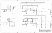
...3 AP1 4 AN2 5 AP2 6 7 CLK1- 8 CLK1+ 9 AN3 10 AP3 11 AN4 12 AP4 13 14 AN5 15 AP5 16 17 AN6 18 AP6 19 CLK2- 20 CLK2+ 21 AN7 22 AP7 23 3 24 25 26 27 LVDSVDD 28 LVDSVDD 29 30 + CE87 220uF/16v + CE88 220uF/16v CB185 0.1uF CB186 0.1uF...75 1% C151 C152 33pF 33pF 8x1 W/HOUSING DIP8/W/H/P2.54 GND B R281 75 1% B L78 0.082uH L/IND/SMD/0603 C154 33pF C155 33pF BLU_OUT GND C 1 Title LCD TV - CLK1+ 3 CLK1- 3 CLK2+ CLK2- MediaTek MT8205 Solution Size Doc Number B LVDS/CRT OUT Rev V0.1 Date: Tuesday, May 10, 2005 Sheet 14 of 16 D...
...3 AP1 4 AN2 5 AP2 6 7 CLK1- 8 CLK1+ 9 AN3 10 AP3 11 AN4 12 AP4 13 14 AN5 15 AP5 16 17 AN6 18 AP6 19 CLK2- 20 CLK2+ 21 AN7 22 AP7 23 3 24 25 26 27 LVDSVDD 28 LVDSVDD 29 30 + CE87 220uF/16v + CE88 220uF/16v CB185 0.1uF CB186 0.1uF...75 1% C151 C152 33pF 33pF 8x1 W/HOUSING DIP8/W/H/P2.54 GND B R281 75 1% B L78 0.082uH L/IND/SMD/0603 C154 33pF C155 33pF BLU_OUT GND C 1 Title LCD TV - CLK1+ 3 CLK1- 3 CLK2+ CLK2- MediaTek MT8205 Solution Size Doc Number B LVDS/CRT OUT Rev V0.1 Date: Tuesday, May 10, 2005 Sheet 14 of 16 D...

Service Manual
Page 21
... Q2 2N3906 3 2 510 510 DV33A 5VSB OBO0 L81 OBO1 L82 OBO2 L83 POWER OONB/OO3FF L84 OBO4 L85 OBO5 L86 LED_RED LED_GRN UP1_2 R81 0 FB TV/AV FB MENU FB VOLFB VOL+ FB CHFB CH+ IR R5I7R & P0 OWER ON LED J12 1 2 3 4 5 6 7 8 9 10 11 12 12x1 W/HOUSING DIP12/W/H/P2.0... Inverter_PWR PWR_GND L89 FB J11 1 2 3 4 5 6 7 8 9 10 10x1 W/HOUSING R.A. ANGLE 2 2 1 1 Title LCD TV - MediaTek MT8205 Solution Size Doc Number C BACK_LIGHT/KEYPAD Rev V0.1 Date: Tuesday, May 10, 2005 Sheet 15 of 16...
... Q2 2N3906 3 2 510 510 DV33A 5VSB OBO0 L81 OBO1 L82 OBO2 L83 POWER OONB/OO3FF L84 OBO4 L85 OBO5 L86 LED_RED LED_GRN UP1_2 R81 0 FB TV/AV FB MENU FB VOLFB VOL+ FB CHFB CH+ IR R5I7R & P0 OWER ON LED J12 1 2 3 4 5 6 7 8 9 10 11 12 12x1 W/HOUSING DIP12/W/H/P2.0... Inverter_PWR PWR_GND L89 FB J11 1 2 3 4 5 6 7 8 9 10 10x1 W/HOUSING R.A. ANGLE 2 2 1 1 Title LCD TV - MediaTek MT8205 Solution Size Doc Number C BACK_LIGHT/KEYPAD Rev V0.1 Date: Tuesday, May 10, 2005 Sheet 15 of 16...
Service Manual
Page 23
... 1 10uH 2 1 D3 MBRS130LTR C33 470NF FILM 2 C39 1 2 1000UF/25V 1 22 1 B R20 10 C35 100NF X7R A Title Size B Date: File: 5 Number Revision 2-Sep-2005 Sheet of D LCD TV\LCD TV.DdbDrawn By: 6
... 1 10uH 2 1 D3 MBRS130LTR C33 470NF FILM 2 C39 1 2 1000UF/25V 1 22 1 B R20 10 C35 100NF X7R A Title Size B Date: File: 5 Number Revision 2-Sep-2005 Sheet of D LCD TV\LCD TV.DdbDrawn By: 6

Service Manual
Page 25
... 1.6M C2 R3 C3 20K 100NF 35V 22U R24 10K Q2 BC337 R25 20R C20 50V 22UF Q3 BC327 STTH3L06 1 L3 2 D3 NTC1 400UH 3 PQ32-20 4 STTH8R06 2.5R R13 R6 68K $0.28 8 VCC 2 C6 25V 1U C5 680NF 1 R8 36K D2 1N4148 750K R14 750K Q1 R11 ZCD 5 STP20NM50 INV GND... 1K COMP STP12NK80 1 2 C10 5 6 TR1 ?? PQ3220 R36 OPEN C27 OPEN 12 +24V4A 10 11 +12V 8 9 +24V1A 7 12 +24V4A 10 11 +12V 8 9 +24V1A 7 GND 16 STBY 6 5 7 2 4 LCD-TV 200W SMPS SPEC: 1. +5V 2. +5VS 3. +12V 4.+24V 5. +24VA 4A 1A (Standby 5V) 2A 4A 1A 6.8K R29 C25 R34 R35 5.6K C24 3.3N C26 0.47R...
... 1.6M C2 R3 C3 20K 100NF 35V 22U R24 10K Q2 BC337 R25 20R C20 50V 22UF Q3 BC327 STTH3L06 1 L3 2 D3 NTC1 400UH 3 PQ32-20 4 STTH8R06 2.5R R13 R6 68K $0.28 8 VCC 2 C6 25V 1U C5 680NF 1 R8 36K D2 1N4148 750K R14 750K Q1 R11 ZCD 5 STP20NM50 INV GND... 1K COMP STP12NK80 1 2 C10 5 6 TR1 ?? PQ3220 R36 OPEN C27 OPEN 12 +24V4A 10 11 +12V 8 9 +24V1A 7 12 +24V4A 10 11 +12V 8 9 +24V1A 7 GND 16 STBY 6 5 7 2 4 LCD-TV 200W SMPS SPEC: 1. +5V 2. +5VS 3. +12V 4.+24V 5. +24VA 4A 1A (Standby 5V) 2A 4A 1A 6.8K R29 C25 R34 R35 5.6K C24 3.3N C26 0.47R...

Service Manual
Page 28
Disassembly In case of trouble,etc.Necessitating disassemble,please disassemble in the order shown in the illustrations. 1.Removal of the Back Cover. 2.Removal of AC cord from PCB;pull up the LCD PCB from The picture tube.To avaid a shock hazard,be sure to discharge. c.Remove the A node cap from LCD. d.Take out the LCD chassis. 27 b.slide out the LCD chassis slightly;pull up the connector of the MAIN PCB. a.Remove the screws.
Disassembly In case of trouble,etc.Necessitating disassemble,please disassemble in the order shown in the illustrations. 1.Removal of the Back Cover. 2.Removal of AC cord from PCB;pull up the LCD PCB from The picture tube.To avaid a shock hazard,be sure to discharge. c.Remove the A node cap from LCD. d.Take out the LCD chassis. 27 b.slide out the LCD chassis slightly;pull up the connector of the MAIN PCB. a.Remove the screws.

Service Manual
Page 30
Spare Part List for LCT2016 Item Part Number 1 TI-L20160001-01 2 TI-L20160002-01 3 TI-L20160003-01 4 TI-L20160004-01 5 TI-L20160005-01 6 TI-L20160006-01 7 TI-L20160007-01 8 TI-...-01 15 TI-L20160015-01 16 TI-L20160016-01 17 TI-L20160017-01 18 TI-L20160018-01 19 TI-L20160019-01 20 TI-L20160020-01 Part Description Usage Unit / unit 20.1" LCD Panel 1 piece Front Plastic Cabinet with Remote 1 piece Lens Plastic Back Cover with wall 1 piece mount bracket Plastic Base Cover 1 piece...
Spare Part List for LCT2016 Item Part Number 1 TI-L20160001-01 2 TI-L20160002-01 3 TI-L20160003-01 4 TI-L20160004-01 5 TI-L20160005-01 6 TI-L20160006-01 7 TI-L20160007-01 8 TI-...-01 15 TI-L20160015-01 16 TI-L20160016-01 17 TI-L20160017-01 18 TI-L20160018-01 19 TI-L20160019-01 20 TI-L20160020-01 Part Description Usage Unit / unit 20.1" LCD Panel 1 piece Front Plastic Cabinet with Remote 1 piece Lens Plastic Back Cover with wall 1 piece mount bracket Plastic Base Cover 1 piece...
Service Manual
Page 32
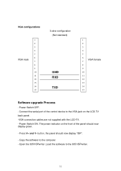
... TXD 1 2 3 4 5 6 VGA female 7 8 9 10 11 12 13 14 15 Software upgrade Process - Power Switch ON. The power indicator on the LCD-TV back panel. -VGA connection cables are not supplied with the LCD-TV. - Copy the software to the VGA jack on the front of the control device to the computer. - Open the 8051ISPwriter...
... TXD 1 2 3 4 5 6 VGA female 7 8 9 10 11 12 13 14 15 Software upgrade Process - Power Switch ON. The power indicator on the LCD-TV back panel. -VGA connection cables are not supplied with the LCD-TV. - Copy the software to the VGA jack on the front of the control device to the computer. - Open the 8051ISPwriter...