
Owners Manual English
Page 3
... 1 SERVICE CARE 2 ACCESSORIES 3 INSTALLATION 3 ATTACHING THE LOGO PLATE 3 CONNECTIONS 4 CONNECTION CHECK LIST 7 SWITCH SETTINGS 8 SYSTEM DIAGRAMS 12 SPECIFICATIONS 21 WARNING Points to contact, damage or obstruct pipes, fuel lines, tanks or electrical wiring. DO NOT ALLOW CABLES TO BECOME ENTANGLED IN SURROUNDING OBJECTS. When drilling holes in this manual. WARNING This symbol means important instructions. Always stop . LISTENING AT LOUD VOLUME LEVELS IN A CAR...
... 1 SERVICE CARE 2 ACCESSORIES 3 INSTALLATION 3 ATTACHING THE LOGO PLATE 3 CONNECTIONS 4 CONNECTION CHECK LIST 7 SWITCH SETTINGS 8 SYSTEM DIAGRAMS 12 SPECIFICATIONS 21 WARNING Points to contact, damage or obstruct pipes, fuel lines, tanks or electrical wiring. DO NOT ALLOW CABLES TO BECOME ENTANGLED IN SURROUNDING OBJECTS. When drilling holes in this manual. WARNING This symbol means important instructions. Always stop . LISTENING AT LOUD VOLUME LEVELS IN A CAR...

Owners Manual English
Page 4
.... For European Customers Should you purchased this unit requires special technical skill and experience. DO NOT USE BOLTS OR NUTS IN THE BRAKE OR STEERING SYSTEMS TO MAKE GROUND CONNECTIONS. Using such parts could disable control of moisture or dust. If swallowed, consult a physician immediately. HALT USE IMMEDIATELY IF A PROBLEM APPEARS. HAVE THE WIRING AND INSTALLATION DONE BY EXPERTS. USE SPECIFIED ACCESSORY PARTS AND INSTALL THEM SECURELY. The...
.... For European Customers Should you purchased this unit requires special technical skill and experience. DO NOT USE BOLTS OR NUTS IN THE BRAKE OR STEERING SYSTEMS TO MAKE GROUND CONNECTIONS. Using such parts could disable control of moisture or dust. If swallowed, consult a physician immediately. HALT USE IMMEDIATELY IF A PROBLEM APPEARS. HAVE THE WIRING AND INSTALLATION DONE BY EXPERTS. USE SPECIFIED ACCESSORY PARTS AND INSTALL THEM SECURELY. The...

Owners Manual English
Page 5
... Wrench (Large/Small 1 SET The Logo Plate is in operation. For alternate installation locations, please contact your desired direction. R-A60F) 3-EN Peel the Logo Plate along with four self-tapping screws. For this unit in a location which will allow for free circulation of the amplifier with...Plate is temporarily affixed to the high power output of the R-A75M/R-A60F considerable heat is produced when the amplifier is temporarily affixed to the bottom of air, such as a template, mark the four screw locations. 3. Make sure there are no objects behind ...
... Wrench (Large/Small 1 SET The Logo Plate is in operation. For alternate installation locations, please contact your desired direction. R-A60F) 3-EN Peel the Logo Plate along with four self-tapping screws. For this unit in a location which will allow for free circulation of the amplifier with...Plate is temporarily affixed to the high power output of the R-A75M/R-A60F considerable heat is produced when the amplifier is temporarily affixed to the bottom of air, such as a template, mark the four screw locations. 3. Make sure there are no objects behind ...

Owners Manual English
Page 6
... audio components. For details on the fuse capacity of the vehicle's chassis. • If you add an optional noise suppressor, connect it as far away from the unit as possible. *4 To securely connect the ground lead, use the wire of the amplifier. R-A75M R-A60F *1 *3, 4 Vehicle's chassis External Fuse*2 Vehicle's battery *1 External Fuse*2 *3, 4 Vehicle's chassis Vehicle's battery *1 For details on the wires size to be sure to turn...
... audio components. For details on the fuse capacity of the vehicle's chassis. • If you add an optional noise suppressor, connect it as far away from the unit as possible. *4 To securely connect the ground lead, use the wire of the amplifier. R-A75M R-A60F *1 *3, 4 Vehicle's chassis External Fuse*2 Vehicle's battery *1 External Fuse*2 *3, 4 Vehicle's chassis Vehicle's battery *1 For details on the wires size to be sure to turn...

Owners Manual English
Page 7
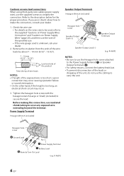
... unit using the Hexagon hole screw of the specified size. 5-EN Power Supply Terminal Connect the Battery Lead ( ), Remote Turn-on Lead ( ), and Ground Lead ( ) using RCA extension cables or Speaker-RCA Conversion cable (sold separately). Be sure to negative. This is an ideal output for appropriate fuse value requirement: R-A75M 80 amp fuse R-A60F 60 amp fuse • For details on the wires size to be used , refer to the supplied "Cautions on Power...
... unit using the Hexagon hole screw of the specified size. 5-EN Power Supply Terminal Connect the Battery Lead ( ), Remote Turn-on Lead ( ), and Ground Lead ( ) using RCA extension cables or Speaker-RCA Conversion cable (sold separately). Be sure to negative. This is an ideal output for appropriate fuse value requirement: R-A75M 80 amp fuse R-A60F 60 amp fuse • For details on the wires size to be used , refer to the supplied "Cautions on Power...
Owners Manual English
Page 8
... exposed wire is too short, a poor connection may occur. 3. Before making this connection, consult your dealer. 2. Hexagon hole screw Ground Lead Power Supply Terminal Battery Lead Remote Turn-On Lead (e.g. Cautions on Power Supply Wires" (page 20), and then use the wire of the specified size. • If the wire gauge used , refer to the supplied "Cautions on Power Supply Wires Connection" and "Cautions on wire lead connections When using third-party wire cables (power supply wire), use the...
... exposed wire is too short, a poor connection may occur. 3. Before making this connection, consult your dealer. 2. Hexagon hole screw Ground Lead Power Supply Terminal Battery Lead Remote Turn-On Lead (e.g. Cautions on Power Supply Wires" (page 20), and then use the wire of the specified size. • If the wire gauge used , refer to the supplied "Cautions on Power Supply Wires Connection" and "Cautions on wire lead connections When using third-party wire cables (power supply wire), use the...

Owners Manual English
Page 9
... unit's power antenna lead is activated only when the radio is on (and off when the vehicle is accessible by the driver. Make sure the switch is turned off ) the R-A75M/RA60F. Using this ignition tap. Blue/White Power Antenna Remote Turn-On Lead To other equipment in the tape or CD Mode). If this is logic level output (+) 5 V, negative trigger (grounding type), or cannot sustain (+) 12 V when connected to other Alpine...
... unit's power antenna lead is activated only when the radio is on (and off when the vehicle is accessible by the driver. Make sure the switch is turned off ) the R-A75M/RA60F. Using this ignition tap. Blue/White Power Antenna Remote Turn-On Lead To other equipment in the tape or CD Mode). If this is logic level output (+) 5 V, negative trigger (grounding type), or cannot sustain (+) 12 V when connected to other Alpine...

Owners Manual English
Page 10
R-A75M (Front Side) R-A60F (Rear Side) (Front Side) (Rear Side) 8-EN SWITCH SETTINGS • Before switching each Selector Switch, turn off the power and insert a small screwdriver, etc., perpendicularly to the Switch.
R-A75M (Front Side) R-A60F (Rear Side) (Front Side) (Rear Side) 8-EN SWITCH SETTINGS • Before switching each Selector Switch, turn off the power and insert a small screwdriver, etc., perpendicularly to the Switch.

Owners Manual English
Page 11
... volume 1 step (or until the output is desirable for driving full range speakers or when using an external electronic crossover. Crossover Frequency Adjustment Knob (LP FILTER) (R-A75M only) Use this setting, Crossover Frequency Adjustment Knob ( ) provides adjustment between 50 Hz to 6 kHz. This is no longer distorted). b) When making a speaker input connection with RCA Extension Cables (sold separately), set to drive a tweeter system. Crossover Mode Selector Switch (CHANNEL-1/2) (R-A60F only) a) Set...
... volume 1 step (or until the output is desirable for driving full range speakers or when using an external electronic crossover. Crossover Frequency Adjustment Knob (LP FILTER) (R-A75M only) Use this setting, Crossover Frequency Adjustment Knob ( ) provides adjustment between 50 Hz to 6 kHz. This is no longer distorted). b) When making a speaker input connection with RCA Extension Cables (sold separately), set to drive a tweeter system. Crossover Mode Selector Switch (CHANNEL-1/2) (R-A60F only) a) Set...

Owners Manual English
Page 12
... this control to adjust the crossover frequency between 50 Hz to 400 Hz. NOTES: • When the Crossover Mode Selector Switch ( ) is set to [BP], adjust the Crossover Frequency Adjustment Knob ( ) and ( ). • When the Crossover Mode Selector Switch ( ) is set to [HP] or [LP], adjustment of the Crossover Frequency Adjustment Knob ( ) is used for driving full range speakers or when using an external electronic crossover...
... this control to adjust the crossover frequency between 50 Hz to 400 Hz. NOTES: • When the Crossover Mode Selector Switch ( ) is set to [BP], adjust the Crossover Frequency Adjustment Knob ( ) and ( ). • When the Crossover Mode Selector Switch ( ) is set to [HP] or [LP], adjustment of the Crossover Frequency Adjustment Knob ( ) is used for driving full range speakers or when using an external electronic crossover...

Owners Manual English
Page 13
... Power Indicator Power Indicator Lights up when power is on the unit and verify that the indicator color has changed to a normal level. Is off when power is off the power supply and eliminate the cause. Indication color Blue Red (blinking) Red Status Amplifier circuit is abnormal. Use the correct power supply voltage. Amplifier circuit is normal. Solution Turn down the volume of the head unit (input signal). The indicator color changes...
... Power Indicator Power Indicator Lights up when power is on the unit and verify that the indicator color has changed to a normal level. Is off when power is off the power supply and eliminate the cause. Indication color Blue Red (blinking) Red Status Amplifier circuit is abnormal. Use the correct power supply voltage. Amplifier circuit is normal. Solution Turn down the volume of the head unit (input signal). The indicator color changes...

Owners Manual English
Page 14
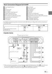
... R-A75M Power Supply Terminal Fuse RCA Input Jacks Pre-Out Jacks Remote Bass Control (optional) Speaker Output Terminals Battery Lead (sold separately) Remote Turn-On Lead (sold separately) Ground Lead (sold separately) Front Speakers (Tweeter) Front Speakers (Midrange) 12-EN SYSTEM DIAGRAMS Before making a connection, check the total number of impedance of the speaker connected to the unit. If you have any questions, contact the nearest Alpine dealer. Front Output Rear Output Subwoofer Output Front Speakers Rear Speaker Subwoofer Dual Voice Coil Subwoofer RCA Extension Cable...
... R-A75M Power Supply Terminal Fuse RCA Input Jacks Pre-Out Jacks Remote Bass Control (optional) Speaker Output Terminals Battery Lead (sold separately) Remote Turn-On Lead (sold separately) Ground Lead (sold separately) Front Speakers (Tweeter) Front Speakers (Midrange) 12-EN SYSTEM DIAGRAMS Before making a connection, check the total number of impedance of the speaker connected to the unit. If you have any questions, contact the nearest Alpine dealer. Front Output Rear Output Subwoofer Output Front Speakers Rear Speaker Subwoofer Dual Voice Coil Subwoofer RCA Extension Cable...

Owners Manual English
Page 15
... Subwoofer System, make sure that the minimum impedance exceeds 2 Ω in the SPECIFICATIONS (page 21) is the specification with the total impedance value. 13-EN Subwoofer System Speaker Input Level Switch [LO] Remote Turn-On Lead 1 Subwoofer System Head Unit, etc. 2 Subwoofer System (MONO) Dual Voice Coil Subwoofer System Parallel connection Series connection * If the connected head unit does not have a Speaker Output and RCA Extension Cable ( ) cannot be used, you can use the Speaker-RCA...
... Subwoofer System, make sure that the minimum impedance exceeds 2 Ω in the SPECIFICATIONS (page 21) is the specification with the total impedance value. 13-EN Subwoofer System Speaker Input Level Switch [LO] Remote Turn-On Lead 1 Subwoofer System Head Unit, etc. 2 Subwoofer System (MONO) Dual Voice Coil Subwoofer System Parallel connection Series connection * If the connected head unit does not have a Speaker Output and RCA Extension Cable ( ) cannot be used, you can use the Speaker-RCA...
Owners Manual English
Page 16
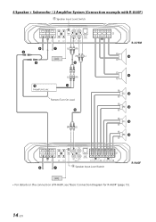
4 Speaker + Subwoofer / 2 Amplifier System (Connection example with R-A60F) Speaker Input Level Switch R-A75M [LO] Head Unit, etc. Remote Turn-On Lead Speaker Input Level Switch R-A60F [LO] • For details on the connection of R-A60F, see "Basic Connection Diagram for R-A60F" (page 15). 14-EN
4 Speaker + Subwoofer / 2 Amplifier System (Connection example with R-A60F) Speaker Input Level Switch R-A75M [LO] Head Unit, etc. Remote Turn-On Lead Speaker Input Level Switch R-A60F [LO] • For details on the connection of R-A60F, see "Basic Connection Diagram for R-A60F" (page 15). 14-EN
Owners Manual English
Page 17
... Subwoofer RCA Extension Cable (sold separately) Speaker-RCA Conversion Cable (sold separately) Y-Adapter (sold separately) Front Speakers (Tweeter) Front Speakers (Midrange) For R-A60F, change the Input Channel Selector Switch ( ) setting according to the Speaker Input Level System" (page 19). 15-EN For details on how to make a connection, see "About Connecting to the number of channels of the speaker input. Basic Connection Diagram for R-A60F Power Supply Terminal Fuse RCA Input Jacks Pre-Out Jacks Remote Bass Control (optional) Speaker Output Terminals Battery...
... Subwoofer RCA Extension Cable (sold separately) Speaker-RCA Conversion Cable (sold separately) Y-Adapter (sold separately) Front Speakers (Tweeter) Front Speakers (Midrange) For R-A60F, change the Input Channel Selector Switch ( ) setting according to the Speaker Input Level System" (page 19). 15-EN For details on how to make a connection, see "About Connecting to the number of channels of the speaker input. Basic Connection Diagram for R-A60F Power Supply Terminal Fuse RCA Input Jacks Pre-Out Jacks Remote Bass Control (optional) Speaker Output Terminals Battery...

Owners Manual English
Page 18
2 Speaker + Subwoofer System (Bridged Connections) Speaker Input Level Switch [LO] Remote Turn-On Lead Head Unit, etc. 2 Speaker System (Bridged Connections) Speaker Input Level Switch [LO] Remote Turn-On Lead Head Unit, etc. 16-EN
2 Speaker + Subwoofer System (Bridged Connections) Speaker Input Level Switch [LO] Remote Turn-On Lead Head Unit, etc. 2 Speaker System (Bridged Connections) Speaker Input Level Switch [LO] Remote Turn-On Lead Head Unit, etc. 16-EN

Owners Manual English
Page 19
Crossover Mode Selector Switch (CHANNEL-1/2) HP-H Input Channel Selector Switch (CHANNEL-3/4) 3/4 Crossover Mode Selector Switch (CHANNEL-3/4) BP Speaker Input Level Switch [LO] Remote Turn-On Lead Head Unit, etc. 17-EN Front 2-Way System When using the Front 2-Way System, set each switch as follows.
Crossover Mode Selector Switch (CHANNEL-1/2) HP-H Input Channel Selector Switch (CHANNEL-3/4) 3/4 Crossover Mode Selector Switch (CHANNEL-3/4) BP Speaker Input Level Switch [LO] Remote Turn-On Lead Head Unit, etc. 17-EN Front 2-Way System When using the Front 2-Way System, set each switch as follows.

Owners Manual English
Page 20
Front 2-Way + Subwoofer / 2 Amplifier System (Connection example with R-A75M) When using the Front 2-Way + Subwoofer / 2 Amplifier System, set each switch as follows. Crossover Mode Selector Switch (CHANNEL-1/2) HP-H Input Channel Selector Switch (CHANNEL-3/4) 1/2 Crossover Mode Selector Switch (CHANNEL-3/4) BP Speaker Input Level Switch R-A75M [LO] Head Unit, etc. Remote Turn-On Lead 18-EN Speaker Input Level Switch [LO] R-A60F
Front 2-Way + Subwoofer / 2 Amplifier System (Connection example with R-A75M) When using the Front 2-Way + Subwoofer / 2 Amplifier System, set each switch as follows. Crossover Mode Selector Switch (CHANNEL-1/2) HP-H Input Channel Selector Switch (CHANNEL-3/4) 1/2 Crossover Mode Selector Switch (CHANNEL-3/4) BP Speaker Input Level Switch R-A75M [LO] Head Unit, etc. Remote Turn-On Lead 18-EN Speaker Input Level Switch [LO] R-A60F

Owners Manual English
Page 21
... Connecting to the Speaker Input Level System When connecting by using the Speaker-RCA Conversion Cable ( ) (sold separately), switch the Speaker Input Level Switch ( ) to an incoming power supply cord (accessory power) in the ACC position. In such a case, connect the Remote Turn-On Lead to "HI". The Y-adapter is not required if a stereo/mono pair line output is used to drive both inputs of this unit. e.g. One signal Head Unit, etc. Important Tips on the signal source connected. One signal...
... Connecting to the Speaker Input Level System When connecting by using the Speaker-RCA Conversion Cable ( ) (sold separately), switch the Speaker Input Level Switch ( ) to an incoming power supply cord (accessory power) in the ACC position. In such a case, connect the Remote Turn-On Lead to "HI". The Y-adapter is not required if a stereo/mono pair line output is used to drive both inputs of this unit. e.g. One signal Head Unit, etc. Important Tips on the signal source connected. One signal...

Owners Manual English
Page 22
...; External Fuse capacity: Make it equal to or larger than total fuse capacity of the number of amplifiers installed 80 A + 80 A + 60 A = equal to or larger than one amplifier, a distribution block should be used , refer to the supplied "Cautions on Power Supply Wires Connection" and the following connection example. For details on Power Supply Wires Use the specified wire size according to the total fuse capacity of the power and ground cables...
...; External Fuse capacity: Make it equal to or larger than total fuse capacity of the number of amplifiers installed 80 A + 80 A + 60 A = equal to or larger than one amplifier, a distribution block should be used , refer to the supplied "Cautions on Power Supply Wires Connection" and the following connection example. For details on Power Supply Wires Use the specified wire size according to the total fuse capacity of the power and ground cables...


