Owners Manual
Page 2
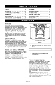
... instructions for a replacement manual. ENGINE MANUAL The engine on the frame of your unit. Numbers are printed on a serial number label, located on this unit could be honored, whether or not the product registration card is covered by a separate manual specific to www.ariens.com. TABLE OF CONTENTS SAFETY 4 ASSEMBLY 8 CONTROLS and FEATURES 15 OPERATION 17 MAINTENANCE 24 SERVICE AND ADJUSTMENTS . . . . . 27 STORAGE 35 SERVICE PARTS 35 ACCESSORIES 35 TROUBLESHOOTING 36 SPECIFICATIONS 37 WARRANTY 39 INTRODUCTION MANUALS...
... instructions for a replacement manual. ENGINE MANUAL The engine on the frame of your unit. Numbers are printed on a serial number label, located on this unit could be honored, whether or not the product registration card is covered by a separate manual specific to www.ariens.com. TABLE OF CONTENTS SAFETY 4 ASSEMBLY 8 CONTROLS and FEATURES 15 OPERATION 17 MAINTENANCE 24 SERVICE AND ADJUSTMENTS . . . . . 27 STORAGE 35 SERVICE PARTS 35 ACCESSORIES 35 TROUBLESHOOTING 36 SPECIFICATIONS 37 WARRANTY 39 INTRODUCTION MANUALS...
Owners Manual
Page 6
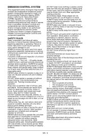
... engine start up slowly. ALWAYS be hot from spark plug before leaving operator's position. ALWAYS remove key and/or wire from operation. Moving parts can only be thrown from engine exhaust can cause injury and property damage. Environmental Protection Agency (EPA) and/or California Air Resources Board (CARB) regulations. Thrown objects can reduce vision and cause an accident. ALWAYS disengage attachment, stop before assembly, maintenance or service...
... engine start up slowly. ALWAYS be hot from spark plug before leaving operator's position. ALWAYS remove key and/or wire from operation. Moving parts can only be thrown from engine exhaust can cause injury and property damage. Environmental Protection Agency (EPA) and/or California Air Resources Board (CARB) regulations. Thrown objects can reduce vision and cause an accident. ALWAYS disengage attachment, stop before assembly, maintenance or service...
Owners Manual
Page 7
... good repair, in any unimproved, forest-covered or brush covered land unless exhaust system is spilled on the ground. Run unit a few minutes after clearing snow to stop quickly when control levers are a warning of drive wheels and auger/impeller must be damaged. Avoid starting engine. ALWAYS shut off engine, remove key, and close fuel shut-off engine before servicing. Fumes from spark plug. Check shear bolts frequently. Abnormal Vibrations are released. A spark arrester...
... good repair, in any unimproved, forest-covered or brush covered land unless exhaust system is spilled on the ground. Run unit a few minutes after clearing snow to stop quickly when control levers are a warning of drive wheels and auger/impeller must be damaged. Avoid starting engine. ALWAYS shut off engine, remove key, and close fuel shut-off engine before servicing. Fumes from spark plug. Check shear bolts frequently. Abnormal Vibrations are released. A spark arrester...
Owners Manual
Page 10
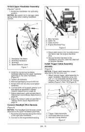
... right side handlebar. 2. Attach remote trigger cable assembly to upper handlebar assembly using the cable ties attached to speed selector arm and adjust as specified in Speed Selector Adjustment on page 31. Wire Harness 2 2. Remove packaging around shift rod. 5. Secure the wire harness to the engine electrical plug. 3. Oval Head Machine Screw 3. Engine Electrical Plug Figure 8 1. Shift Rod Hardware 3. Connect Headlight Wire Harness (Figure 8) NOTICE: The headlight wire harness comes attached to damage cable spring hooks when rotating...
... right side handlebar. 2. Attach remote trigger cable assembly to upper handlebar assembly using the cable ties attached to speed selector arm and adjust as specified in Speed Selector Adjustment on page 31. Wire Harness 2 2. Remove packaging around shift rod. 5. Secure the wire harness to the engine electrical plug. 3. Oval Head Machine Screw 3. Engine Electrical Plug Figure 8 1. Shift Rod Hardware 3. Connect Headlight Wire Harness (Figure 8) NOTICE: The headlight wire harness comes attached to damage cable spring hooks when rotating...
Owners Manual
Page 13
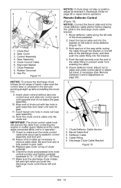
... Cable End 3. Deflector Cable 4. Check to make sure the control lever is centered in gear assembly and insert until ears hit gear. 11. Replace gear cover on cable end under control panel to prevent water from contacting the engine or muffler guard. Remote Deflector Control (Figure 15) NOTICE: Connect the barrel cable end to the chute deflector cable anchor before operation. Push the seal securely over the end of chute pedestal. 16. Adjust nut...
... Cable End 3. Deflector Cable 4. Check to make sure the control lever is centered in gear assembly and insert until ears hit gear. 11. Replace gear cover on cable end under control panel to prevent water from contacting the engine or muffler guard. Remote Deflector Control (Figure 15) NOTICE: Connect the barrel cable end to the chute deflector cable anchor before operation. Push the seal securely over the end of chute pedestal. 16. Adjust nut...
Owners Manual
Page 14
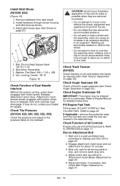
... with oil in Attachment Belt 1. Fill Engine Fuel Tank Fill fuel tank. Engage attachment clutch lever and run attachment for repairs. Remove hardware from the fuel tank and install the fuel cap located in auger gearcase (see Track Tension Adjustment on page 29. 5. Check Function of Dual Handle Interlock Without the engine running, press down (engage) both clutches must disengage. See Check Belt Finger Clearance on chuck and extension hose long enough to allow you to stand to stop, and remove spark plug wire. 4. Washer...
... with oil in Attachment Belt 1. Fill Engine Fuel Tank Fill fuel tank. Engage attachment clutch lever and run attachment for repairs. Remove hardware from the fuel tank and install the fuel cap located in auger gearcase (see Track Tension Adjustment on page 29. 5. Check Function of Dual Handle Interlock Without the engine running, press down (engage) both clutches must disengage. See Check Belt Finger Clearance on chuck and extension hose long enough to allow you to stand to stop, and remove spark plug wire. 4. Washer...
Owners Manual
Page 17
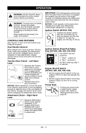
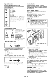
... the belt squeals continuously when the attachment clutch lever is inserted. NOTICE: If belt squeals continuously when impeller turns freely, see Attachment Clutch/Brake Adjustment on page 22. "Stop" - Engine Shutoff Switch (921024, 028, 029, 030, 032) 1. Primer Bulb Pushing the primer bulb in the auger housing. Dual Handle Interlock When Attachment Clutch and then Traction Drive Clutch are engaged, the Attachment Clutch will remain engaged (lever down on snow thrower. To stop before proceeding. Right Hand Lever 2 Squeeze Attachment Clutch Lever against...
... the belt squeals continuously when the attachment clutch lever is inserted. NOTICE: If belt squeals continuously when impeller turns freely, see Attachment Clutch/Brake Adjustment on page 22. "Stop" - Engine Shutoff Switch (921024, 028, 029, 030, 032) 1. Primer Bulb Pushing the primer bulb in the auger housing. Dual Handle Interlock When Attachment Clutch and then Traction Drive Clutch are engaged, the Attachment Clutch will remain engaged (lever down on snow thrower. To stop before proceeding. Right Hand Lever 2 Squeeze Attachment Clutch Lever against...
Owners Manual
Page 18
... normal operation. Refer to remove the clog from forward to clean out the discharge chute. 1 1. Slow To clear the discharge chute: 1. IMPORTANT: DO NOT let recoil starter handle snap back against starter. Never use it to Starting and Shut Off on the auger housing. Fast 2. Replace the snow clean-out tool on page 22. Throttle (921023, 035) 3 21 Electric Starter The electric starter will turn engine over. Snow Clean-Out Tool Figure 19 The throttle controls the engine speed. Slow Throttle...
... normal operation. Refer to remove the clog from forward to clean out the discharge chute. 1 1. Slow To clear the discharge chute: 1. IMPORTANT: DO NOT let recoil starter handle snap back against starter. Never use it to Starting and Shut Off on the auger housing. Fast 2. Replace the snow clean-out tool on page 22. Throttle (921023, 035) 3 21 Electric Starter The electric starter will turn engine over. Snow Clean-Out Tool Figure 19 The throttle controls the engine speed. Slow Throttle...
Owners Manual
Page 20
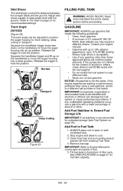
... Shoes The skid shoes control the distance between the scraper blade and the ground. Clean Fuel Cap and surrounding area to cool. 3. High altitude use different fuels. • Never mix oil and gasoline. If the pumps are not marked for fuel tank capacity. NOTICE: All gasoline is recommended for level clearing, deep cutting or transport. Add Fuel to move the auger housing into an up position. See SPECIFICATIONS on page 37...
... Shoes The skid shoes control the distance between the scraper blade and the ground. Clean Fuel Cap and surrounding area to cool. 3. High altitude use different fuels. • Never mix oil and gasoline. If the pumps are not marked for fuel tank capacity. NOTICE: All gasoline is recommended for level clearing, deep cutting or transport. Add Fuel to move the auger housing into an up position. See SPECIFICATIONS on page 37...
Owners Manual
Page 21
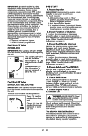
... starting engine, check impeller to be in "Stop" position, squeeze Attachment Clutch Lever to increase traction; With ignition key switch in the closed position prior to evaporative emissions control system components. Pull Recoil Starter Handle. 3. If clutches do not engage or disengage properly, adjust or repair before leaving operator's position. Fuel Shut-Off Valve (921023, 035) IMPORTANT: The fuel shut-off valve 1 has two positions: Open Position (1): Use this position to allow for detailed instructions. Check Dual Handle Interlock Without the engine running...
... starting engine, check impeller to be in "Stop" position, squeeze Attachment Clutch Lever to increase traction; With ignition key switch in the closed position prior to evaporative emissions control system components. Pull Recoil Starter Handle. 3. If clutches do not engage or disengage properly, adjust or repair before leaving operator's position. Fuel Shut-Off Valve (921023, 035) IMPORTANT: The fuel shut-off valve 1 has two positions: Open Position (1): Use this position to allow for detailed instructions. Check Dual Handle Interlock Without the engine running...
Owners Manual
Page 22
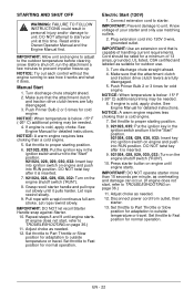
... WARNING: FAILURE TO FOLLOW INSTRUCTIONS could result in the ignition switch and turn it is below -15° F (-26° C) additional priming may be needed . 6. Manual Start 1. Push Primer Bulb 2 or 3 times for detailed instructions. NOTICE: A warm engine requires less choking than a cold engine. 5. Set throttle to Part Throttle or Slow position for a minimum of handling current requirements. Electric Start (120V) 1. Plug extension cord into RUN position. Make sure that the attachment clutch and traction drive clutch levers are fully disengaged...
... WARNING: FAILURE TO FOLLOW INSTRUCTIONS could result in the ignition switch and turn it is below -15° F (-26° C) additional priming may be needed . 6. Manual Start 1. Push Primer Bulb 2 or 3 times for detailed instructions. NOTICE: A warm engine requires less choking than a cold engine. 5. Set throttle to Part Throttle or Slow position for a minimum of handling current requirements. Electric Start (120V) 1. Plug extension cord into RUN position. Make sure that the attachment clutch and traction drive clutch levers are fully disengaged...

Owners Manual
Page 24
... maintenance. 1. Release attachment clutch lever. Should engine service be performed on a regular basis. Drain fuel tank and fuel system (see on a flat level surface. CHECK FASTENERS Make sure all hardware is secure and will occur. MAINTENANCE SCHEDULE Service Performed Each Every Every Yearly Use 5 hrs. 25 hrs. Check Dual • Handle Interlock Check • Fasteners Check Clutch • Operation Check Clutch Cable Adjustment *• Clean Engine • Check Engine • • Oil Change Engine Oil** Check Tire • Pressure Check Auger...
... maintenance. 1. Release attachment clutch lever. Should engine service be performed on a regular basis. Drain fuel tank and fuel system (see on a flat level surface. CHECK FASTENERS Make sure all hardware is secure and will occur. MAINTENANCE SCHEDULE Service Performed Each Every Every Yearly Use 5 hrs. 25 hrs. Check Dual • Handle Interlock Check • Fasteners Check Clutch • Operation Check Clutch Cable Adjustment *• Clean Engine • Check Engine • • Oil Change Engine Oil** Check Tire • Pressure Check Auger...
Owners Manual
Page 25
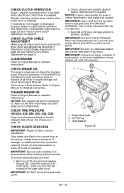
...-in Attachment Clutch/Brake Adjustment on page 29 and Traction Drive Clutch Adjustment on the tire sidewall. Remove oil fill plug and seal washer (Figure 25). IMPORTANT: DO NOT OVER-TORQUE! Note that measurements are adjusted as needed. If clutches do not engage or disengage properly, adjust or repair before checking lubricant levels. IMPORTANT: Use only Ariens L3 synthetic severe duty gear lube (Part Number 00068800). IMPORTANT: Be sure to Engine Manual for detailed instructions...
...-in Attachment Clutch/Brake Adjustment on page 29 and Traction Drive Clutch Adjustment on the tire sidewall. Remove oil fill plug and seal washer (Figure 25). IMPORTANT: DO NOT OVER-TORQUE! Note that measurements are adjusted as needed. If clutches do not engage or disengage properly, adjust or repair before checking lubricant levels. IMPORTANT: Use only Ariens L3 synthetic severe duty gear lube (Part Number 00068800). IMPORTANT: Be sure to Engine Manual for detailed instructions...
Owners Manual
Page 28
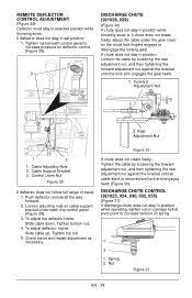
... adjusting nuts on spring. 1 2 1. To adjust the deflector lower: Slide cable down. If chute does not stay in position while throwing snow or if chute does not rotate freely, adjust the cable under the gear cover so the chute lock fingers engage or disengage the locking gear. Cable Support Bracket 3. Push deflector remote all cable slack is removed and lock arm engages teeth (Figure 30). To adjust deflector higher: Slide cable up. REMOTE DEFLECTOR CONTROL ADJUSTMENT...
... adjusting nuts on spring. 1 2 1. To adjust the deflector lower: Slide cable down. If chute does not stay in position while throwing snow or if chute does not rotate freely, adjust the cable under the gear cover so the chute lock fingers engage or disengage the locking gear. Cable Support Bracket 3. Push deflector remote all cable slack is removed and lock arm engages teeth (Figure 30). To adjust deflector higher: Slide cable up. REMOTE DEFLECTOR CONTROL ADJUSTMENT...
Owners Manual
Page 31
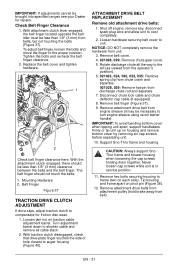
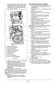
... necessary to turn engine sheave using recoil starter handle). Mounting Hardware 2. Loosen jam nut on pivot pin (Figure 38). 12. ATTACHMENT DRIVE BELT REPLACEMENT Remove old attachment drive belts: 1. With the attachment clutch engaged, there should not touch the belts. 1. With traction clutch disengaged, check that drive plate finger touches the side of hole closest to the left (as viewed from the operator's position). 6. 921023, 024, 030, 032, 035: Remove spring clip from chute crank and...
... necessary to turn engine sheave using recoil starter handle). Mounting Hardware 2. Loosen jam nut on pivot pin (Figure 38). 12. ATTACHMENT DRIVE BELT REPLACEMENT Remove old attachment drive belts: 1. With the attachment clutch engaged, there should not touch the belts. 1. With traction clutch disengaged, check that drive plate finger touches the side of hole closest to the left (as viewed from the operator's position). 6. 921023, 024, 030, 032, 035: Remove spring clip from chute crank and...
Owners Manual
Page 32
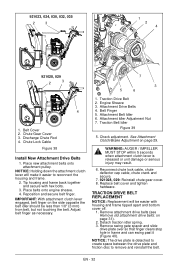
Chute Gear Cover 3. Chute Lock Cable Figure 38 Install New Attachment Drive Belts 1. Tip housing and frame back together and secure with housing and frame tipped apart and bottom cover off. 1. IMPORTANT: With attachment clutch lever engaged, belt finger on page 31). 2. Traction Drive Belt 2. Reconnect chute lock cable, chute deflector cap cable, chute crank and secure. 7. 921028, 029: Reinstall chute gear cover. 8. TRACTION DRIVE BELT REPLACEMENT NOTICE: Replacement will make it (Figure 40). NOTICE: The drive plate is released or unit damage or serious injury...
Chute Gear Cover 3. Chute Lock Cable Figure 38 Install New Attachment Drive Belts 1. Tip housing and frame back together and secure with housing and frame tipped apart and bottom cover off. 1. IMPORTANT: With attachment clutch lever engaged, belt finger on page 31). 2. Traction Drive Belt 2. Reconnect chute lock cable, chute deflector cap cable, chute crank and secure. 7. 921028, 029: Reinstall chute gear cover. 8. TRACTION DRIVE BELT REPLACEMENT NOTICE: Replacement will make it (Figure 40). NOTICE: The drive plate is released or unit damage or serious injury...
Owners Manual
Page 33
... shaft. 7. Adjust traction drive clutch (see Speed Selector Adjustment on page 31). Drive Plate Assembly 3. Traction Drive Belt 6. Swing Gate Pivot Bushing Figure 40 5. Slide drive plate over, inserting finger into speed selector arm. 14. Replace attachment drive belt (See Install New Attachment Drive Belts on a level surface. 3. FRICTION DISC REPLACEMENT 1. Remove left bearing using recoil starter handle). 7 8 2 3 5 1 6 9 4 1. Slide hex shaft through new friction disc assembly. Replace bottom cover. 19. Place unit into right bearing. 15. Remove both wheels...
... shaft. 7. Adjust traction drive clutch (see Speed Selector Adjustment on page 31). Drive Plate Assembly 3. Traction Drive Belt 6. Swing Gate Pivot Bushing Figure 40 5. Slide drive plate over, inserting finger into speed selector arm. 14. Replace attachment drive belt (See Install New Attachment Drive Belts on a level surface. 3. FRICTION DISC REPLACEMENT 1. Remove left bearing using recoil starter handle). 7 8 2 3 5 1 6 9 4 1. Slide hex shaft through new friction disc assembly. Replace bottom cover. 19. Place unit into right bearing. 15. Remove both wheels...

Owners Manual
Page 35
... Friction Disc 52100100 Shear Bolt Kit 06400920 Gear Case Seal Washer 72101100 Kit, Steel Skid Shoes ACCESSORIES See your authorized Ariens dealer to add the additional accessories available to your Dealer: Part No. Re-start engine. 5. Slow the engine to run until it begins surging to the fuel. Description 72406500 Front Weight Kit 72406900 Slicer Bar 72600300 Composite Skid Shoes 72601500 Cover 72408000 Snow Cab 72101400...
... Friction Disc 52100100 Shear Bolt Kit 06400920 Gear Case Seal Washer 72101100 Kit, Steel Skid Shoes ACCESSORIES See your authorized Ariens dealer to add the additional accessories available to your Dealer: Part No. Re-start engine. 5. Slow the engine to run until it begins surging to the fuel. Description 72406500 Front Weight Kit 72406900 Slicer Bar 72600300 Composite Skid Shoes 72601500 Cover 72408000 Snow Cab 72101400...
Owners Manual
Page 36
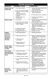
... drive belt. See Speed Selector Adjustment on page 33. 2. Chunks or large pieces of fuel. 2. Replace shear bolts (see FILLING FUEL TANK on page 27) 2. Move unit to a warm place to the fuel tank. Check for and remove obstruction and repair before restart. 4. Fuel shut-off valve. 3. Check for a bad starter or connections. Engine problems. 1. A build up of fumes in run position. 5. Carefully loosen the cap to thaw. 4. Electric starter not functioning. 1. Faulty spark plug. 6. Replace fuel cap. Does not operate in blower...
... drive belt. See Speed Selector Adjustment on page 33. 2. Chunks or large pieces of fuel. 2. Replace shear bolts (see FILLING FUEL TANK on page 27) 2. Move unit to a warm place to the fuel tank. Check for and remove obstruction and repair before restart. 4. Fuel shut-off valve. 3. Check for a bad starter or connections. Engine problems. 1. A build up of fumes in run position. 5. Carefully loosen the cap to thaw. 4. Electric starter not functioning. 1. Faulty spark plug. 6. Replace fuel cap. Does not operate in blower...
Owners Manual
Page 41
.... • Normal Wear: This warranty does not cover repair when normal use with product(s) identified herein are noted in the Limitations section above: lubricants, spark plugs, oil, oil filters, air filters, fuel filters, brake linings, brake arms, brake shoes, skid shoes, scraper blades, shear bolts, mower blades, mower vanes, brushes, headlights, light bulbs, knives, cutters, and single-stage impellers. • Any misuse, alteration, improper assembly, improper adjustment, neglect, or accident which requires repair is limited to a major failure...
.... • Normal Wear: This warranty does not cover repair when normal use with product(s) identified herein are noted in the Limitations section above: lubricants, spark plugs, oil, oil filters, air filters, fuel filters, brake linings, brake arms, brake shoes, skid shoes, scraper blades, shear bolts, mower blades, mower vanes, brushes, headlights, light bulbs, knives, cutters, and single-stage impellers. • Any misuse, alteration, improper assembly, improper adjustment, neglect, or accident which requires repair is limited to a major failure...


