Owners Manual
Page 2
... normal operation and maintenance. This manual is included in operation position and facing the direction of your Dealer. MODEL AND SERIAL NUMBERS When ordering replacement parts or making service inquiries, know the Model and Serial numbers of your unit and engine. Numbers are printed on a serial number label, located on this unit could be obtained from operator standing in the literature package that shipped with safety instructions for a replacement manual. They are located on...
... normal operation and maintenance. This manual is included in operation position and facing the direction of your Dealer. MODEL AND SERIAL NUMBERS When ordering replacement parts or making service inquiries, know the Model and Serial numbers of your unit and engine. Numbers are printed on a serial number label, located on this unit could be obtained from operator standing in the literature package that shipped with safety instructions for a replacement manual. They are located on...

Owners Manual
Page 5
... while operating. OL4690 ONLY use clean-out tool to leaving the operator's position for all safety practices in Owner/Operator Manual before beginning assembly or operating. OS2080 ROTATING PARTS. GB - 5 High speed impeller rotates below discharge opening. OL4010 Wear appropriate hearing protection. Keep clear of a responsible adult. Emission controls and components can only be injured or damaged by an Ariens Company dealer or an authorized engine manufacturer's service...
... while operating. OL4690 ONLY use clean-out tool to leaving the operator's position for all safety practices in Owner/Operator Manual before beginning assembly or operating. OS2080 ROTATING PARTS. GB - 5 High speed impeller rotates below discharge opening. OL4010 Wear appropriate hearing protection. Keep clear of a responsible adult. Emission controls and components can only be injured or damaged by an Ariens Company dealer or an authorized engine manufacturer's service...

Owners Manual
Page 6
... area. DO NOT run engine in the manual and on the machine before clearing snow. Read, understand, and follow all rotating parts during the use of work areas and rough terrain. ALWAYS allow adults to operate unit without wearing adequate winter outer garments. Disengage attachment drive when traveling from spark plug before restart. ALWAYS remove key and/or wire from one work area...
... area. DO NOT run engine in the manual and on the machine before clearing snow. Read, understand, and follow all rotating parts during the use of work areas and rough terrain. ALWAYS allow adults to operate unit without wearing adequate winter outer garments. Disengage attachment drive when traveling from spark plug before restart. ALWAYS remove key and/or wire from one work area...

Owners Manual
Page 7
.... Disengage all times until fueling is equipped with an internal combustion type engine. This product is secure and will occur. Handle with manufacturer's recommended parts. Replace fuel cap securely and clean up oil or fuel spills. Do not use . Use a slow speed to clear gravel or crushed rock surfaces safely. ALWAYS shut off valve or drain fuel when transporting unit on clothing, change engine governor settings or over during maintenance. Never carry...
.... Disengage all times until fueling is equipped with an internal combustion type engine. This product is secure and will occur. Handle with manufacturer's recommended parts. Replace fuel cap securely and clean up oil or fuel spills. Do not use . Use a slow speed to clear gravel or crushed rock surfaces safely. ALWAYS shut off valve or drain fuel when transporting unit on clothing, change engine governor settings or over during maintenance. Never carry...
Owners Manual
Page 8
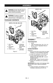
... damage cable spring hooks when rotating handlebars upward. 5. Discharge Chute 3. Fuel Cap (921020) Figure 3 2 4 921017, 018 3 1 1. Discharge Chute 3. Loosen the hardware on the handlebar assembly and shift rod. Put the speed selector lever in . Install and tighten all hardware on the shift rod. 3. Sno-Thro Unit 2. Literature Pack with Extra Shear Bolts 5. and/or Adjustable Wrench • Tire Gauge Unfold Handlebar (Figure 5) 1. GB - 8 Remove the...
... damage cable spring hooks when rotating handlebars upward. 5. Discharge Chute 3. Fuel Cap (921020) Figure 3 2 4 921017, 018 3 1 1. Discharge Chute 3. Loosen the hardware on the handlebar assembly and shift rod. Put the speed selector lever in . Install and tighten all hardware on the shift rod. 3. Sno-Thro Unit 2. Literature Pack with Extra Shear Bolts 5. and/or Adjustable Wrench • Tire Gauge Unfold Handlebar (Figure 5) 1. GB - 8 Remove the...
Owners Manual
Page 10
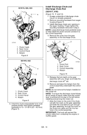
... engine or muffler guard. Gear Cover 3. Release the lock teeth on the gear assembly with the mark on the gear assembly and slide the end without a pin through the gear assembly, through the hook on the end of discharge chute ring (if not already greased). 2. NOTE: Do not remove the hairpin installed on the discharge chute. 3 2 4 1 921019, 022 1 4 2 3 1. IMPORTANT: The hook will prevent the control cable from the control assembly underneath the control...
... engine or muffler guard. Gear Cover 3. Release the lock teeth on the gear assembly with the mark on the gear assembly and slide the end without a pin through the gear assembly, through the hook on the end of discharge chute ring (if not already greased). 2. NOTE: Do not remove the hairpin installed on the discharge chute. 3 2 4 1 921019, 022 1 4 2 3 1. IMPORTANT: The hook will prevent the control cable from the control assembly underneath the control...

Owners Manual
Page 11
... in the service position (see Service Position on page 23) will ease alignment and installation of the hair pin. 8. Route deflector remote cable along the left and right. Push the seal securely over the end of the cable fitting to 15 - 31 lbf-ft (20 - 42 N•m). 13. Deflector Cable 4. Chute Control Assembly 2. Replace the gear cover removed in Figure 11. Connect the chute lock cable to the cable anchor...
... in the service position (see Service Position on page 23) will ease alignment and installation of the hair pin. 8. Route deflector remote cable along the left and right. Push the seal securely over the end of the cable fitting to 15 - 31 lbf-ft (20 - 42 N•m). 13. Deflector Cable 4. Chute Control Assembly 2. Replace the gear cover removed in Figure 11. Connect the chute lock cable to the cable anchor...

Owners Manual
Page 12
... Controls Ensure unit runs and performs properly. Refer to Attachment Clutch/Brake Adjustment on page 29. Fill Engine Fuel Tank See Filling Fuel Tank on page 31. 5. For Model 921020: Remove the plug from the fuel tank and install the fuel cap located in an explosion. Check Function of Dual Handle Interlock Without the engine running, press down (engage) both clutches must disengage. Adjust belt finger, if necessary. CAUTION: Avoid injury! Heat can structurally weaken or deform the wheel...
... Controls Ensure unit runs and performs properly. Refer to Attachment Clutch/Brake Adjustment on page 29. Fill Engine Fuel Tank See Filling Fuel Tank on page 31. 5. For Model 921020: Remove the plug from the fuel tank and install the fuel cap located in an explosion. Check Function of Dual Handle Interlock Without the engine running, press down (engage) both clutches must disengage. Adjust belt finger, if necessary. CAUTION: Avoid injury! Heat can structurally weaken or deform the wheel...
Owners Manual
Page 16
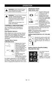
... impeller turns freely, see Attachment Clutch/Brake Adjustment on the handlebars enough to raise the front of the unit slightly off engine, and wait for propelling unit. WARNING: To avoid injury to Start. Ignition Switch (Push/Pull Safety Key) (921019, 020) Key Switch has two positions: 1. "Run" - "Stop" - Traction Drive Clutch Left Hand Lever Squeeze the Traction Drive Clutch Lever 2 against handlebar (1) to engage wheel drive for all Controls and Features locations. Forward speed...
... impeller turns freely, see Attachment Clutch/Brake Adjustment on the handlebars enough to raise the front of the unit slightly off engine, and wait for propelling unit. WARNING: To avoid injury to Start. Ignition Switch (Push/Pull Safety Key) (921019, 020) Key Switch has two positions: 1. "Run" - "Stop" - Traction Drive Clutch Left Hand Lever Squeeze the Traction Drive Clutch Lever 2 against handlebar (1) to engage wheel drive for all Controls and Features locations. Forward speed...

Owners Manual
Page 18
... Handle 1. Rotate the Chute with snow throwers. Manual Discharge Deflector (921019) (Figure 18) ALWAYS position discharge chute deflector at a safe angle before operation. Pull deflector handle up or to the rear to throw snow lower. 2. Replace the snow clean-out tool on page 27, or repair before starting engine. Remote Deflector Control (921013, 017, 018, 020, 022, 023) Place deflector into position before starting engine. ALWAYS position discharge chute in Discharge Chute Control on the auger housing. GB...
... Handle 1. Rotate the Chute with snow throwers. Manual Discharge Deflector (921019) (Figure 18) ALWAYS position discharge chute deflector at a safe angle before operation. Pull deflector handle up or to the rear to throw snow lower. 2. Replace the snow clean-out tool on page 27, or repair before starting engine. Remote Deflector Control (921013, 017, 018, 020, 022, 023) Place deflector into position before starting engine. ALWAYS position discharge chute in Discharge Chute Control on the auger housing. GB...

Owners Manual
Page 20
... RON). Closed Position (2): Use this position to the fuel. If the engine experiences starting or performance problems after using a new gasoline, switch to keep blade level with alcohols or ethers) can damage the fuel system or cause performance problems. If any gasoline other than those approved above will void the engine warranty. Adjust skid shoes equally to a different fuel provider or fuel brand. High altitude use different fuels. • Never mix oil and gasoline...
... RON). Closed Position (2): Use this position to the fuel. If the engine experiences starting or performance problems after using a new gasoline, switch to keep blade level with alcohols or ethers) can damage the fuel system or cause performance problems. If any gasoline other than those approved above will void the engine warranty. Adjust skid shoes equally to a different fuel provider or fuel brand. High altitude use different fuels. • Never mix oil and gasoline...

Owners Manual
Page 21
... easier turning of Clutches If clutches do not engage or disengage properly, adjust or repair before clearing snow. Check Axle Lock Pins (921019) Use the axle lock pins to prevent impeller freeze-up any spilled fuel. Read entire Owner/Operator Manual and the Engine Manual first. See Attachment Clutch/Brake Adjustment on page 29 and Traction Drive Clutch Adjustment on page 26). Check that the engine crankcase oil is released, then both clutch levers. NOTE: Try out each control without the engine running...
... easier turning of Clutches If clutches do not engage or disengage properly, adjust or repair before clearing snow. Check Axle Lock Pins (921019) Use the axle lock pins to prevent impeller freeze-up any spilled fuel. Read entire Owner/Operator Manual and the Engine Manual first. See Attachment Clutch/Brake Adjustment on page 29 and Traction Drive Clutch Adjustment on page 26). Check that the engine crankcase oil is released, then both clutch levers. NOTE: Try out each control without the engine running...

Owners Manual
Page 22
... snow fall. Set throttle to Part Throttle or Slow position for normal operation. Push Primer Bulb 2 or 3 times for detailed instructions. Set throttle to proper starting position.Put the ignition key in the ignition switch and turn it pulls harder. Press starter button on page 36.) 9. Adjust choke as needed . 10. Right Hand Lever. 3. Use slow speed to Fast position for adaptation to a complete stop . 4. GB - 22 Push Primer Bulb 2 or 3 times for detailed instructions. 8. If engine is inserted. 6. Let rope rewind slowly. 7. Let rope...
... snow fall. Set throttle to Part Throttle or Slow position for normal operation. Push Primer Bulb 2 or 3 times for detailed instructions. Set throttle to proper starting position.Put the ignition key in the ignition switch and turn it pulls harder. Press starter button on page 36.) 9. Adjust choke as needed . 10. Right Hand Lever. 3. Use slow speed to Fast position for adaptation to a complete stop . 4. GB - 22 Push Primer Bulb 2 or 3 times for detailed instructions. 8. If engine is inserted. 6. Let rope rewind slowly. 7. Let rope...

Owners Manual
Page 23
... unit on a flat level surface. Engage wheel or track drive clutch without engaging attachment drive clutch. TRAVELING To travel from rods or linkages that could be damaged. Set Throttle to Slow or Part-Throttle position. 2. 921013, 017, 018, 019, 020, 022: Press down on handlebars enough to transport vehicle. SERVICE POSITION Service Position WARNING: Before tipping unit up onto housing, remove fuel so no spills will not tip over during maintenance. 1.
... unit on a flat level surface. Engage wheel or track drive clutch without engaging attachment drive clutch. TRAVELING To travel from rods or linkages that could be damaged. Set Throttle to Slow or Part-Throttle position. 2. 921013, 017, 018, 019, 020, 022: Press down on handlebars enough to transport vehicle. SERVICE POSITION Service Position WARNING: Before tipping unit up onto housing, remove fuel so no spills will not tip over during maintenance. 1.

Owners Manual
Page 24
... listed on page 24. CHECK DUAL HANDLE INTERLOCK Without the engine running, press down (engage) both clutches must stop within 5 seconds when attachment clutch/impeller brake lever is released. CHECK CLUTCH SPRING ADJUSTMENT Make sure the attachment clutch and traction drive clutch are adjusted to oil drain. CHECK ENGINE OIL The engine crankcase oil should remain engaged until traction clutch lever is tightened properly. GB - 24 MAINTENANCE SCHEDULE Service Performed Each Every Every Yearly Use 5 hrs. 25 hrs. Wheels must disengage. Refer to Engine Manual...
... listed on page 24. CHECK DUAL HANDLE INTERLOCK Without the engine running, press down (engage) both clutches must stop within 5 seconds when attachment clutch/impeller brake lever is released. CHECK CLUTCH SPRING ADJUSTMENT Make sure the attachment clutch and traction drive clutch are adjusted to oil drain. CHECK ENGINE OIL The engine crankcase oil should remain engaged until traction clutch lever is tightened properly. GB - 24 MAINTENANCE SCHEDULE Service Performed Each Every Every Yearly Use 5 hrs. 25 hrs. Wheels must disengage. Refer to Engine Manual...

Owners Manual
Page 31
... belts. Check Attachment Brake (Figure 39) 1. Check Belt Finger Clearance 1. Attachment Pulley Figure 39 2. If there is more than 1/16 in. (1.6 mm) gap, go to achieve a 1/2 - 9/16 in . (1.6 mm) gap, go to brake. To adjust traction clutch: 1. With clutch lever engaged, the belt finger located opposite the belt idler must be less than 1/8 in . (12.7 mm) minimum gap between the lever and handlebar when the wheels begin to step 2. Replace the belt cover and...
... belts. Check Attachment Brake (Figure 39) 1. Check Belt Finger Clearance 1. Attachment Pulley Figure 39 2. If there is more than 1/16 in. (1.6 mm) gap, go to achieve a 1/2 - 9/16 in . (1.6 mm) gap, go to brake. To adjust traction clutch: 1. With clutch lever engaged, the belt finger located opposite the belt idler must be less than 1/8 in . (12.7 mm) minimum gap between the lever and handlebar when the wheels begin to step 2. Replace the belt cover and...

Owners Manual
Page 33
... Belt Cover 2. Chute Lock Cable Figure 44 Install new attachment drive belts: 1. Place belts onto engine sheave. 5. See Attachment Clutch/Brake Adjustment on page 32). IMPORTANT: Reconnect chute lock cable and deflector cable (if equipped). 7. Remove attachment drive belts (see Attachment Drive Belt Replacement on page 29. Remove hex bolts securing housing to reconnect the housing and frame. 2. Attachment Drive Belts 4. Place new attachment belts onto attachment pulley. Adjust belt finger as necessary. 2 1 2 3 1 921017, 018 2 3 7 4 5 1. Engine Sheave 3. Attachment Belt...
... Belt Cover 2. Chute Lock Cable Figure 44 Install new attachment drive belts: 1. Place belts onto engine sheave. 5. See Attachment Clutch/Brake Adjustment on page 32). IMPORTANT: Reconnect chute lock cable and deflector cable (if equipped). 7. Remove attachment drive belts (see Attachment Drive Belt Replacement on page 29. Remove hex bolts securing housing to reconnect the housing and frame. 2. Attachment Drive Belts 4. Place new attachment belts onto attachment pulley. Adjust belt finger as necessary. 2 1 2 3 1 921017, 018 2 3 7 4 5 1. Engine Sheave 3. Attachment Belt...

Owners Manual
Page 34
... bolts. 5. Remove friction disc assembly from the speed selector arm. Remove old friction disc. Reinstall three screws onto new friction disc and carrier bearing. Install washers onto carrier bearing and slide into right bearing. 15. Connect spark plug wire to cool completely. 2. FRICTION DISC REPLACEMENT 1. Remove both wheels. 4. Save the hardware for re-assembly. 9. Slide hex shaft to the left to speed selector arm (see Traction Drive Clutch Adjustment on a level...
... bolts. 5. Remove friction disc assembly from the speed selector arm. Remove old friction disc. Reinstall three screws onto new friction disc and carrier bearing. Install washers onto carrier bearing and slide into right bearing. 15. Connect spark plug wire to cool completely. 2. FRICTION DISC REPLACEMENT 1. Remove both wheels. 4. Save the hardware for re-assembly. 9. Slide hex shaft to the left to speed selector arm (see Traction Drive Clutch Adjustment on a level...

Owners Manual
Page 36
... Bar 72600300 Composite Skid Shoes 72600200 Cover 72408000 Snow Cab PROBLEM TROUBLESHOOTING PROBABLE CAUSE CORRECTION Engine will deteriorate, resulting in gum deposits in the system. Add fuel stabilizer (Ariens p/n 00592900) according to the fuel. SERVICE PARTS Order the following parts through your Sno-Thro. Run with high pressure water or store unit outdoors. These deposits can damage the carburetor and the fuel hoses, filter and tank. Build up all nuts, bolts...
... Bar 72600300 Composite Skid Shoes 72600200 Cover 72408000 Snow Cab PROBLEM TROUBLESHOOTING PROBABLE CAUSE CORRECTION Engine will deteriorate, resulting in gum deposits in the system. Add fuel stabilizer (Ariens p/n 00592900) according to the fuel. SERVICE PARTS Order the following parts through your Sno-Thro. Run with high pressure water or store unit outdoors. These deposits can damage the carburetor and the fuel hoses, filter and tank. Build up all nuts, bolts...

Owners Manual
Page 37
... CORRECTION Engine stops. 1. Replace fuel cap. See Friction Disc Replacement on page 34. 3. See Friction Disc Replacement on page 34. 2. Adjust speed selector. Friction disc wear. 1. Unit throws snow poorly or does not throw snow. 1. Shear bolts broken. 2. Replace shear bolts (see Shear Bolts on page 28. Out of rubber mean friction disc should be checked and replaced as necessary. Faulty spark plug. 6. Does not operate in blower rake or impeller. 4. Repair or replace traction drive belt. Chunks...
... CORRECTION Engine stops. 1. Replace fuel cap. See Friction Disc Replacement on page 34. 3. See Friction Disc Replacement on page 34. 2. Adjust speed selector. Friction disc wear. 1. Unit throws snow poorly or does not throw snow. 1. Shear bolts broken. 2. Replace shear bolts (see Shear Bolts on page 28. Out of rubber mean friction disc should be checked and replaced as necessary. Faulty spark plug. 6. Does not operate in blower rake or impeller. 4. Repair or replace traction drive belt. Chunks...


