Owners Manual
Page 5
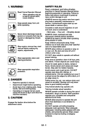
...clothing away. • Operating on or near drop-offs, ditches, or embankments. Engage the traction drive before operation. Unintentional engine start up can reduce vision and cause an accident. DO NOT allow adults to operate unit without wearing adequate outer garments. Keep area ... only by thrown objects. DANGER! • Read the operator's manual. • Adjust brush height before beginning assembly or operating. SAFETY RULES Read, understand, and follow instructions could cause the brush to unit. Failure to improve footing on docks, ramps or floors. Complete a walk around...
...clothing away. • Operating on or near drop-offs, ditches, or embankments. Engage the traction drive before operation. Unintentional engine start up can reduce vision and cause an accident. DO NOT allow adults to operate unit without wearing adequate outer garments. Keep area ... only by thrown objects. DANGER! • Read the operator's manual. • Adjust brush height before beginning assembly or operating. SAFETY RULES Read, understand, and follow instructions could cause the brush to unit. Failure to improve footing on docks, ramps or floors. Complete a walk around...
Owners Manual
Page 6
... a three-wire grounded system. Allow parts to cool before restart. Read, understand, and follow all controls. • How to stop before starting engine, disengage control(s). Understand: • How to stop unit and engine. Abnormal vibrations are a warning of slopes. Before cleaning, removing clogs...unit parts which might be injured or damaged by attempting to cool. Inspect unit and make sudden changes in an emergency. Adjust brush height before attachment clutch. ALWAYS back up oil or fuel spills. Use extra care when loading or unloading unit onto trailer ...
... a three-wire grounded system. Allow parts to cool before restart. Read, understand, and follow all controls. • How to stop before starting engine, disengage control(s). Understand: • How to stop unit and engine. Abnormal vibrations are a warning of slopes. Before cleaning, removing clogs...unit parts which might be injured or damaged by attempting to cool. Inspect unit and make sudden changes in an emergency. Adjust brush height before attachment clutch. ALWAYS back up oil or fuel spills. Use extra care when loading or unloading unit onto trailer ...
Owners Manual
Page 8
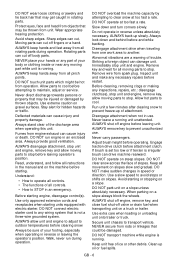
.... GB - 8 Loosen the hardware on page 10. Welding can cause an increase in air pressure resulting in a well-ventilated area according to Starting and Shut Off on chuck and extension hose long enough to allow you to stand to unit. Check Engine Crankcase Oil IMPORTANT: Engine is possible... Unfold Handlebar (Figure 3) 1. Use a clip-on page 13. 2. Fill Engine Fuel Tank Refer to Engine Manual for proper fuel type and tank capacity. Start unit in an explosion. Heat can structurally weaken or deform the wheel. • Do not stand in front or over boxed unit could result in...
.... GB - 8 Loosen the hardware on page 10. Welding can cause an increase in air pressure resulting in a well-ventilated area according to Starting and Shut Off on chuck and extension hose long enough to allow you to stand to unit. Check Engine Crankcase Oil IMPORTANT: Engine is possible... Unfold Handlebar (Figure 3) 1. Use a clip-on page 13. 2. Fill Engine Fuel Tank Refer to Engine Manual for proper fuel type and tank capacity. Start unit in an explosion. Heat can structurally weaken or deform the wheel. • Do not stand in front or over boxed unit could result in...
Owners Manual
Page 9
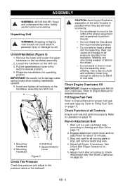
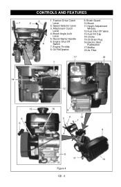
CONTROLS AND FEATURES 1 3 2 1. Brush Angle Lock 13.Fuel Fill Cap Lever 14.Choke 5. Engine Shut Off 4 Switch 16.Electric Start Pushbutton 7. Traction Drive Clutch Lever 9. Attachment Clutch Wheels Lever 12.Fuel Shut Off Valve 4. Oil Fill/Dipstick 18.Air Filter 17 18 7 14 12 13 6 5 16 8 32 15 1 9 4 8 11 10 15 Figure 4 GB - 9 Recoil Starter Handle 15.Oil Drain Plug 6. Engine Throttle 17.Muffler 8. Speed Selector Lever 11.Height Adjustment 3. Brush Guard 10.Brush 2.
CONTROLS AND FEATURES 1 3 2 1. Brush Angle Lock 13.Fuel Fill Cap Lever 14.Choke 5. Engine Shut Off 4 Switch 16.Electric Start Pushbutton 7. Traction Drive Clutch Lever 9. Attachment Clutch Wheels Lever 12.Fuel Shut Off Valve 4. Oil Fill/Dipstick 18.Air Filter 17 18 7 14 12 13 6 5 16 8 32 15 1 9 4 8 11 10 15 Figure 4 GB - 9 Recoil Starter Handle 15.Oil Drain Plug 6. Engine Throttle 17.Muffler 8. Speed Selector Lever 11.Height Adjustment 3. Brush Guard 10.Brush 2.
Owners Manual
Page 10
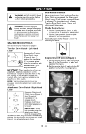
... Control Lever 1. Set the engine shut off air to brush. ON OFF Figure 5 GB - 10 STANDARD CONTROLS See Controls and Features on the handlebars enough to engage brush. Release clutch lever (2) to disengage power 1 to engine for all movement to shut off a running...front of the unit slightly off switch (Figure 4, item 6) to the On position to start . 2. OL2701 Release lever (2) to engage wheel drive for normal operation. IMPORTANT: When traveling to or from brush. Right Hand Lever Squeeze Attachment Clutch Lever (Figure 4, item 3) against the handlebar 1...
... Control Lever 1. Set the engine shut off air to brush. ON OFF Figure 5 GB - 10 STANDARD CONTROLS See Controls and Features on the handlebars enough to engage brush. Release clutch lever (2) to disengage power 1 to engine for all movement to shut off a running...front of the unit slightly off switch (Figure 4, item 6) to the On position to start . 2. OL2701 Release lever (2) to engage wheel drive for normal operation. IMPORTANT: When traveling to or from brush. Right Hand Lever Squeeze Attachment Clutch Lever (Figure 4, item 3) against the handlebar 1...
Owners Manual
Page 11
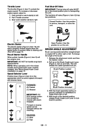
...will release the cable-operated lock pin. To change motion 4. With brush in the closed position prior to service, transport, or store the unit. 12 3 Electric Starter The electric starter (Figure 4, item 16) will start a properly choked engine when the starter button is pushed. Part-... throttle (Figure 4, item 7) controls the engine speed. Refer to Starting and Shut Off on handlebars to either right or left. Open Position: Use this position to transporting the unit. BRUSH ANGLE ADJUSTMENT Brush can be positioned either straight ahead or angled 20º to IMPORTANT...
...will release the cable-operated lock pin. To change motion 4. With brush in the closed position prior to service, transport, or store the unit. 12 3 Electric Starter The electric starter (Figure 4, item 16) will start a properly choked engine when the starter button is pushed. Part-... throttle (Figure 4, item 7) controls the engine speed. Refer to Starting and Shut Off on handlebars to either right or left. Open Position: Use this position to transporting the unit. BRUSH ANGLE ADJUSTMENT Brush can be positioned either straight ahead or angled 20º to IMPORTANT...
Owners Manual
Page 12
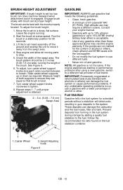
... attained. 2 - 3 in the fuel system during storage by adding a quality fuel stabilizer to the fuel. If the engine experiences starting or performance problems after using a new gasoline, switch to stop. 5. Start the brush at proper height. Follow the recommended mix ratio found on the fuel stabilizer container. 1 1. Fuel Stabilizer Gasoline left in the...
... attained. 2 - 3 in the fuel system during storage by adding a quality fuel stabilizer to the fuel. If the engine experiences starting or performance problems after using a new gasoline, switch to stop. 5. Start the brush at proper height. Follow the recommended mix ratio found on the fuel stabilizer container. 1 1. Fuel Stabilizer Gasoline left in the...
Owners Manual
Page 13
... must disengage. Remove cap. PRE-START 1.Check Function of Clutches Brush must stop before leaving operator's position. Attachment clutch should remain engaged until engine starts. (If engine does not start -up any service. 3. See Brush Angle Adjustment on page 11 and Brush Height Adjustment on page 19. 6..... If clutches do not engage or disengage properly, adjust or repair before operation (Service and Adjustments on page 19). 3.Adjust Brush Adjust brush height and angle before operation. NOTE: Try out each control without the engine running , press down (engage) both control levers...
... must disengage. Remove cap. PRE-START 1.Check Function of Clutches Brush must stop before leaving operator's position. Attachment clutch should remain engaged until engine starts. (If engine does not start -up any service. 3. See Brush Angle Adjustment on page 11 and Brush Height Adjustment on page 19. 6..... If clutches do not engage or disengage properly, adjust or repair before operation (Service and Adjustments on page 19). 3.Adjust Brush Adjust brush height and angle before operation. NOTE: Try out each control without the engine running , press down (engage) both control levers...
Owners Manual
Page 14
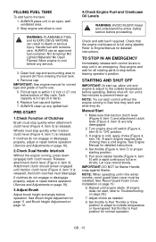
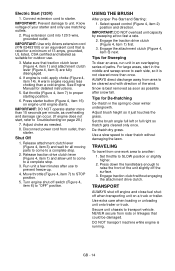
...lever (Figure 4, item 1) and allow unit to come to another: 1. USING THE BRUSH After proper Pre-Start and Starting: 1. ALWAYS direct discharge away from one work area to a complete stop . 3..... 6. Adjust brush height so it is not cleared more than a cold engine. Press down the handlebars enough to prevent freeze-up. 4. IMPORTANT: Use only Ariens extension cord (P/N 02483100) or an equivalent ...certified and labeled as needed. 8. Adjust choke as suitable for detailed instructions. 5. Disconnect power cord from rods or linkages that could be cleared and with direction of the wind....
...lever (Figure 4, item 1) and allow unit to come to another: 1. USING THE BRUSH After proper Pre-Start and Starting: 1. ALWAYS direct discharge away from one work area to a complete stop . 3..... 6. Adjust brush height so it is not cleared more than a cold engine. Press down the handlebars enough to prevent freeze-up. 4. IMPORTANT: Use only Ariens extension cord (P/N 02483100) or an equivalent ...certified and labeled as needed. 8. Adjust choke as suitable for detailed instructions. 5. Disconnect power cord from rods or linkages that could be cleared and with direction of the wind....
Owners Manual
Page 15
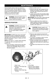
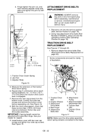
... belt fingers away from traction unit bottom cover (3). See Figure 12. Remove the brush if maintenance requires tipping the unit forward. WARNING: AVOID INJURY. Unintentional engine start up onto brush. Loosen four side cap screws (4) and remove bottom cover. 4. CAUTION: Always ... is secure and will provide any service or adjustments which may be required, contact an Ariens dealer or an authorized engine manufacturer's service center. To separate the brush attachment from traction unit. 1 7 6 2 5 4 3 4 1. Strap or clamp unit onto bench if required. See ...
... belt fingers away from traction unit bottom cover (3). See Figure 12. Remove the brush if maintenance requires tipping the unit forward. WARNING: AVOID INJURY. Unintentional engine start up onto brush. Loosen four side cap screws (4) and remove bottom cover. 4. CAUTION: Always ... is secure and will provide any service or adjustments which may be required, contact an Ariens dealer or an authorized engine manufacturer's service center. To separate the brush attachment from traction unit. 1 7 6 2 5 4 3 4 1. Strap or clamp unit onto bench if required. See ...
Owners Manual
Page 19
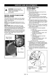
... guard and freezing the recoil pawls. Adjust pivot pin on page 17. The foam prevents snow from speed selector lever. 2. Check forward and reverse speeds: a. Start unit. NOTE: The recoil guard foam cover is in step 1. 1 Recoil Guard 4 Figure 9 3 2 1. Recoil Guard Foam Cover Velcro SPEED SELECTOR ADJUSTMENT To adjust (Figure 10...
... guard and freezing the recoil pawls. Adjust pivot pin on page 17. The foam prevents snow from speed selector lever. 2. Check forward and reverse speeds: a. Start unit. NOTE: The recoil guard foam cover is in step 1. 1 Recoil Guard 4 Figure 9 3 2 1. Recoil Guard Foam Cover Velcro SPEED SELECTOR ADJUSTMENT To adjust (Figure 10...
Owners Manual
Page 22
... body with pliers and tighten the jam nut with two rear cap screws and tighten four side cap screws See Figure 19. 8 2 3 5 9 OS7221 7 6 1. Unintentional engine start up can cause death or serious injury.
... body with pliers and tighten the jam nut with two rear cap screws and tighten four side cap screws See Figure 19. 8 2 3 5 9 OS7221 7 6 1. Unintentional engine start up can cause death or serious injury.

Owners Manual
Page 24
... before assembly, maintenance or service. NOTE: The gearbox at each side of the brush allows only half the brush segments to be removed from each bearing setscrew and slide bearings inward, away from brush assembly. Self-Tapping Screws 3. Unintentional engine start up can cause death or serious injury. 1. Place unit on one end. See...
... before assembly, maintenance or service. NOTE: The gearbox at each side of the brush allows only half the brush segments to be removed from each bearing setscrew and slide bearings inward, away from brush assembly. Self-Tapping Screws 3. Unintentional engine start up can cause death or serious injury. 1. Place unit on one end. See...
Owners Manual
Page 28
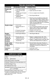
...your Dealer: Part No. GB - 28 TROUBLESHOOTING PROBLEM PROBABLE CAUSE CORRECTION Engine will not crank/start. 1. Engine shut off switch turned off valve closed. 3. Let recoil assembly dry completely before... stops. 1. Faulty spark plug. 1. Replace or clean spark plug. Does not operate in brush. 3. Repair or replace traction drive belt. See Service and Adjustments on page 17. U-joint... into a warm area and allow the recoil assembly to www.ariens.com. Out of 2) 21547200 Spark Plug 00170800 Friction Disc 00036800 Ariens Hi-Temp Grease (Three 3 oz. Mechanical jam in Forward/...
...your Dealer: Part No. GB - 28 TROUBLESHOOTING PROBLEM PROBABLE CAUSE CORRECTION Engine will not crank/start. 1. Engine shut off switch turned off valve closed. 3. Let recoil assembly dry completely before... stops. 1. Faulty spark plug. 1. Replace or clean spark plug. Does not operate in brush. 3. Repair or replace traction drive belt. See Service and Adjustments on page 17. U-joint... into a warm area and allow the recoil assembly to www.ariens.com. Out of 2) 21547200 Spark Plug 00170800 Friction Disc 00036800 Ariens Hi-Temp Grease (Three 3 oz. Mechanical jam in Forward/...


