

Owners Manual
Page 6
... cause injury or damage. Keep feet and hands away from unit while unit is attached. 2. To avoid dismemberment hazard do not put hands near rotating blades. GB - 6 DANGER! Keep all guards are in operating position or bagger is in place. 3.2 Discharge Hazard Discharge Hazard NEVER direct discharge toward people, pets or...
... cause injury or damage. Keep feet and hands away from unit while unit is attached. 2. To avoid dismemberment hazard do not put hands near rotating blades. GB - 6 DANGER! Keep all guards are in operating position or bagger is in place. 3.2 Discharge Hazard Discharge Hazard NEVER direct discharge toward people, pets or...
Owners Manual
Page 9
...'s recommendations for : missing or damaged decals and shields, correctly operating safety interlock system, and deterioration of steering control. NEVER carry passengers - especially children - even with blades off fingers or a hand. Operation on the ground. When operating on slopes be in operator's position. Mow up a slope or you can safely control and...
...'s recommendations for : missing or damaged decals and shields, correctly operating safety interlock system, and deterioration of steering control. NEVER carry passengers - especially children - even with blades off fingers or a hand. Operation on the ground. When operating on slopes be in operator's position. Mow up a slope or you can safely control and...

Owners Manual
Page 10
... positive (+) cable SECOND. DO NOT charge or jump start a battery containing frozen fluid. NEVER modify or remove safety devices. If tires lose traction, disengage the blades and proceed slowly straight down the slope. Travel slowly and allow extra distance to cause cancer and reproductive harm. NEVER secure from a gasoline dispenser nozzle...
... positive (+) cable SECOND. DO NOT charge or jump start a battery containing frozen fluid. NEVER modify or remove safety devices. If tires lose traction, disengage the blades and proceed slowly straight down the slope. Travel slowly and allow extra distance to cause cancer and reproductive harm. NEVER secure from a gasoline dispenser nozzle...
Owners Manual
Page 11
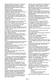
... hole of the other components from the shipping container. Slide steering lever back to align slot with the engine running. Wrap the blade(s) or wear gloves, and use extra caution when servicing them. Check brake operation frequently. Steering Lever Hardware Figure 3 GB -.... See storage section and Engine Manual for your unit. Unpack Unit Remove unit and all hardware properly tightened. NEVER weld or straighten mower blades. Disengage transmission bypass lever. NOTE: Do not tighten hardware before storing in the installation section. 1 3 2 1. If no adjustment is...
... hole of the other components from the shipping container. Slide steering lever back to align slot with the engine running. Wrap the blade(s) or wear gloves, and use extra caution when servicing them. Check brake operation frequently. Steering Lever Hardware Figure 3 GB -.... See storage section and Engine Manual for your unit. Unpack Unit Remove unit and all hardware properly tightened. NEVER weld or straighten mower blades. Disengage transmission bypass lever. NOTE: Do not tighten hardware before storing in the installation section. 1 3 2 1. If no adjustment is...
Owners Manual
Page 15
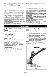
... to start the engine. Height of Cut (Figure 5) 1. Parking Brake Lever Engages (2) and disengages (1) parking 1 brake. 2 Power Take-Off (PTO) Switch Engages (2) and 1 disengages (1) mower blades. 2 NOTE: To stop, return both . 1. Release mower lift pedal. 2 3 1 Steering Levers • Reverse (1) - Pull left steering lever forward or a combination of both. • Right (4) - Use...
... to start the engine. Height of Cut (Figure 5) 1. Parking Brake Lever Engages (2) and disengages (1) parking 1 brake. 2 Power Take-Off (PTO) Switch Engages (2) and 1 disengages (1) mower blades. 2 NOTE: To stop, return both . 1. Release mower lift pedal. 2 3 1 Steering Levers • Reverse (1) - Pull left steering lever forward or a combination of both. • Right (4) - Use...
Owners Manual
Page 16
... 9). 3. Units equipped with water when the unit is warm from hose coupling onto top of wet grass clippings is attached to harmful thrown objects or blade contact. Water can result in the mower. 1. Release the lock collar to lock the coupling to the desired position. Turn the water supply on page...
... 9). 3. Units equipped with water when the unit is warm from hose coupling onto top of wet grass clippings is attached to harmful thrown objects or blade contact. Water can result in the mower. 1. Release the lock collar to lock the coupling to the desired position. Turn the water supply on page...

Owners Manual
Page 18
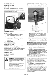
.... Clean after engine starts. The control arms will automatically return gradually to engage. IMPORTANT: DO NOT operate starter for the blades to neutral when released from the neutral lockout position. 4. Engine will not run smoothly and will smell like fuel if operating... parking brake must be prepared to react to starting the engine, gradually set parking brake. 3. Use steering levers to start mower blades. Keep mower blades sharp. See "Throttle/Choke Lever" on ambient temperature. If the engine is cold or the ambient temperature is dry. IMPORTANT: ...
.... Clean after engine starts. The control arms will automatically return gradually to engage. IMPORTANT: DO NOT operate starter for the blades to neutral when released from the neutral lockout position. 4. Engine will not run smoothly and will smell like fuel if operating... parking brake must be prepared to react to starting the engine, gradually set parking brake. 3. Use steering levers to start mower blades. Keep mower blades sharp. See "Throttle/Choke Lever" on ambient temperature. If the engine is cold or the ambient temperature is dry. IMPORTANT: ...
Owners Manual
Page 20
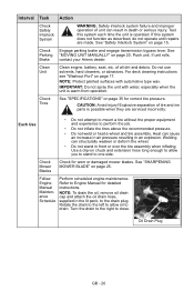
... tires above the recommended pressure. • Do not weld or heat a wheel and tire assembly. CAUTION: Avoid injury! Check Mower Blades Check for correct tire pressure. Follow Engine Manual Maintenance Schedule Perform scheduled engine maintenance. NOTE: To drain the oil, remove oil drain cap...a clip-on page 35 for worn or damaged mower blades. Clean Unit Clean engine, battery, seat, etc. See "SHARPENING MOWER BLADE" on page 20. See "Safety Interlock System" on page 17. If unit rolls, contact your Ariens dealer. Explosive separation of tire and rim parts is warm...
... tires above the recommended pressure. • Do not weld or heat a wheel and tire assembly. CAUTION: Avoid injury! Check Mower Blades Check for correct tire pressure. Follow Engine Manual Maintenance Schedule Perform scheduled engine maintenance. NOTE: To drain the oil, remove oil drain cap...a clip-on page 35 for worn or damaged mower blades. Clean Unit Clean engine, battery, seat, etc. See "SHARPENING MOWER BLADE" on page 20. See "Safety Interlock System" on page 17. If unit rolls, contact your Ariens dealer. Explosive separation of tire and rim parts is warm...

Owners Manual
Page 21
... 9 GB - 21 Season • Check PTO belt. Lubricate Unit 1. Work grease into mechanism by sliding seat back and forth repeatedly. 25 Hours or Every Season 1 2 50 Hours Check Check mower blade mounting hardware and all nuts and Season bolts to neutral position and rotate handles outward.
... 9 GB - 21 Season • Check PTO belt. Lubricate Unit 1. Work grease into mechanism by sliding seat back and forth repeatedly. 25 Hours or Every Season 1 2 50 Hours Check Check mower blade mounting hardware and all nuts and Season bolts to neutral position and rotate handles outward.
Owners Manual
Page 22
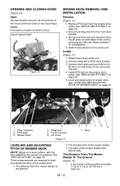
... OF MOWER DECK" on the engine drive pulley. Drag Link 5. Front Trunnion 6. Three measurements are required to level and adjust the pitch of the mower blades. 3. The forward pitch of the mower deck. 1. Disconnect drag link from under unit. 2. Install PTO belt on page 23. 7 16 1. Mower ...Deck 3 4. The Distance From The Mower Blades To The Ground (Figure 12) • In the lowest cutting position should be 1-1/2 in. ± 1/4 in. (3.175 cm ± .635 cm). See ...
... OF MOWER DECK" on the engine drive pulley. Drag Link 5. Front Trunnion 6. Three measurements are required to level and adjust the pitch of the mower blades. 3. The forward pitch of the mower deck. 1. Disconnect drag link from under unit. 2. Install PTO belt on page 23. 7 16 1. Mower ...Deck 3 4. The Distance From The Mower Blades To The Ground (Figure 12) • In the lowest cutting position should be 1-1/2 in. ± 1/4 in. (3.175 cm ± .635 cm). See ...

Owners Manual
Page 23
...or loosen the lock nut on top to secure the link in the desired location. 4. NOTE: This measurement must be taken when the mower blades ends point forward. NOTE: This measurement must be within the tolerances specified. Adjust Trunnions: 1. GB - 23 Repeat step 1 as measured ...on each has been loosened or tightened. 2. Forward Pitch of Mower Blades 3 12 Forward Pitch = 0 in. (0 cm) to level and adjust the pitch of the mower blades from side to side. Mower Deck 2. These measurements are within 1/4 in. (.635 cm) as needed ...
...or loosen the lock nut on top to secure the link in the desired location. 4. NOTE: This measurement must be taken when the mower blades ends point forward. NOTE: This measurement must be within the tolerances specified. Adjust Trunnions: 1. GB - 23 Repeat step 1 as measured ...on each has been loosened or tightened. 2. Forward Pitch of Mower Blades 3 12 Forward Pitch = 0 in. (0 cm) to level and adjust the pitch of the mower blades from side to side. Mower Deck 2. These measurements are within 1/4 in. (.635 cm) as needed ...

Owners Manual
Page 24
... to prevent rotation. 2. Contact your Ariens dealer. Nut Figure 16 SHARPENING MOWER BLADE CAUTION: DO NOT sharpen mower blade while on spindles with mounting hardware. 2. Ariens recommends having mower blades sharpened by sliding mower blade on page 25. GB - 24 Hex Nut Figure 15 REPLACING MOWER BLADE Remove (Figure 16) CAUTION: Mower blades are sharp and can cut...
... to prevent rotation. 2. Contact your Ariens dealer. Nut Figure 16 SHARPENING MOWER BLADE CAUTION: DO NOT sharpen mower blade while on spindles with mounting hardware. 2. Ariens recommends having mower blades sharpened by sliding mower blade on page 25. GB - 24 Hex Nut Figure 15 REPLACING MOWER BLADE Remove (Figure 16) CAUTION: Mower blades are sharp and can cut...

Owners Manual
Page 25
... 3 page 25. See "REPLACING MOWER BLADE" on unit. Cutting Edge Figure 17 SERVICING THE BATTERY NOTE: Unit comes equipped with nut. Tip seat forward. See "TIPPING SEAT FORWARD" on page 22. 2. ...
... 3 page 25. See "REPLACING MOWER BLADE" on unit. Cutting Edge Figure 17 SERVICING THE BATTERY NOTE: Unit comes equipped with nut. Tip seat forward. See "TIPPING SEAT FORWARD" on page 22. 2. ...

Owners Manual
Page 31
...MOVING UNIT MANUALLY" on page 27. 5. Replace hydrostatic belt. Replace PTO belt. Refer to Engine Manual for detailed instructions. 2. Contact your Ariens dealer. 7. Choke engaged. 2. Faulty hydrostatic belt. 3. See "Cleaning Battery and Battery Cables" on page 20. 2. Add engine oil...interlock system. Clean or replace air filter cartridge. Contact your Ariens dealer. 1. Faulty PTO belt. 4. Air filter cartridge plugged. 3. TROUBLESHOOTING PROBLEM Engine will not crank/start. PTO or mower blades do not engage or shut off. Charge battery. Disengage choke...
...MOVING UNIT MANUALLY" on page 27. 5. Replace hydrostatic belt. Replace PTO belt. Refer to Engine Manual for detailed instructions. 2. Contact your Ariens dealer. 7. Choke engaged. 2. Faulty hydrostatic belt. 3. See "Cleaning Battery and Battery Cables" on page 20. 2. Add engine oil...interlock system. Clean or replace air filter cartridge. Contact your Ariens dealer. 1. Faulty PTO belt. 4. Air filter cartridge plugged. 3. TROUBLESHOOTING PROBLEM Engine will not crank/start. PTO or mower blades do not engage or shut off. Charge battery. Disengage choke...

Owners Manual
Page 32
... Raw Laminated Belt Hydraulic Drive 03971900 34-Inch Mower Blade 03797300 34-Inch Mulching Blade 04265400 42-Inch Mower Blade 07200523 42-Inch Deck Belt 03971900 50-Inch Mower Blade 07200524 50-Inch Deck Belt ACCESSORIES See your authorized Ariens dealer to add these optional accessories to keep your Ariens dealer. 2. The parking brake needs adjustment. 2. Hydrostatic transmission...
... Raw Laminated Belt Hydraulic Drive 03971900 34-Inch Mower Blade 03797300 34-Inch Mulching Blade 04265400 42-Inch Mower Blade 07200523 42-Inch Deck Belt 03971900 50-Inch Mower Blade 07200524 50-Inch Deck Belt ACCESSORIES See your authorized Ariens dealer to add these optional accessories to keep your Ariens dealer. 2. The parking brake needs adjustment. 2. Hydrostatic transmission...
Owners Manual
Page 36
..., spark plugs, oil, oil filters, air filters, fuel filters, brake linings, brake arms, brake shoes, skid shoes, scraper blades, shear bolts, mower blades, mower vanes, brushes, headlights, light bulbs, knives, cutters. • Any misuse, alteration, improper assembly, improper adjustment, neglect.... Customer Responsibilities Register the product immediately at owner's expense. • Have the warranty service performed by an authorized Ariens, Gravely or Countax service representative. Items Not Covered by This Warranty • Parts that previous designs were defective. To...
..., spark plugs, oil, oil filters, air filters, fuel filters, brake linings, brake arms, brake shoes, skid shoes, scraper blades, shear bolts, mower blades, mower vanes, brushes, headlights, light bulbs, knives, cutters. • Any misuse, alteration, improper assembly, improper adjustment, neglect.... Customer Responsibilities Register the product immediately at owner's expense. • Have the warranty service performed by an authorized Ariens, Gravely or Countax service representative. Items Not Covered by This Warranty • Parts that previous designs were defective. To...
Parts Catalog
Page 3
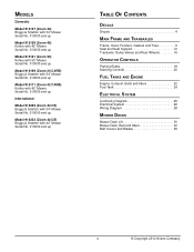
... Serial No. 010000 and up Model 915159 (Zoom 42) Kohler with 42" Mower Serial No. 010000 and up Model 915161 (Zoom 50) Kohler with 50" Mower Serial No. 010000 and up Model 915169 (Zoom 34 CARB) Briggs & Stratton with 34" Mower Serial No. 010000 and up Model 915171 (Zoom 42 CARB) Kohler with 42" Mower Serial... SYSTEM Continuity Diagram 25 Electrical System 26 Wiring Diagram 28 MOWER DECKS Mower Deck Lift 30 Mower Deck, Belt and Idlers 32 Belt Covers and Blades 36 3 © Copyright 2012 Ariens Company
... Serial No. 010000 and up Model 915159 (Zoom 42) Kohler with 42" Mower Serial No. 010000 and up Model 915161 (Zoom 50) Kohler with 50" Mower Serial No. 010000 and up Model 915169 (Zoom 34 CARB) Briggs & Stratton with 34" Mower Serial No. 010000 and up Model 915171 (Zoom 42 CARB) Kohler with 42" Mower Serial... SYSTEM Continuity Diagram 25 Electrical System 26 Wiring Diagram 28 MOWER DECKS Mower Deck Lift 30 Mower Deck, Belt and Idlers 32 Belt Covers and Blades 36 3 © Copyright 2012 Ariens Company
Parts Catalog
Page 36
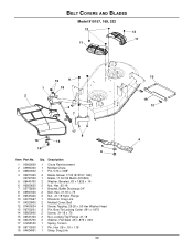
... 17.35 (915157, 169) 1 Blade, 17.34 OS Mulch (915322) 2 Washer, Beveled .63 x 1.625 x .14 2 Nut, Hex .62-18 1 Bracket, Baffle Discharge 34" 2 Bolt, Hex .31-18 x .75 2 Nut, .31-18 Nyloc Flange 1 Wireform, Drag Link 2 Molded Cover, Belt 4 Screw, Tapping .25-20 x .50 Hex Washer Head 2 Pin, Bow Tie Locking... Cotter .091 x 1.875 2 Screw, .31-18 x .75 2 Nut, Locking Top Flange .31-18 2 Washer, Flat Steel .38 x .875 x .083 1 Spring, Torsion 1 Pin, Hair .08 x .18 x 1.18 1 Strap, Drag Link 36 10 19 13 4 BELT COVERS AND BLADES Model 915157, 169, 322...
... 17.35 (915157, 169) 1 Blade, 17.34 OS Mulch (915322) 2 Washer, Beveled .63 x 1.625 x .14 2 Nut, Hex .62-18 1 Bracket, Baffle Discharge 34" 2 Bolt, Hex .31-18 x .75 2 Nut, .31-18 Nyloc Flange 1 Wireform, Drag Link 2 Molded Cover, Belt 4 Screw, Tapping .25-20 x .50 Hex Washer Head 2 Pin, Bow Tie Locking... Cotter .091 x 1.875 2 Screw, .31-18 x .75 2 Nut, Locking Top Flange .31-18 2 Washer, Flat Steel .38 x .875 x .083 1 Spring, Torsion 1 Pin, Hair .08 x .18 x 1.18 1 Strap, Drag Link 36 10 19 13 4 BELT COVERS AND BLADES Model 915157, 169, 322...

Parts Catalog
Page 38
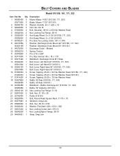
BELT COVERS AND BLADES Model 915159, 161, 171, 323 16 9 20 20 12 10 11 8 17 16 15 20 17 915159, 171, 323 14 5 6 4 7 29 13 21 2 1 21 24 3 20 18 19 23 9 15 17 16 17 14 20 12 22 25 26 20 20 26 27 915161 10 8 28 11 29 7 24 13 19 21 2 18 21 5 1 3 20 6 4 23 38
BELT COVERS AND BLADES Model 915159, 161, 171, 323 16 9 20 20 12 10 11 8 17 16 15 20 17 915159, 171, 323 14 5 6 4 7 29 13 21 2 1 21 24 3 20 18 19 23 9 15 17 16 17 14 20 12 22 25 26 20 20 26 27 915161 10 8 28 11 29 7 24 13 19 21 2 18 21 5 1 3 20 6 4 23 38
Parts Catalog
Page 39
....83" (915159, 171, 323) 03971900 3 Blade, Mower 17.35" (915161) 2 06445700 3 Washer, Bellville .63 x 1.625 x .14 3 06500630 3 Nut, Hex .62-18 4 07056800 3 Bolt, Shoulder .38-16 x 2.50 Hex Washer Head 5 06542000 3 Nut, Locking Top Flange .38-16 6 03905600 4 Anti-Scalp Wheel, 5 x 3 OS (915159, 171, 323) 03905600 3 Anti-Scalp Wheel, 5 x 3 OS (915161) 7 06700201...
....83" (915159, 171, 323) 03971900 3 Blade, Mower 17.35" (915161) 2 06445700 3 Washer, Bellville .63 x 1.625 x .14 3 06500630 3 Nut, Hex .62-18 4 07056800 3 Bolt, Shoulder .38-16 x 2.50 Hex Washer Head 5 06542000 3 Nut, Locking Top Flange .38-16 6 03905600 4 Anti-Scalp Wheel, 5 x 3 OS (915159, 171, 323) 03905600 3 Anti-Scalp Wheel, 5 x 3 OS (915161) 7 06700201...

