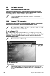
User Guide
Page 2
... express written permission of reproduction and shipment, which you wish to obtain the corresponding source code and your request please provide the name, model number and version, as required under various Free Open Source Software licenses. Product warranty or service ...location where you . No part of their respective companies, and are included in this product. SPECIFICATIONS AND INFORMATION CONTAINED IN THIS MANUAL ARE FURNISHED FOR INFORMATIONAL USE ONLY, AND ARE SUBJECT TO CHANGE AT ANY TIME WITHOUT NOTICE, AND SHOULD NOT BE CONSTRUED AS A COMMITMENT BY ASUS. The source code...
... express written permission of reproduction and shipment, which you wish to obtain the corresponding source code and your request please provide the name, model number and version, as required under various Free Open Source Software licenses. Product warranty or service ...location where you . No part of their respective companies, and are included in this product. SPECIFICATIONS AND INFORMATION CONTAINED IN THIS MANUAL ARE FURNISHED FOR INFORMATIONAL USE ONLY, AND ARE SUBJECT TO CHANGE AT ANY TIME WITHOUT NOTICE, AND SHOULD NOT BE CONSTRUED AS A COMMITMENT BY ASUS. The source code...
User Guide
Page 4
... the BIOS parameters are also provided. How this guide This user guide contains the information you encounter technical problems with the package. • Before using the product, ensure all power cables are unplugged. • Seek professional assistance before the signal cables are connected. If possible, disconnect all power cables from the existing system before you add a device. • Before connecting or removing signal cables from the motherboard...
... the BIOS parameters are also provided. How this guide This user guide contains the information you encounter technical problems with the package. • Before using the product, ensure all power cables are unplugged. • Seek professional assistance before the signal cables are connected. If possible, disconnect all power cables from the existing system before you add a device. • Before connecting or removing signal cables from the motherboard...
User Guide
Page 6
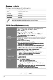
... retailer. Integrated Graphics Processor - Package contents Check your motherboard package for the following items. Motherboard ASUS H81M-R motherboard Cables 2 x Serial ATA 6.0 Gb/s cables Accessories 1 x I/O Shield Application DVD Support DVD Documentation User Guide If any of the above items is subject to 1920 x1200@60Hz - Supports DVI-D with max. Supports D-Sub with max. resolution 1920x1200@60Hz - Supports Intel® Rapid Start Technology* and Intel® Smart Connect Technology** * Due to www.asus.com for Intel® CPU support list. resolution...
... retailer. Integrated Graphics Processor - Package contents Check your motherboard package for the following items. Motherboard ASUS H81M-R motherboard Cables 2 x Serial ATA 6.0 Gb/s cables Accessories 1 x I/O Shield Application DVD Support DVD Documentation User Guide If any of the above items is subject to 1920 x1200@60Hz - Supports DVI-D with max. Supports D-Sub with max. resolution 1920x1200@60Hz - Supports Intel® Rapid Start Technology* and Intel® Smart Connect Technology** * Due to www.asus.com for Intel® CPU support list. resolution...
User Guide
Page 7
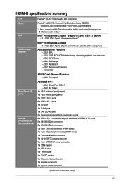
... fan connector (PWM mode) 1 x Front panel audio connector 1 x 24-pin EATX power connector 1 x 4-pin EATX 12V power connector 1 x COM header 1 x LPT header 1 x TPM header 1 x CLRTC header 1 x Chassis Intrusion header 1 x Speaker connector 1 x System panel connector (continued on the next page) vii ASUS Anti-surge Protection - H81M-R specifications summary LAN Audio USB ASUS unique features Back Panel I/O ports Internal I/O connectors/ buttons/switches Realtek® RTL8111GR Gigabit LAN Controller Realtek® ALC887 8-Channel High Definition Audio CODEC - ASUS CrashFree BIOS...
... fan connector (PWM mode) 1 x Front panel audio connector 1 x 24-pin EATX power connector 1 x 4-pin EATX 12V power connector 1 x COM header 1 x LPT header 1 x TPM header 1 x CLRTC header 1 x Chassis Intrusion header 1 x Speaker connector 1 x System panel connector (continued on the next page) vii ASUS Anti-surge Protection - H81M-R specifications summary LAN Audio USB ASUS unique features Back Panel I/O ports Internal I/O connectors/ buttons/switches Realtek® RTL8111GR Gigabit LAN Controller Realtek® ALC887 8-Channel High Definition Audio CODEC - ASUS CrashFree BIOS...

User Guide
Page 9
... handling components, use a grounded wrist strap or touch a safely grounded object or a metal object, such as indicated in the image below. ASUS H81M-R 1-1 Failure to ensure that the ATX power supply is switched off or the power cord is detached from the wall socket before installing or removing the motherboard. The edge with external ports goes to the rear part of the chassis as the power supply case, to avoid...
... handling components, use a grounded wrist strap or touch a safely grounded object or a metal object, such as indicated in the image below. ASUS H81M-R 1-1 Failure to ensure that the ATX power supply is switched off or the power cord is detached from the wall socket before installing or removing the motherboard. The edge with external ports goes to the rear part of the chassis as the power supply case, to avoid...

User Guide
Page 11
... I/O BATTERY Intel® F_PANEL 14 H81 8 AUDIO USB56 USB910 9 SPEAKER SATA3G_2 SATA3G_1 Realtek® 8111GR PCIEX1_1 64Mb BIOS 10 ALC 887 CHASSIS H81M-R 11 AAFP PCIEX16 13 12 1.2.4 Layout contents Connectors/Jumpers/Slots/LED 1. TPM header (20-1 pin TPM) 2. Clear RTC RAM (2-pin CLRTC) 9. Intel® LGA1150 CPU socket 6. CPU and chassis fan connectors (4-pin CPU_FAN, 4-pin CHA_FAN) 3. ATX power connectors (24-pin EATXPWR, 4-pin ATX12V) 4. LPT connector (26-1 pin LPT) 5. Front panel audio connector (10-1 pin AAFP) 14. Serial port connectors (10-1 pin COM...
... I/O BATTERY Intel® F_PANEL 14 H81 8 AUDIO USB56 USB910 9 SPEAKER SATA3G_2 SATA3G_1 Realtek® 8111GR PCIEX1_1 64Mb BIOS 10 ALC 887 CHASSIS H81M-R 11 AAFP PCIEX16 13 12 1.2.4 Layout contents Connectors/Jumpers/Slots/LED 1. TPM header (20-1 pin TPM) 2. Clear RTC RAM (2-pin CLRTC) 9. Intel® LGA1150 CPU socket 6. CPU and chassis fan connectors (4-pin CPU_FAN, 4-pin CHA_FAN) 3. ATX power connectors (24-pin EATXPWR, 4-pin ATX12V) 4. LPT connector (26-1 pin LPT) 5. Front panel audio connector (10-1 pin AAFP) 14. Serial port connectors (10-1 pin COM...
User Guide
Page 15
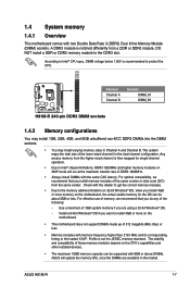
... the DIMM sockets. • You may install varying memory sizes in the market. ASUS H81M-R 1-7 DO NOT install a DDR or DDR2 memory module to Intel® CPU spec, DIMM voltage below 1.65V is then mapped for the dual-channel configuration. The stability and compatibility of these memory modules depend on the motherboard. • This motherboard does not support DIMMs made up of the following: - 1.4 System memory 1.4.1 Overview This motherboard comes with...
... the DIMM sockets. • You may install varying memory sizes in the market. ASUS H81M-R 1-7 DO NOT install a DDR or DDR2 memory module to Intel® CPU spec, DIMM voltage below 1.65V is then mapped for the dual-channel configuration. The stability and compatibility of these memory modules depend on the motherboard. • This motherboard does not support DIMMs made up of the following: - 1.4 System memory 1.4.1 Overview This motherboard comes with...
User Guide
Page 17
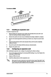
... screw for the card. 2. ASUS H81M-R 1-9 Remove the bracket opposite the slot that you removed earlier. 6. Secure the card to the chassis with it by adjusting the software settings. 1. Install the software drivers for information on the system and change the necessary BIOS settings, if any. Replace the system cover. 1.5.2 Configuring an expansion card After installing the expansion card, configure it and make the necessary hardware settings for later use . Turn on BIOS setup. 2. Otherwise, conflicts will...
... screw for the card. 2. ASUS H81M-R 1-9 Remove the bracket opposite the slot that you removed earlier. 6. Secure the card to the chassis with it by adjusting the software settings. 1. Install the software drivers for information on the system and change the necessary BIOS settings, if any. Replace the system cover. 1.5.2 Configuring an expansion card After installing the expansion card, configure it and make the necessary hardware settings for later use . Turn on BIOS setup. 2. Otherwise, conflicts will...
User Guide
Page 19
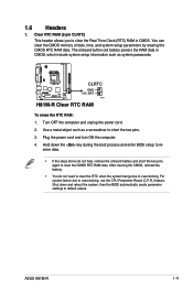
... RAM To erase the RTC RAM: 1. You can clear the CMOS memory of date, time, and system setup parameters by erasing the CMOS RTC RAM data. Use a metal object such as a screwdriver to clear the Real Time Clock (RTC) RAM in CMOS, which include system setup information such as system passwords. For system failure due to overclocking, use the CPU Parameter Recall (C.P.R.) feature. Plug the power cord and turn ON the computer. 4. 1.6 Headers 1. ASUS H81M...
... RAM To erase the RTC RAM: 1. You can clear the CMOS memory of date, time, and system setup parameters by erasing the CMOS RTC RAM data. Use a metal object such as a screwdriver to clear the Real Time Clock (RTC) RAM in CMOS, which include system setup information such as system passwords. For system failure due to overclocking, use the CPU Parameter Recall (C.P.R.) feature. Plug the power cord and turn ON the computer. 4. 1.6 Headers 1. ASUS H81M...

User Guide
Page 21
... port (light blue). This port connects a headphone or a speaker. This port is for USB 2.0/1.1 devices. 10. To configure an 8-channel audio output: Use a chassis with HD audio module in the table. 9. USB 2.0 ports 3 and 4. ASUS H81M-R 1-13 Microphone port (pink). This port connects a microphone. Line Out port (lime). PS/2 keyboard port (purple). In 4-channel, 6-channel, and 8-channel configurations, the function of this port becomes Front Speaker Out. 8. Audio 2.1, 4.1, 5.1 or 7.1-channel configuration Port Light Blue (Rear panel) Lime (Rear panel) Pink (Rear panel...
... port (light blue). This port connects a headphone or a speaker. This port is for USB 2.0/1.1 devices. 10. To configure an 8-channel audio output: Use a chassis with HD audio module in the table. 9. USB 2.0 ports 3 and 4. ASUS H81M-R 1-13 Microphone port (pink). This port connects a microphone. Line Out port (lime). PS/2 keyboard port (purple). In 4-channel, 6-channel, and 8-channel configurations, the function of this port becomes Front Speaker Out. 8. Audio 2.1, 4.1, 5.1 or 7.1-channel configuration Port Light Blue (Rear panel) Lime (Rear panel) Pink (Rear panel...

User Guide
Page 22
... system chassis. 1.7.2 Internal connectors 1. COM CTS DSR DTR RXD RI RTS GND TXD DCD PIN 1 H81M-R H81M-R Serial port connectors The COM module is set the Front Panel Type item in the BIOS setup to a slot opening at the back of the motherboard's high-definition audio capability. • If you want to connect a high-definition front panel audio module to this connector. Serial port connector (10-1 pin COM) This connector is for a chassis-mounted front panel audio I /O module cable to this connector, set to...
... system chassis. 1.7.2 Internal connectors 1. COM CTS DSR DTR RXD RI RTS GND TXD DCD PIN 1 H81M-R H81M-R Serial port connectors The COM module is set the Front Panel Type item in the BIOS setup to a slot opening at the back of the motherboard's high-definition audio capability. • If you want to connect a high-definition front panel audio module to this connector. Serial port connector (10-1 pin COM) This connector is for a chassis-mounted front panel audio I /O module cable to this connector, set to...

User Guide
Page 23
... connector. 3. Only the 4-pin CPU fan support the ASUS Fan Xpert feature. 4. Do not place jumper caps on the motherboard, ensuring that the black wire of each cable matches the ground pin of these connectors, then install the module to the fan connectors on the fan connectors! ASUS H81M-R 1-15 Insufficient air flow inside the system may damage the motherboard components. Doing so will damage the motherboard! CPU and chassis fan connectors (4-pin CPU_FAN, 4-pin CHA_FAN) Connect the fan cables to a slot...
... connector. 3. Only the 4-pin CPU fan support the ASUS Fan Xpert feature. 4. Do not place jumper caps on the motherboard, ensuring that the black wire of each cable matches the ground pin of these connectors, then install the module to the fan connectors on the fan connectors! ASUS H81M-R 1-15 Insufficient air flow inside the system may damage the motherboard components. Doing so will damage the motherboard! CPU and chassis fan connectors (4-pin CPU_FAN, 4-pin CHA_FAN) Connect the fan cables to a slot...
User Guide
Page 28
... an icon to display Support DVD/motherboard information Click to display more items Click an item to install If Autorun is NOT enabled in your ASUS motherboard. Refer to run the Support DVD Place the Support DVD into the optical drive. Double-click the ASSETUP.EXE to your hardware. Click Drivers, Utilities, AHCI Driver, Manual, Contact and Specials tabs to change at www.asus.com for updates. The following screen is enabled in your...
... an icon to display Support DVD/motherboard information Click to display more items Click an item to install If Autorun is NOT enabled in your ASUS motherboard. Refer to run the Support DVD Place the Support DVD into the optical drive. Double-click the ASSETUP.EXE to your hardware. Click Drivers, Utilities, AHCI Driver, Manual, Contact and Specials tabs to change at www.asus.com for updates. The following screen is enabled in your...
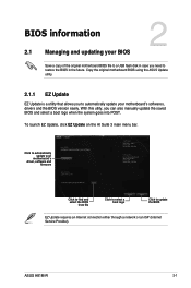
User Guide
Page 29
... 3 main menu bar. Click to automatically update your BIOS 2 Save a copy of the original motherboard BIOS file to a USB flash disk in case you need to restore the BIOS in the future. ASUS H81M-R 2-1 With this utlity, you to update the BIOS EZ Update requires an Internet connection either through a network or an ISP (Internet Service Provider). Copy the original motherboard BIOS using the ASUS Update utility. 2.1.1 EZ Update EZ Update is a utility that allows you can also manually update the...
... 3 main menu bar. Click to automatically update your BIOS 2 Save a copy of the original motherboard BIOS file to a USB flash disk in case you need to restore the BIOS in the future. ASUS H81M-R 2-1 With this utlity, you to update the BIOS EZ Update requires an Internet connection either through a network or an ISP (Internet Service Provider). Copy the original motherboard BIOS using the ASUS Update utility. 2.1.1 EZ Update EZ Update is a utility that allows you can also manually update the...
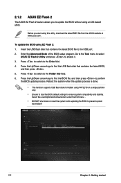
User Guide
Page 30
... load the BIOS default settings to prevent system boot failure! 2-2 Chapter 2: Getting started Select the Load Optimized Defaults item under the Exit menu. . • DO NOT shut down or reset the system while updating the BIOS to ensure system compatibility and stability. Press to switch to enable it. 3. Before you to the USB port. 2. Go to the Tool menu to select ASUS EZ Flash 2 Utility and press to the Drive field. 4. To update the BIOS using...
... load the BIOS default settings to prevent system boot failure! 2-2 Chapter 2: Getting started Select the Load Optimized Defaults item under the Exit menu. . • DO NOT shut down or reset the system while updating the BIOS to ensure system compatibility and stability. Press to switch to enable it. 3. Before you to the USB port. 2. Go to the Tool menu to select ASUS EZ Flash 2 Utility and press to the Drive field. 4. To update the BIOS using...
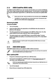
User Guide
Page 31
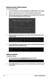
... the removable device to H81MR.CAP. • The BIOS file in your computer has a DVD optical drive. Before updating BIOS • Prepare the motherboard support DVD and a USB flash drive. • Download the latest BIOS file and BIOS Updater from the ASUS website at www.asus.com. Ensure that your USB flash drive is in single partition and in DOS environment. ASUS H81M-R 2-3 You can cause system boot failure! 2.1.4 ASUS BIOS Updater ASUS BIOS Updater allows you to enter BIOS Setup to recover BIOS setting. Turn on your computer screen. The utility...
... the removable device to H81MR.CAP. • The BIOS file in your computer has a DVD optical drive. Before updating BIOS • Prepare the motherboard support DVD and a USB flash drive. • Download the latest BIOS file and BIOS Updater from the ASUS website at www.asus.com. Ensure that your USB flash drive is in single partition and in DOS environment. ASUS H81M-R 2-3 You can cause system boot failure! 2.1.4 ASUS BIOS Updater ASUS BIOS Updater allows you to enter BIOS Setup to recover BIOS setting. Turn on your computer screen. The utility...
User Guide
Page 32
... within five (5) seconds to boot using defaults 4. On the FreeDOS prompt, type d: then press to switch the disk from Drive C (optical drive) to the USB port. 2. Welcome to Drives panel then select D:. 2-4 Chapter 2: Getting started D:/> bupdater /pc /g 2. On the BIOS Updater screen, press to switch from the DVD/CD. On the FreeDOS prompt, type bupdater /pc /g and press . Please select boot device: E1: ASUS DVD-E818A6T (4069MB) USB DISK 2.0 (3824MB) UEFI: (FAT) USB DISK 2.0 (3824MB) Enter Setup and ...
... within five (5) seconds to boot using defaults 4. On the FreeDOS prompt, type d: then press to switch the disk from Drive C (optical drive) to the USB port. 2. Welcome to Drives panel then select D:. 2-4 Chapter 2: Getting started D:/> bupdater /pc /g 2. On the BIOS Updater screen, press to switch from the DVD/CD. On the FreeDOS prompt, type bupdater /pc /g and press . Please select boot device: E1: ASUS DVD-E818A6T (4069MB) USB DISK 2.0 (3824MB) UEFI: (FAT) USB DISK 2.0 (3824MB) Enter Setup and ...
User Guide
Page 33
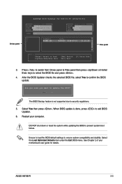
... Drives panel to Files panel then press keys to ensure system compatibility and stability. Select the Load Optimized Defaults item under the Exit BIOS menu. Ensure to load the BIOS default settings to select the BIOS file and press . 4. DO NOT shut down or reset the system while updating the BIOS to exit BIOS Updater. 6. Drives panel ASUSTeK BIOS Updater for details. Yes No The BIOS Backup feature is done, press to prevent system boot failure. Restart your motherboard user guide...
... Drives panel to Files panel then press keys to ensure system compatibility and stability. Select the Load Optimized Defaults item under the Exit BIOS menu. Ensure to load the BIOS default settings to select the BIOS file and press . 4. DO NOT shut down or reset the system while updating the BIOS to exit BIOS Updater. 6. Drives panel ASUSTeK BIOS Updater for details. Yes No The BIOS Backup feature is done, press to prevent system boot failure. Restart your motherboard user guide...
User Guide
Page 34
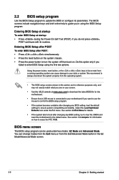
... Mode screen. 2-6 Chapter 2: Getting started You can change modes from the Exit menu or from a running operating system can be used under the Exit menu. Using the power button, reset button, or the ++ keys to erase the RTC RAM. Select the Load Optimized Defaults item under two modes: EZ Mode and Advanced Mode. BIOS menu screen The BIOS setup program can cause damage to the default value. Entering BIOS Setup at startup To enter BIOS Setup at www.asus.com to download the latest BIOS file...
... Mode screen. 2-6 Chapter 2: Getting started You can change modes from the Exit menu or from a running operating system can be used under the Exit menu. Using the power button, reset button, or the ++ keys to erase the RTC RAM. Select the Load Optimized Defaults item under two modes: EZ Mode and Advanced Mode. BIOS menu screen The BIOS setup program can cause damage to the default value. Entering BIOS Setup at startup To enter BIOS Setup at www.asus.com to download the latest BIOS file...

User Guide
Page 35
... the display language of the BIOS setup program Displays the CPU/motherboard temperature, CPU core voltage, DRAM information, CPU/chassis fan speed Exits the BIOS setup program without saving the changes, saves the changes and resets the system, or enters the Advanced Mode Power Saving mode Selects the boot device ASUS Optimal mode Loads optimized default Selects the priority Displays the system properties Advanced mode Normal mode of the basic system information, and allows you to select the display language, system performance mode and boot device priority...
... the display language of the BIOS setup program Displays the CPU/motherboard temperature, CPU core voltage, DRAM information, CPU/chassis fan speed Exits the BIOS setup program without saving the changes, saves the changes and resets the system, or enters the Advanced Mode Power Saving mode Selects the boot device ASUS Optimal mode Loads optimized default Selects the priority Displays the system properties Advanced mode Normal mode of the basic system information, and allows you to select the display language, system performance mode and boot device priority...


