

User Guide
Page 2
..., AutoCAD Development System, AutoCAD LT, AutoCAD Map, Autodesk, Autodesk Animator, Autodesk (logo), Autodesk MapGuide, Autodesk University, Autodesk View, Autodesk WalkThrough, Autodesk World, AutoLISP, AutoShade, AutoSketch, AutoSurf, AutoVision, Biped, bringing information down to ..., and Where Design Connects. Active Delivery™ 2.0 © 1999-2000 Inner Media, Inc. International CorrectSpell™ Spelling Correction System © 1995 by the U. Portions...169; 1989, 1990, 1998 Élan Computer Group, Inc. IN NO EVENT SHALL AUTODESK, INC. REGARDLESS OF THE FORM OF ACTION, ...
..., AutoCAD Development System, AutoCAD LT, AutoCAD Map, Autodesk, Autodesk Animator, Autodesk (logo), Autodesk MapGuide, Autodesk University, Autodesk View, Autodesk WalkThrough, Autodesk World, AutoLISP, AutoShade, AutoSketch, AutoSurf, AutoVision, Biped, bringing information down to ..., and Where Design Connects. Active Delivery™ 2.0 © 1999-2000 Inner Media, Inc. International CorrectSpell™ Spelling Correction System © 1995 by the U. Portions...169; 1989, 1990, 1998 Élan Computer Group, Inc. IN NO EVENT SHALL AUTODESK, INC. REGARDLESS OF THE FORM OF ACTION, ...
User Guide
Page 10
Converting TrueType Fonts 318 Creating Groups 319 Exploding Entities 320 Chapter 26 Making Inquiries 321 Displaying Information About a Specific Entity 322 Displaying Information on the Selection Set 323 Displaying the Coordinates ...
Converting TrueType Fonts 318 Creating Groups 319 Exploding Entities 320 Chapter 26 Making Inquiries 321 Displaying Information About a Specific Entity 322 Displaying Information on the Selection Set 323 Displaying the Coordinates ...
User Guide
Page 23
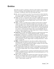
...see the chapter titled "Arcs & Circles," which begins on page 197. Spline curves pass through each control point. s Group-A compound entity consisting of a circle. AutoSketch creates the following entity types: s Arc-An arc is a curved line with every point equally distant from it to...dimension is an entity that moves so the sum of fixed points remains constant. For more information, see the chapter titled "Creating Dimensions," which AutoSketch treats as a water pipe, a wall edge, an electrical connection, or a street. Mathematically, the path of a point that connects two...
...see the chapter titled "Arcs & Circles," which begins on page 197. Spline curves pass through each control point. s Group-A compound entity consisting of a circle. AutoSketch creates the following entity types: s Arc-An arc is a curved line with every point equally distant from it to...dimension is an entity that moves so the sum of fixed points remains constant. For more information, see the chapter titled "Creating Dimensions," which AutoSketch treats as a water pipe, a wall edge, an electrical connection, or a street. Mathematically, the path of a point that connects two...
User Guide
Page 24
... begins on page 137. s Polygon- For more information, see the chapter titled "Polylines, Polygons, & Curves," which begins on , temporarily replace AutoSketch's. s Picture-A raster image is closed polyline that created it becomes a polygon. s Symbol-A symbol is a special entity that can be rotated at...be stored in libraries for use any angle. s Text-A text entity can use in a drawing. s Marker-A marker is a group of connected segments. When you double-click a linked OLE object, Windows opens the source application that can be imported and placed in ...
... begins on page 137. s Polygon- For more information, see the chapter titled "Polylines, Polygons, & Curves," which begins on , temporarily replace AutoSketch's. s Picture-A raster image is closed polyline that created it becomes a polygon. s Symbol-A symbol is a special entity that can be rotated at...be stored in libraries for use any angle. s Text-A text entity can use in a drawing. s Marker-A marker is a group of connected segments. When you double-click a linked OLE object, Windows opens the source application that can be imported and placed in ...
User Guide
Page 27
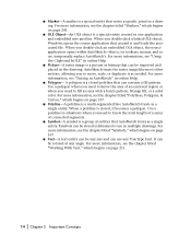
... Layers help you scale the components of the entities in a drawing and their size in relation to actual (world) entities. It allows AutoSketch to accurately depict onscreen how your drawing will look on page 47. For information on how to change . Grid Origin The grid origin is... usually more information, see "Organizing With Layers" in logical groups. By default the grid origin is the ratio between the actual size of a drawing by output size. For more convenient than specifying such ...
... Layers help you scale the components of the entities in a drawing and their size in relation to actual (world) entities. It allows AutoSketch to accurately depict onscreen how your drawing will look on page 47. For information on how to change . Grid Origin The grid origin is... usually more information, see "Organizing With Layers" in logical groups. By default the grid origin is the ratio between the actual size of a drawing by output size. For more convenient than specifying such ...
User Guide
Page 35
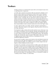
... often contains more buttons than are predefined and cannot be docked alongside one in Microsoft Office 97-compatible products. Each toolset contains a group of the Standard toolbar are divided into toolsets. When the complete toolset appears, drag the pointer to reflect the change the button size... For information on the left edge then dragging it represents. To select a button that perform some of the polyline tools are located in AutoSketch, such as other means, the corresponding button, if it . The All-In-One, Standard, and other toolbars, however, and configure ...
... often contains more buttons than are predefined and cannot be docked alongside one in Microsoft Office 97-compatible products. Each toolset contains a group of the Standard toolbar are divided into toolsets. When the complete toolset appears, drag the pointer to reflect the change the button size... For information on the left edge then dragging it represents. To select a button that perform some of the polyline tools are located in AutoSketch, such as other means, the corresponding button, if it . The All-In-One, Standard, and other toolbars, however, and configure ...
User Guide
Page 100
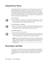
Using Preset Views AutoSketch provides several common views. To view the page in all entities in or out. To view the selection set 1 Select an entity or group of a single window, on the All-In-One toolbar. To view all panes of entities. 2 On the View menu, click Selection, or... view for the selection set , and right-click. The extent view displays all panes of a selection set . For each of these preset views, AutoSketch provides a corresponding command on a specific region. To display the menu, position the pointer inside the selection handles, but not on the All- These ...
Using Preset Views AutoSketch provides several common views. To view the page in all entities in or out. To view the selection set 1 Select an entity or group of a single window, on the All-In-One toolbar. To view all panes of entities. 2 On the View menu, click Selection, or... view for the selection set , and right-click. The extent view displays all panes of a selection set . For each of these preset views, AutoSketch provides a corresponding command on a specific region. To display the menu, position the pointer inside the selection handles, but not on the All- These ...
User Guide
Page 131
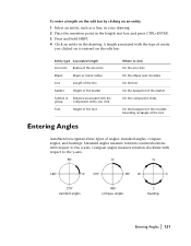
... the line On the basepoint of the marker On the component entity On the basepoint or the invisible bounding rectangle of the text Entering Angles AutoSketch recognizes three types of angles: standard angles, compass angles, and bearings. A length associated with the type of entity you click Text Height of... of the arc/circle Ellipse Major or minor radius Line Length of the line Marker Height of the marker Symbol or Distance associated with the group component entity you clicked on is entered on an entity 1 Select an entity, such as a line, in your drawing. 2 Place the insertion ...
... the line On the basepoint of the marker On the component entity On the basepoint or the invisible bounding rectangle of the text Entering Angles AutoSketch recognizes three types of angles: standard angles, compass angles, and bearings. A length associated with the type of entity you click Text Height of... of the arc/circle Ellipse Major or minor radius Line Length of the line Marker Height of the marker Symbol or Distance associated with the group component entity you clicked on is entered on an entity 1 Select an entity, such as a line, in your drawing. 2 Place the insertion ...
User Guide
Page 177
... the Content Librarian to standardize the look and feel of pre-existing symbols. And, using symbols enhances the performance of entities that AutoSketch treats as a single entity. A symbol is a group of AutoSketch. Symbols 14 Symbols are a way for you can create your drawings eliminates the need to redraw the same thing over and...
... the Content Librarian to standardize the look and feel of pre-existing symbols. And, using symbols enhances the performance of entities that AutoSketch treats as a single entity. A symbol is a group of AutoSketch. Symbols 14 Symbols are a way for you can create your drawings eliminates the need to redraw the same thing over and...
User Guide
Page 178
...you to place symbols in your drawing, you have to place symbols in a drawing by draggingand-dropping a graphic representation of the symbol. Placing a Symbol AutoSketch provides two methods to use the symbol in your drawing. The Content Librarian allows you need only edit one point and Relative snap for the... on page 173. The symbol definition contains all of the information needed to most entity types, symbols are then automatically updated. A symbol is a group of entities that can place a symbol by clicking the drop-down list box and selecting a new symbol library.
...you to place symbols in your drawing, you have to place symbols in a drawing by draggingand-dropping a graphic representation of the symbol. Placing a Symbol AutoSketch provides two methods to use the symbol in your drawing. The Content Librarian allows you need only edit one point and Relative snap for the... on page 173. The symbol definition contains all of the information needed to most entity types, symbols are then automatically updated. A symbol is a group of entities that can place a symbol by clicking the drop-down list box and selecting a new symbol library.
User Guide
Page 184
...libraries. To create a new symbol 1 Select the entities from which begins on page 319. Because they are not assigned a symbol name, groups cannot be saved and recalled from the Basepoint drop-down list box. 5 (optional) Check the Save In Library check box to create a... a method for the symbol in the corresponding text boxes. 9 (optional) Enter a hyperlink in which AutoSketch treats as a single entity, but repeated nesting can deteriorate system performance. Groups have no associated AutoFields and cannot have database values assigned to how many times you create a symbol definition...
...libraries. To create a new symbol 1 Select the entities from which begins on page 319. Because they are not assigned a symbol name, groups cannot be saved and recalled from the Basepoint drop-down list box. 5 (optional) Check the Save In Library check box to create a... a method for the symbol in the corresponding text boxes. 9 (optional) Enter a hyperlink in which AutoSketch treats as a single entity, but repeated nesting can deteriorate system performance. Groups have no associated AutoFields and cannot have database values assigned to how many times you create a symbol definition...
User Guide
Page 191
... nested symbols into their individual component symbols. When the symbol is placed in the Content Librarian makes the symbol current. Managing Symbols in a dining room group symbol, exploding would allow you want to use . 4 Right-click a symbol name. To set . A newly-created symbol always becomes the current symbol. To disable AutoExplode...
... nested symbols into their individual component symbols. When the symbol is placed in the Content Librarian makes the symbol current. Managing Symbols in a dining room group symbol, exploding would allow you want to use . 4 Right-click a symbol name. To set . A newly-created symbol always becomes the current symbol. To disable AutoExplode...

User Guide
Page 196
... overlapping rectangles then draw lines between the corresponding corners, creating the illusion of depth. You can customize how AutoSketch creates 3D Effects in the drawing. AutoSketch allows you to perform 3D effects on an isometric grid. s 3D Parallel Extrusion creates a copy of existing...set that you control how extruded entities are rendered, whether text, groups, or symbols are the basic building blocks of most projects, it is to a transformed copy, creating the illusion of depth. AutoSketch features two ways to simulate three-dimensional drawings: s Parallel and ...
... overlapping rectangles then draw lines between the corresponding corners, creating the illusion of depth. You can customize how AutoSketch creates 3D Effects in the drawing. AutoSketch allows you to perform 3D effects on an isometric grid. s 3D Parallel Extrusion creates a copy of existing...set that you control how extruded entities are rendered, whether text, groups, or symbols are the basic building blocks of most projects, it is to a transformed copy, creating the illusion of depth. AutoSketch features two ways to simulate three-dimensional drawings: s Parallel and ...
User Guide
Page 202
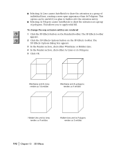
This allows you plan to draw the extrusion as a group of individual lines, creating a more open appearance than As Polygons. s Selecting As Polygons causes AutoSketch to apply solid fill. The 3D Effects toolbar appears. 2 Click the 3D Effects Options button on the Standard toolbar. The 3D Effects Options... or As Polygons. 5 Click OK. 192 | Chapter 15 3D Effects This option can be useful if you to draw the extrusion as a group of polygons. To change the way extrusion entities are rendered 1 Click the 3D Effects button on the 3D Effects toolbar. s Selecting As Lines causes...
This allows you plan to draw the extrusion as a group of individual lines, creating a more open appearance than As Polygons. s Selecting As Polygons causes AutoSketch to apply solid fill. The 3D Effects toolbar appears. 2 Click the 3D Effects Options button on the Standard toolbar. The 3D Effects Options... or As Polygons. 5 Click OK. 192 | Chapter 15 3D Effects This option can be useful if you to draw the extrusion as a group of polygons. To change the way extrusion entities are rendered 1 Click the 3D Effects button on the 3D Effects toolbar. s Selecting As Lines causes...
User Guide
Page 203
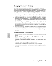
... base entities during an extrusion or perspective operation. s When the AutoExplode Symbols/Groups check box is unchecked, AutoSketch ignores symbols or groups during an extrusion. s The Conversion Quality drop-down list box. 7 Click OK. If this box is converted to a polygon ...text to polylines or polygons during an extrusion. s When the AutoExplode Text check box is checked, AutoSketch treats the original closed entities are displayed, and whether text, symbols and groups are drawn when converted for extrusion. To change the geometry of extrusion entities 1 Click the 3D ...
... base entities during an extrusion or perspective operation. s When the AutoExplode Symbols/Groups check box is unchecked, AutoSketch ignores symbols or groups during an extrusion. s The Conversion Quality drop-down list box. 7 Click OK. If this box is converted to a polygon ...text to polylines or polygons during an extrusion. s When the AutoExplode Text check box is checked, AutoSketch treats the original closed entities are displayed, and whether text, symbols and groups are drawn when converted for extrusion. To change the geometry of extrusion entities 1 Click the 3D ...

User Guide
Page 208
...The pattern of the symbol instance or their pen and pattern properties. Setting Pen Properties Pen properties apply to all entities except symbols and groups, which the entity is displayed or printed. s Width-The width of the entity as makes that property current-meaning that any enclosed ...area-including areas not defined by a single entity. AutoSketch allows you want to copy. s Pen properties (color, style, and width) define the outline of the entity. 198 | Chapter 16 Pen &...
...The pattern of the symbol instance or their pen and pattern properties. Setting Pen Properties Pen properties apply to all entities except symbols and groups, which the entity is displayed or printed. s Width-The width of the entity as makes that property current-meaning that any enclosed ...area-including areas not defined by a single entity. AutoSketch allows you want to copy. s Pen properties (color, style, and width) define the outline of the entity. 198 | Chapter 16 Pen &...
User Guide
Page 210
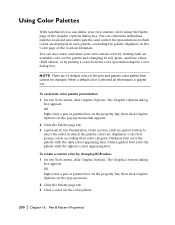
... using the Color dialog box. When a default color is selected all information is grayed out. Color Sort groups colors according their color category. The Graphic Options dialog box appears. Using Color Palettes With AutoSketch you can customize individual palettes, load and save entire palettes, and control the presentation in which the palette...
... using the Color dialog box. When a default color is selected all information is grayed out. Color Sort groups colors according their color category. The Graphic Options dialog box appears. Using Color Palettes With AutoSketch you can customize individual palettes, load and save entire palettes, and control the presentation in which the palette...
User Guide
Page 259
This group consists of the current selection set. With each change, the handles are selected can be acted upon. To delete an entity, for the entire selection ... entities in the drawing. This chapter describes all selected entities. Any action you must select it becomes part of the techniques for selecting entities in AutoSketch. Selecting & Deleting Entities 20 In general, only entities that are adjusted to reflect the extent of highlighted entities surrounded by handles.
This group consists of the current selection set. With each change, the handles are selected can be acted upon. To delete an entity, for the entire selection ... entities in the drawing. This chapter describes all selected entities. Any action you must select it becomes part of the techniques for selecting entities in AutoSketch. Selecting & Deleting Entities 20 In general, only entities that are adjusted to reflect the extent of highlighted entities surrounded by handles.
User Guide
Page 262
... is a word that identifies a specific condition. To select all symbols that represent equipment purchased from the selection set based on their properties. This statement describes a group of entities using qualifiers and operators. To specify the entities you want to reposition the drawing on the page, align the entire drawing to form...
... is a word that identifies a specific condition. To select all symbols that represent equipment purchased from the selection set based on their properties. This statement describes a group of entities using qualifiers and operators. To specify the entities you want to reposition the drawing on the page, align the entire drawing to form...
User Guide
Page 266
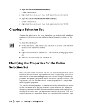
... or graphic properties. When you are done with each entity type. 256 | Chapter 20 Selecting & Deleting Entities Clearing a Selection Set Clearing the selection set is a group of controls appears on the edit bar and property bar to make accidental changes to the entity's geometric and graphic properties. Modifying the Properties for...
... or graphic properties. When you are done with each entity type. 256 | Chapter 20 Selecting & Deleting Entities Clearing a Selection Set Clearing the selection set is a group of controls appears on the edit bar and property bar to make accidental changes to the entity's geometric and graphic properties. Modifying the Properties for...