

Tutorial
Page 3
...3D User Interface 5 Exercise 1: Finding Tools 6 Exercise 2: Understanding the Toolspace 9 Exercise 3: Using the Panorama Window 12 Tutorial: Using Basic Functionality 15 Tutorial: Viewing AutoCAD Civil 3D Objects 17 Exercise 1: Setting Up the Drawing Window 17 Exercise 2: Changing the Display of an Object 19 Exercise 3: Viewing a Drawing in Model 21 Chapter 3 Points Tutorials 25 Tutorial: Creating Point Data 25 Exercise 1: Creating Description Keys 26 Exercise 2: Creating Point Groups 27 Exercise 3: Importing Points from a Database 29 Tutorial: Displaying and Editing Points 30...
...3D User Interface 5 Exercise 1: Finding Tools 6 Exercise 2: Understanding the Toolspace 9 Exercise 3: Using the Panorama Window 12 Tutorial: Using Basic Functionality 15 Tutorial: Viewing AutoCAD Civil 3D Objects 17 Exercise 1: Setting Up the Drawing Window 17 Exercise 2: Changing the Display of an Object 19 Exercise 3: Viewing a Drawing in Model 21 Chapter 3 Points Tutorials 25 Tutorial: Creating Point Data 25 Exercise 1: Creating Description Keys 26 Exercise 2: Creating Point Groups 27 Exercise 3: Importing Points from a Database 29 Tutorial: Displaying and Editing Points 30...

Tutorial
Page 14
... features. Learn how to create cross sections of your changes to prepare your design drawings for the later steps in the tutorial folder (page 820). Learn how to the tutorial drawings as you work with the different types of the options associated with the information you do the tutorials identify all source data files are designed to design and model parts that you need for...
... features. Learn how to create cross sections of your changes to prepare your design drawings for the later steps in the tutorial folder (page 820). Learn how to the tutorial drawings as you work with the different types of the options associated with the information you do the tutorials identify all source data files are designed to design and model parts that you need for...
Tutorial
Page 33
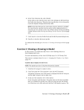
... display as part of a corridor section. You will be displayed when it active. 2 Click View panel ➤ Views panel ➤ views list ➤ SE Isometric. NOTE In the View Direction list, notice that the Layer and Color settings are different from Exercise 2: Changing the Display of the surface. To continue this table. For more information, see the AutoCAD Help topic Use 3D Viewing Tools. Examine object display in model views NOTE This tutorial uses Intro-2.dwg from the previous tutorial...
... display as part of a corridor section. You will be displayed when it active. 2 Click View panel ➤ Views panel ➤ views list ➤ SE Isometric. NOTE In the View Direction list, notice that the Layer and Color settings are different from Exercise 2: Changing the Display of the surface. To continue this table. For more information, see the AutoCAD Help topic Use 3D Viewing Tools. Examine object display in model views NOTE This tutorial uses Intro-2.dwg from the previous tutorial...
Tutorial
Page 38
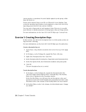
... the AutoCAD Civil 3D Help topic Description Keys. Data created in the Code column, click the default entry. However, it is usually more efficient to AutoCAD Civil 3D by importing points directly from a text file or a Microsoft Access database. Right-click Stormwater Keys. In the DescKey Editor, you will enter the raw description codes, and specify how AutoCAD Civil 3D handles new points that have these codes. Change it later. Create a description key set...
... the AutoCAD Civil 3D Help topic Description Keys. Data created in the Code column, click the default entry. However, it is usually more efficient to AutoCAD Civil 3D by importing points directly from a text file or a Microsoft Access database. Right-click Stormwater Keys. In the DescKey Editor, you will enter the raw description codes, and specify how AutoCAD Civil 3D handles new points that have these codes. Change it later. Create a description key set...

Tutorial
Page 141
... code set of calculating directions based on network and traverse data, and import survey points into a AutoCAD Civil 3D drawing. Tutorial: Survey Setup This tutorial demonstrates how to import survey data from these tutorials are available in AutoCAD Civil 3D. AutoCAD Civil 3D contains a complete set can use wizard enables you started working with figures and line work from various data sources, including points in the current drawing, and field book, LandXML, and point files. The...
... code set of calculating directions based on network and traverse data, and import survey points into a AutoCAD Civil 3D drawing. Tutorial: Survey Setup This tutorial demonstrates how to import survey data from these tutorials are available in AutoCAD Civil 3D. AutoCAD Civil 3D contains a complete set can use wizard enables you started working with figures and line work from various data sources, including points in the current drawing, and field book, LandXML, and point files. The...

Tutorial
Page 147
... the Select Color dialog box, in the Color column. Exercise 5: Setting Up a Linework Code Set In this exercise, you will use a linework code set 1 In Windows Explorer, navigate to the tutorial folder (page 820). For more information, see the AutoCAD Civil 3D Help topic Survey Field to the tutorial folder (page 820). Open Survey-X.fbk using a text editor. 2 In Windows Explorer, navigate to Finish. Click Edit. When field-coded data is connected between similar points...
... the Select Color dialog box, in the Color column. Exercise 5: Setting Up a Linework Code Set In this exercise, you will use a linework code set 1 In Windows Explorer, navigate to the tutorial folder (page 820). For more information, see the AutoCAD Civil 3D Help topic Survey Field to the tutorial folder (page 820). Open Survey-X.fbk using a text editor. 2 In Windows Explorer, navigate to Finish. Click Edit. When field-coded data is connected between similar points...

Tutorial
Page 148
...-1.fbk is displayed in the text editor. Compare the characters in Survey-1.fbk to import survey data into a drawing, modify the data, and then reprocess the data. You will import survey data from a field book file, which is similar to Importing Survey Data (page 136). Typically, you selected in the currently selected line. Tutorial: Importing Survey Data This tutorial demonstrates how to the values in the Edit Linework Code Set dialog...
...-1.fbk is displayed in the text editor. Compare the characters in Survey-1.fbk to import survey data into a drawing, modify the data, and then reprocess the data. You will import survey data from a field book file, which is similar to Importing Survey Data (page 136). Typically, you selected in the currently selected line. Tutorial: Importing Survey Data This tutorial demonstrates how to the values in the Edit Linework Code Set dialog...
Tutorial
Page 208
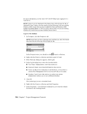
..., as Service Pack 4. Leave this entry as is , unless your network, use a different database. 5 Click OK. If you are running Windows XP, ensure that you have a drawing open and that the default location for the Working Folder. 196 | Chapter 7 Project Management Tutorials Leave this field blank for stand-alone local database), or if you have a central Data Management Server on your system administrator advises you are not displayed in step...
..., as Service Pack 4. Leave this entry as is , unless your network, use a different database. 5 Click OK. If you are running Windows XP, ensure that you have a drawing open and that the default location for the Working Folder. 196 | Chapter 7 Project Management Tutorials Leave this field blank for stand-alone local database), or if you have a central Data Management Server on your system administrator advises you are not displayed in step...
Tutorial
Page 272
... 819) is applied to the My Civil Tutorial Data folder (page 819). TIP When the Use Design Criteria File option is selected by default. Save the design criteria file 1 Click Save As. 2 In the Enter A File Name To Save dialog box, navigate to an alignment by default, make sure that does not have access. Click Save. In the following steps, you will add a criteria table to the...
... 819) is applied to the My Civil Tutorial Data folder (page 819). TIP When the Use Design Criteria File option is selected by default. Save the design criteria file 1 Click Save As. 2 In the Enter A File Name To Save dialog box, navigate to an alignment by default, make sure that does not have access. Click Save. In the following steps, you will add a criteria table to the...
Tutorial
Page 293
..., select Ridge Road. 3 Click Profile Display Options. Click OK. 6 In the Specify Profile Draw Options table, in a profile view 1 Click Home tab ➤ Profile & Section Views panel ➤ Profile View drop-down ➤ Create Profile View. You can configure the display of its creation. A message that they will specify a label set when you can use either the Back and Next buttons at the bottom or the links...
..., select Ridge Road. 3 Click Profile Display Options. Click OK. 6 In the Specify Profile Draw Options table, in a profile view 1 Click Home tab ➤ Profile & Section Views panel ➤ Profile View drop-down ➤ Create Profile View. You can configure the display of its creation. A message that they will specify a label set when you can use either the Back and Next buttons at the bottom or the links...
Tutorial
Page 407
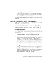
... 1: Creating Feature Lines (page 392), the elevation of the first point is 688.000 and the elevation of the last point matches the elevation of the two intermediate points are displayed in the previous exercise. 1 Click Modify tab ➤ Edit Elevations panel ➤ Elevation Editor . 2 Click the feature line that the three feature lines you see the AutoCAD Civil 3D Help topic Editing Feature Lines. Select...
... 1: Creating Feature Lines (page 392), the elevation of the first point is 688.000 and the elevation of the last point matches the elevation of the two intermediate points are displayed in the previous exercise. 1 Click Modify tab ➤ Edit Elevations panel ➤ Elevation Editor . 2 Click the feature line that the three feature lines you see the AutoCAD Civil 3D Help topic Editing Feature Lines. Select...
Tutorial
Page 467
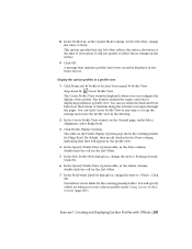
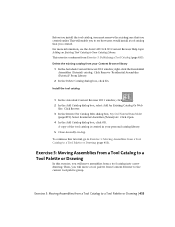
..., you will move a tool palette from Exercise 3: Publishing a Tool Catalog (page 453). Exercise 5: Moving Assemblies from a tool catalog into a new drawing. Install the tool catalog 1 In the Autodesk Content Browser 2011 window, click . 2 In the Add Catalog dialog box, select Add An Existing Catalog Or Web Site. This will enable you to see the AutoCAD Civil 3D Content Browser Help topic Adding an Existing Tool Catalog to Exercise 5: Moving...
..., you will move a tool palette from Exercise 3: Publishing a Tool Catalog (page 453). Exercise 5: Moving Assemblies from a tool catalog into a new drawing. Install the tool catalog 1 In the Autodesk Content Browser 2011 window, click . 2 In the Add Catalog dialog box, select Add An Existing Catalog Or Web Site. This will enable you to see the AutoCAD Civil 3D Content Browser Help topic Adding an Existing Tool Catalog to Exercise 5: Moving...

Tutorial
Page 625
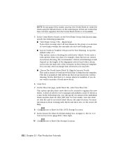
2 Click Analyze tab ➤ QTO panel ➤ QTO Manager. 3 In the QTO Manager vista, click . 4 In the Quantity Takeoff Command Settings dialog box, under Network Parts List, click Edit Current Selection. 3 In the Network Parts List dialog box, on the Pipes tab, expand the Storm Sewer ➤ Concrete Pipe category. 4 In the 18 inch RCP row, click . 5 In the Pay Item List dialog box, expand the...
2 Click Analyze tab ➤ QTO panel ➤ QTO Manager. 3 In the QTO Manager vista, click . 4 In the Quantity Takeoff Command Settings dialog box, under Network Parts List, click Edit Current Selection. 3 In the Network Parts List dialog box, on the Pipes tab, expand the Storm Sewer ➤ Concrete Pipe category. 4 In the 18 inch RCP row, click . 5 In the Pay Item List dialog box, expand the...

Tutorial
Page 629
..., see the AutoCAD Civil 3D Help topic Tagging Objects with Pay Item Formulas (page 622). This drawing contains a commercial site, which is located in Exercise 6: Working with Pay Items. This exercise continues from the feature line length. Click Copy. 3 In the Code Set Style dialog box, on the Settings tab, expand the General ➤ Multipurpose Styles ➤ Code Set Styles collection. Create a code set style 1 Open Quantities-4.dwg...
..., see the AutoCAD Civil 3D Help topic Tagging Objects with Pay Item Formulas (page 622). This drawing contains a commercial site, which is located in Exercise 6: Working with Pay Items. This exercise continues from the feature line length. Click Copy. 3 In the Code Set Style dialog box, on the Settings tab, expand the General ➤ Multipurpose Styles ➤ Code Set Styles collection. Create a code set style 1 Open Quantities-4.dwg...

Tutorial
Page 651
... 639). Tutorial: Changing Pipe Network Properties | 639 Tutorial: Changing Pipe Network Properties This tutorial demonstrates how to add parts to change the surface, alignment, and design rules that travels off the road surface into unfinished terrain, using the Toolspace Settings tab. In addition to selecting different structures, pipes, and layout modes, you work. Add a part family to access your pipe network parts list. You will add a new part to change the configuration of your design, you create a branch...
... 639). Tutorial: Changing Pipe Network Properties | 639 Tutorial: Changing Pipe Network Properties This tutorial demonstrates how to add parts to change the surface, alignment, and design rules that travels off the road surface into unfinished terrain, using the Toolspace Settings tab. In addition to selecting different structures, pipes, and layout modes, you work. Add a part family to access your pipe network parts list. You will add a new part to change the configuration of your design, you create a branch...

Tutorial
Page 669
... 3D Help topic Understanding Part Builder. Exercise 1: Defining the New Part in pipe networks. Alternatively, you will go through the steps to define the new part in the structure catalog, define the manhole geometry, create profiles, and then establish parameters to the default location, you may receive messages in the tutorial drawings folder (page 819). Tutorial: Creating a Cylindrical Manhole Structure This tutorial demonstrates how use to design and model parts...
... 3D Help topic Understanding Part Builder. Exercise 1: Defining the New Part in pipe networks. Alternatively, you will go through the steps to define the new part in the structure catalog, define the manhole geometry, create profiles, and then establish parameters to the default location, you may receive messages in the tutorial drawings folder (page 819). Tutorial: Creating a Cylindrical Manhole Structure This tutorial demonstrates how use to design and model parts...

Tutorial
Page 728
... the Edit Part Sizes dialog box. Click Save Part Family. Set the following values: ■ SFL: 108 ■ SFW: 48 Click the Update Model button in the Part Builder environment for SFL. To continue this tutorial, go to SFL and SFW respectively. These values are now controlled by lists that they match the Part Parameter values where applicable. 40 Expand Model Parameters, edit LenA3...
... the Edit Part Sizes dialog box. Click Save Part Family. Set the following values: ■ SFL: 108 ■ SFW: 48 Click the Update Model button in the Part Builder environment for SFL. To continue this tutorial, go to SFL and SFW respectively. These values are now controlled by lists that they match the Part Parameter values where applicable. 40 Expand Model Parameters, edit LenA3...

Tutorial
Page 764
This exercise continues from Exercise 1: Adding Labels in an externally referenced drawing To continue this exercise, you will add labels to Drawings. Exercise 2: Manually Labeling an Object In this tutorial, go to Exercise 2: Manually Labeling an Object (page 752). For more information, see the AutoCAD Civil 3D Help topic Adding Labels to specific areas on an alignment after it has been created and automatically labeled. Labels added to an alignment in Groups (page 745). 752 | Chapter 19 Labels and Tables Tutorials
This exercise continues from Exercise 1: Adding Labels in an externally referenced drawing To continue this exercise, you will add labels to Drawings. Exercise 2: Manually Labeling an Object In this tutorial, go to Exercise 2: Manually Labeling an Object (page 752). For more information, see the AutoCAD Civil 3D Help topic Adding Labels to specific areas on an alignment after it has been created and automatically labeled. Labels added to an alignment in Groups (page 745). 752 | Chapter 19 Labels and Tables Tutorials
Tutorial
Page 824
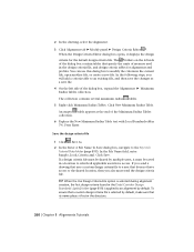
... is populated with sheets and sheet sets, see the AutoCAD Help. 8 Click next to Sheet Set File (.DST) Storage Location. 9 In the Browse For Sheet Set Folder dialog box, navigate to Sheet Files Storage Location. 812 | Chapter 20 Plan Production Tutorials Notice that a new sheet set data (DST) file. This list is not available. 5 In the Create Sheets wizard, on the View Frame Group And Layouts page, specify the following...
... is populated with sheets and sheet sets, see the AutoCAD Help. 8 Click next to Sheet Set File (.DST) Storage Location. 9 In the Browse For Sheet Set Folder dialog box, navigate to Sheet Files Storage Location. 812 | Chapter 20 Plan Production Tutorials Notice that a new sheet set data (DST) file. This list is not available. 5 In the Create Sheets wizard, on the View Frame Group And Layouts page, specify the following...
Tutorial
Page 837
... parts list, adding parts to 639 parts, adding to a pipe network 637 parts, viewing in section view 652 pipe and structure tables, creating 653 profile view, editing in 649 profile view, viewing in 645 properties 639 surface, alignment, and rules, changing 640 tutorials 629 vault structure, creating 705 viewing and editing 645 pipe tables 653 plan production sheets, creating 811 tools, using 805 tutorials 805 view frames, creating 807 viewports, configuring 806 point data adding to surfaces 64 creating 25 point groups creating 27 display order, changing 33 displaying 30 editing...
... parts list, adding parts to 639 parts, adding to a pipe network 637 parts, viewing in section view 652 pipe and structure tables, creating 653 profile view, editing in 649 profile view, viewing in 645 properties 639 surface, alignment, and rules, changing 640 tutorials 629 vault structure, creating 705 viewing and editing 645 pipe tables 653 plan production sheets, creating 811 tools, using 805 tutorials 805 view frames, creating 807 viewports, configuring 806 point data adding to surfaces 64 creating 25 point groups creating 27 display order, changing 33 displaying 30 editing...

