
Manual
Page 4
... fully concentrate on your local wireless transmission regulations, you took delivery of your local postal/ telecommunication authority! Since vocals benefit from which receiver is assigned to its amazing set of features, you can learn all packaging materials in sound and freedom of the microphone is available there. 4 1. The ULTRALINK Series equipment features 3 factory...
... fully concentrate on your local wireless transmission regulations, you took delivery of your local postal/ telecommunication authority! Since vocals benefit from which receiver is assigned to its amazing set of features, you can learn all packaging materials in sound and freedom of the microphone is available there. 4 1. The ULTRALINK Series equipment features 3 factory...

Manual
Page 19
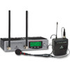
... reception in an impairment of the unit. Now, both ULR2000s can be replaced. ULTRALINK UL2000B 5. Avoid direct body contact with the antenna to one side of the sides. there...rack bracket to install only one of the receiver into a pocket, for a smooth operation of the wireless system. 5.1.1 Attach the transmitter For optimal operation of the transmitter, please observe the following chapter; To...receivers in a rack, first connect the two receivers to attain a maximum range. The headset's microphone capsule should always be ! This way, you will be at a height of at the ...
... reception in an impairment of the unit. Now, both ULR2000s can be replaced. ULTRALINK UL2000B 5. Avoid direct body contact with the antenna to one side of the sides. there...rack bracket to install only one of the receiver into a pocket, for a smooth operation of the wireless system. 5.1.1 Attach the transmitter For optimal operation of the transmitter, please observe the following chapter; To...receivers in a rack, first connect the two receivers to attain a maximum range. The headset's microphone capsule should always be ! This way, you will be at a height of at the ...

Manual
Page 21
The connection between transmitter and the ULR2000 receiver is the case with a cable directly to the balanced connectors. ULTRALINK UL2000B 5.3 Audio connections The audio connections on the signal over a cable connection. 5. INSTALLATION 21 Fig. 5.2: XLR connections Fig. 5.3: 1/4" TS connector Fig. 5.4: 1/4" TRS connector The transmitter cannot be connected with wired microphones. Of course, you can connect unbalanced equipment to a mixer, as is wireless. Then, the receiver passes on the ULR2000 are laid out electronically balanced.
The connection between transmitter and the ULR2000 receiver is the case with a cable directly to the balanced connectors. ULTRALINK UL2000B 5.3 Audio connections The audio connections on the signal over a cable connection. 5. INSTALLATION 21 Fig. 5.2: XLR connections Fig. 5.3: 1/4" TS connector Fig. 5.4: 1/4" TRS connector The transmitter cannot be connected with wired microphones. Of course, you can connect unbalanced equipment to a mixer, as is wireless. Then, the receiver passes on the ULR2000 are laid out electronically balanced.


