
Bios Setup
Page 4
... 'Day' automatically changes when you enter AMI BIOS Setup Utility, the Main Menu will be excluded.. Use [+] or [-] to select a field. System Memory Shows system memory size, VGA shard memory will appear on the screen providing an overview of floppy disk drive installed in / None 3 Floppy A Select the type of the basic system... Performance Exit System Overview AMI BIOS Version :01.01.01 Build Date:01/01/10 Use [ENTER], [TAB] or [SHIFT-TAB] to configure system Time. G41U3G BIOS Manual 1 Main Menu Once you set the date.
... 'Day' automatically changes when you enter AMI BIOS Setup Utility, the Main Menu will be excluded.. Use [+] or [-] to select a field. System Memory Shows system memory size, VGA shard memory will appear on the screen providing an overview of floppy disk drive installed in / None 3 Floppy A Select the type of the basic system... Performance Exit System Overview AMI BIOS Version :01.01.01 Build Date:01/01/10 Use [ENTER], [TAB] or [SHIFT-TAB] to configure system Time. G41U3G BIOS Manual 1 Main Menu Once you set the date.

Bios Setup
Page 9
... hardw are prefetch er that automatically analy zes its capabilities. Options: Disabled (Default) / Enabled 8 G41U3G BIOS Manual Intel(R) SpeedStep(tm) Tech T his reduces the latency associated with memory reads. Befo re it can provide the operating system. T his item allows you to enable SpeedStep technology... has a h ardw are likely to identify the processor and its requirements and prefetches dat a and instructions from the memory into some Intel processors that automatically fetches an extra 64-byte cache line whenev er the processo r requests for better power saving.
... hardw are prefetch er that automatically analy zes its capabilities. Options: Disabled (Default) / Enabled 8 G41U3G BIOS Manual Intel(R) SpeedStep(tm) Tech T his reduces the latency associated with memory reads. Befo re it can provide the operating system. T his item allows you to enable SpeedStep technology... has a h ardw are likely to identify the processor and its requirements and prefetches dat a and instructions from the memory into some Intel processors that automatically fetches an extra 64-byte cache line whenev er the processo r requests for better power saving.
Bios Setup
Page 12
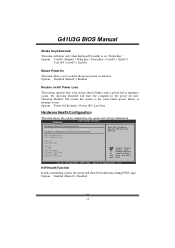
...the system temperature, fan speed, and voltage information. CPU Temperature SYS Temperature CPU Fan System1 Fan +12.0V +5.00V CPU Voltage Chipset Voltage FSB Voltage Memory Voltage Select Screen Select Item +- Change Option F1 General Help F10 Save and Exit ESC Exit vxx.xx (C)Copyright 1985-200x, American Megatrends, Inc....AC Power Loss T his setting specifies how your system should behave after a power fail or interrupts occurs. Options: Disabled (Default) / Enabled Restore on function. G41U3G BIOS Manual Stroke Keys Selected T his item will show PC health status during POST stage.
...the system temperature, fan speed, and voltage information. CPU Temperature SYS Temperature CPU Fan System1 Fan +12.0V +5.00V CPU Voltage Chipset Voltage FSB Voltage Memory Voltage Select Screen Select Item +- Change Option F1 General Help F10 Save and Exit ESC Exit vxx.xx (C)Copyright 1985-200x, American Megatrends, Inc....AC Power Loss T his setting specifies how your system should behave after a power fail or interrupts occurs. Options: Disabled (Default) / Enabled Restore on function. G41U3G BIOS Manual Stroke Keys Selected T his item will show PC health status during POST stage.

Bios Setup
Page 16
... S3/S4 function. Options: FED00000h (Default) / FED01000h / FED02000h / FED03000h EUP Control (Optional) W hen EUP is enabled, the system will meet EUP requirement. G41U3G BIOS Manual USB Dev ice Wakeup from S3/S4 T his item allows you to control the wake on motherboard to enable if applicabl e. Options: Disabled... (Default) / Enabled Resume On PME# When you can set the memory address of HPET . Set the Wake on LAN (WOL) jumper on ring function. For this function to work, you may need a LAN add-...
... S3/S4 function. Options: FED00000h (Default) / FED01000h / FED02000h / FED03000h EUP Control (Optional) W hen EUP is enabled, the system will meet EUP requirement. G41U3G BIOS Manual USB Dev ice Wakeup from S3/S4 T his item allows you to control the wake on motherboard to enable if applicabl e. Options: Disabled... (Default) / Enabled Resume On PME# When you can set the memory address of HPET . Set the Wake on LAN (WOL) jumper on ring function. For this function to work, you may need a LAN add-...

Bios Setup
Page 20
...be used by Legacy ISA devices. DMA Channel 0 DMA Channel 1 DMA Channel 3 DMA Channel 5 DMA Channel 6 DMA Channel 7 Reserved Memory Size [Available] [Available] [Available] [Available] [Available] [Available] [Disabled] Select Screen Select Item +- This item allows such snooping to perform DMA (Direct... Memory Access) trans fers. Options: Disabled (Default) / Enabled PCI IDE BusMaster T his item allows BIOS to choose a IRQ to assign for the PCI VGA card. G41U3G BIOS Manual PCI Latency Timer T his item controls how long ...
...be used by Legacy ISA devices. DMA Channel 0 DMA Channel 1 DMA Channel 3 DMA Channel 5 DMA Channel 6 DMA Channel 7 Reserved Memory Size [Available] [Available] [Available] [Available] [Available] [Available] [Disabled] Select Screen Select Item +- This item allows such snooping to perform DMA (Direct... Memory Access) trans fers. Options: Disabled (Default) / Enabled PCI IDE BusMaster T his item allows BIOS to choose a IRQ to assign for the PCI VGA card. G41U3G BIOS Manual PCI Latency Timer T his item controls how long ...

Bios Setup
Page 21
... State Power-Management[Disabled] Enable/Disable PCI Express L0s and L1 link power states. Options: Available (Default) / Reserved Reserved Memory Size T his item allows BIOS to assign automatically. Active State Power-Management T his function is going to reserve cert ain... memory size for the PCI Express devices b efore the operating system boots. G41U3G BIOS Manual IRQ3/4/5/7/9/10/11/14/15 T hese items will allow you to assign each system interrupt a ...
... State Power-Management[Disabled] Enable/Disable PCI Express L0s and L1 link power states. Options: Available (Default) / Reserved Reserved Memory Size T his item allows BIOS to assign automatically. Active State Power-Management T his function is going to reserve cert ain... memory size for the PCI Express devices b efore the operating system boots. G41U3G BIOS Manual IRQ3/4/5/7/9/10/11/14/15 T hese items will allow you to assign each system interrupt a ...

Bios Setup
Page 25
... PCI bus. T his submenu allows you to configure the speci fic features of that setting inappropriate values in below sections may cause system to malfunction. G41U3G BIOS Manual 5 Chipset Menu T his chipset manage bus speeds and access to system...
... PCI bus. T his submenu allows you to configure the speci fic features of that setting inappropriate values in below sections may cause system to malfunction. G41U3G BIOS Manual 5 Chipset Menu T his chipset manage bus speeds and access to system...

Bios Setup
Page 26
... OS supports this area is decided, this area of system memory for the memory requirements. When the memory size is reserved it cannot be cached. G41U3G BIOS Manual North Bridge Configuration BIOS SETUP UTILITY Chipset North Bridge Chipset Configuration Memory Remap Feature PCI MMIO Allocation: Memory Hole [Enabled] [Disabled] Initiate Graphic Adapter [PEG/PCI] IGD Graphics...
... OS supports this area is decided, this area of system memory for the memory requirements. When the memory size is reserved it cannot be cached. G41U3G BIOS Manual North Bridge Configuration BIOS SETUP UTILITY Chipset North Bridge Chipset Configuration Memory Remap Feature PCI MMIO Allocation: Memory Hole [Enabled] [Disabled] Initiate Graphic Adapter [PEG/PCI] IGD Graphics...

Bios Setup
Page 27
... to enable both Onboard and external PCIE Graphic card display concurrently. T his BIOS feature is an enhancement of the unified memory architecture (UMA) concept. Options: 256MB (Default) / 128MB / Maximum DVMT 26 G41U3G BIOS Manual Onboard VGA T his item allows you to select the DVMT mode. C hange Option F1 G eneral Help F1 0 S ave...
... to enable both Onboard and external PCIE Graphic card display concurrently. T his BIOS feature is an enhancement of the unified memory architecture (UMA) concept. Options: 256MB (Default) / 128MB / Maximum DVMT 26 G41U3G BIOS Manual Onboard VGA T his item allows you to select the DVMT mode. C hange Option F1 G eneral Help F1 0 S ave...

Bios Setup
Page 30
... Control by superio PSI Control CPU Frequency Setting PCIE Clock By PCIE Frequency Setting [Enabled] [333] [Auto] [100] CPU Voltage FSB Voltage Memory Voltage Chipset Voltage DRAM Frequency Configure DRAM Timing by SPD [Default] [Default] [Default] [Default] [Auto] [Enabled] Select Screen Select Item ... Advanced BIOS SETUP UTILITY PCIPnP Boot Chipset Performance Exit Advance Performance Settings WARNING:Please Clear CMOS if system no display after overclocking. G41U3G BIOS Manual 6 Performance Menu T his submenu allows you to change voltage and clock of various devices. (Howev er, we ...
... Control by superio PSI Control CPU Frequency Setting PCIE Clock By PCIE Frequency Setting [Enabled] [333] [Auto] [100] CPU Voltage FSB Voltage Memory Voltage Chipset Voltage DRAM Frequency Configure DRAM Timing by SPD [Default] [Default] [Default] [Default] [Auto] [Enabled] Select Screen Select Item ... Advanced BIOS SETUP UTILITY PCIPnP Boot Chipset Performance Exit Advance Performance Settings WARNING:Please Clear CMOS if system no display after overclocking. G41U3G BIOS Manual 6 Performance Menu T his submenu allows you to change voltage and clock of various devices. (Howev er, we ...

Bios Setup
Page 31
.... DRAM Frequency T his item allows you to select Memory Voltage Control. Options: Auto (Default) / DDR3 800 / DDR3 1066 / DDR3 1333 Configure DRAM Timing by SP D Options: Enabled (Default) / Disabled DRAM tCL Options: 3 (Default) / 3 ~ 10 ...: 3 (Default) / 3 ~ 10 30 FS B Voltage T his item allows you to select Chipset Voltage Control. Chipset Voltage T his item allows you to select FSB Voltage Control. G41U3G BIOS Manual PCIE Frequency Setting T his item allows you to select CPU Voltage Control. Max=150 CPU Voltage T his item allows you to select the...
.... DRAM Frequency T his item allows you to select Memory Voltage Control. Options: Auto (Default) / DDR3 800 / DDR3 1066 / DDR3 1333 Configure DRAM Timing by SP D Options: Enabled (Default) / Disabled DRAM tCL Options: 3 (Default) / 3 ~ 10 ...: 3 (Default) / 3 ~ 10 30 FS B Voltage T his item allows you to select Chipset Voltage Control. Chipset Voltage T his item allows you to select FSB Voltage Control. G41U3G BIOS Manual PCIE Frequency Setting T his item allows you to select CPU Voltage Control. Max=150 CPU Voltage T his item allows you to select the...

Setup Manual
Page 2
... 1: Introduction 1 1.1 Before You Start 1 1.2 Package Checklist 1 1.3 Motherboard Features 2 1.4 Rear Panel Connectors 3 1.5 Motherboard Layout 4 Chapter 2: Hardware Installation 5 2.1 Installing Central Processing Unit (CPU 5 2.2 FAN Headers 7 2.3 Installing System Memory 8 2.4 Connectors and Slots 10 Chapter 3: Headers & Jumpers Setup 13 3.1 How to Setup Jumpers 13 3.2 Detail Settings 13 Chapter 4: Useful Help 18 4.1 Driver Installation Note 18...
... 1: Introduction 1 1.1 Before You Start 1 1.2 Package Checklist 1 1.3 Motherboard Features 2 1.4 Rear Panel Connectors 3 1.5 Motherboard Layout 4 Chapter 2: Hardware Installation 5 2.1 Installing Central Processing Unit (CPU 5 2.2 FAN Headers 7 2.3 Installing System Memory 8 2.4 Connectors and Slots 10 Chapter 3: Headers & Jumpers Setup 13 3.1 How to Setup Jumpers 13 3.2 Detail Settings 13 Chapter 4: Useful Help 18 4.1 Driver Installation Note 18...

Setup Manual
Page 4
... Bit / Intel Core2Duo / Core2Quad / Enhanced Intel SpeedStep® / Intel Architecture-64 / CPU Pentium Dual-Core / Celeron Dual-Core / Extended Memory 64 Technology / Virtualization Celeron 4xx processor Technology (Maximum Watt: 95W) FSB Support 800 / 1066 / 1333 MHz Chipset Intel G41 Intel ICH7 ITE ...Port Connector Serial Port Connector IDE Connector 5.1 channels audio out High Definition Audio Data transfer rates is 1984MB (Depending on OS and memory size) IDE Integrated IDE Controller Ultra DMA 33 / 66 / 100 Bus Master Mode supports PIO Mode 0~4 SATA 2 Integrated ...
... Bit / Intel Core2Duo / Core2Quad / Enhanced Intel SpeedStep® / Intel Architecture-64 / CPU Pentium Dual-Core / Celeron Dual-Core / Extended Memory 64 Technology / Virtualization Celeron 4xx processor Technology (Maximum Watt: 95W) FSB Support 800 / 1066 / 1333 MHz Chipset Intel G41 Intel ICH7 ITE ...Port Connector Serial Port Connector IDE Connector 5.1 channels audio out High Definition Audio Data transfer rates is 1984MB (Depending on OS and memory size) IDE Integrated IDE Controller Ultra DMA 33 / 66 / 100 Bus Master Mode supports PIO Mode 0~4 SATA 2 Integrated ...
Setup Manual
Page 10
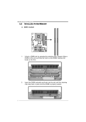
DDR3 module 1. Unlock a DIMM slot by pressing the retaining clips outward. Align a DIMM on the slot such that the notch on the DIMM matches the break on the Slot. 2. Insert the DIMM vertically and firmly into the slot until the retaining chip snap back in place and the DIMM is properly seated. 8 DDR3_A1 DDR3_B1 Motherboard Manual 2.3 INSTALLING SYSTEM MEMORY A.
DDR3 module 1. Unlock a DIMM slot by pressing the retaining clips outward. Align a DIMM on the slot such that the notch on the DIMM matches the break on the Slot. 2. Insert the DIMM vertically and firmly into the slot until the retaining chip snap back in place and the DIMM is properly seated. 8 DDR3_A1 DDR3_B1 Motherboard Manual 2.3 INSTALLING SYSTEM MEMORY A.
Setup Manual
Page 11
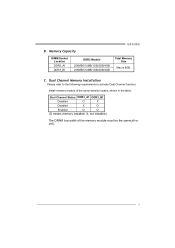
Dual Channel Status DDR3_A1 DDR3_B1 Disabled O X Disabled X O Enabled O O (O means memory installed; Dual Channel Memory Installation Please refer to the following requirements to activate Dual Channel function: Install memory module of the memory module must be the same(x8 or x16) 9 X, not installed.) The DRAM bus width of the same density in pairs, shown in the table. Memory Capacity G41U3G DIMM Socket Location DDR3_A1 DDR3_B1 DDR3 Module 256MB/512MB/1GB/2GB/4GB 256MB/512MB/1GB/2GB/4GB Total Memory Size Max is 8GB. B. C.
Dual Channel Status DDR3_A1 DDR3_B1 Disabled O X Disabled X O Enabled O O (O means memory installed; Dual Channel Memory Installation Please refer to the following requirements to activate Dual Channel function: Install memory module of the memory module must be the same(x8 or x16) 9 X, not installed.) The DRAM bus width of the same density in pairs, shown in the table. Memory Capacity G41U3G DIMM Socket Location DDR3_A1 DDR3_B1 DDR3 Module 256MB/512MB/1GB/2GB/4GB 256MB/512MB/1GB/2GB/4GB Total Memory Size Max is 8GB. B. C.

Setup Manual
Page 27
4.4 AMI BIOS BEEP CODE G41U3G Boot Block Beep Codes Number of Beeps Description 1 No media present. (Insert diskette in floppy drive A:) 2 "AMIBOOT.ROM" file not found in root directory of ... size error 13 BIOS ROM image mismatch (file layout does not match image present in flash device) POST BIOS Beep Codes Number of Beeps Description 1 Memory refresh timer error 3 Base memory read/write test error 6 Keyboard controller BAT command failed 7 General exception error (processor exception interrupt error) 8 Display...
4.4 AMI BIOS BEEP CODE G41U3G Boot Block Beep Codes Number of Beeps Description 1 No media present. (Insert diskette in floppy drive A:) 2 "AMIBOOT.ROM" file not found in root directory of ... size error 13 BIOS ROM image mismatch (file layout does not match image present in flash device) POST BIOS Beep Codes Number of Beeps Description 1 Memory refresh timer error 3 Base memory read/write test error 6 Keyboard controller BAT command failed 7 General exception error (processor exception interrupt error) 8 Display...


