Setup Manual
Page 2
... (CPU 6 2.2 FAN Headers 8 2.3 Installing System Memory 9 2.4 Connectors and Slots 11 Chapter 3: Headers & Jumpers Setup 14 3.1 How to Setup Jumpers 14 3.2 Detail Settings 14 Chapter 4: (Hybrid) CrossFireX Function 22 4.1 CrossFireX Requirements 22 4.2 CrossFireX Installation 22 4.3 Hybrid CrossFireX Requirements 23 4.4 Hybrid CrossFireX Installation 23 4.5 Operation Modes Supporting List 24 Chapter 5: RAID Functions 25 5.1 Operation System 25 5.2 Raid Arrays 25 5.3 How RAID Works 25 Chapter 6: T-Series BIOS & Software 29 6.1 T-Series BIOS 29...
... (CPU 6 2.2 FAN Headers 8 2.3 Installing System Memory 9 2.4 Connectors and Slots 11 Chapter 3: Headers & Jumpers Setup 14 3.1 How to Setup Jumpers 14 3.2 Detail Settings 14 Chapter 4: (Hybrid) CrossFireX Function 22 4.1 CrossFireX Requirements 22 4.2 CrossFireX Installation 22 4.3 Hybrid CrossFireX Requirements 23 4.4 Hybrid CrossFireX Installation 23 4.5 Operation Modes Supporting List 24 Chapter 5: RAID Functions 25 5.1 Operation System 25 5.2 Raid Arrays 25 5.3 How RAID Works 25 Chapter 6: T-Series BIOS & Software 29 6.1 T-Series BIOS 29...

Setup Manual
Page 3
Before you start installing the motherboard, please make sure you follow the instructions below: „ Prepare a dry and stable working environment with sufficient lighting. „ Always disconnect the computer from power outlet before operation. „ Before you for ATX Case X 1 User's Manual X 1 Fully Setup Driver CD X 1 DCCFX-P2 Paddle Card X 1 FDD Cable X 1 (optional) USB 2.0 Cable X1 (optional) S/PDIF out Cable X 1 (optional) Note: The package contents may damage the equipment. „ Keep the...
Before you start installing the motherboard, please make sure you follow the instructions below: „ Prepare a dry and stable working environment with sufficient lighting. „ Always disconnect the computer from power outlet before operation. „ Before you for ATX Case X 1 User's Manual X 1 Fully Setup Driver CD X 1 DCCFX-P2 Paddle Card X 1 FDD Cable X 1 (optional) USB 2.0 Cable X1 (optional) S/PDIF out Cable X 1 (optional) Note: The package contents may damage the equipment. „ Keep the...

Setup Manual
Page 4
... expansion cards PCI Express Gen2 x1 slot x2 Supports PCI-E Gen2 x1 expansion cards 2 H/W Monitor Fan Speed Controller Low Pin Count Interface ITE's "Smart Guardian" function DIMM Slots x 4 Dual Channel Mode DDR2 memory module Main Each DIMM supports 256MB/512MB/ Supports DDR2 533 / 667 / 800 Memory 1GB/2GB/4GB DDR2 Supports DDR2 1066 (by AM2+ CPU) Max Memory Capicity 16GB Registered DIMM and ECC DIMM is not supported Onboard side port memory 64MB (TA790GX A2+) Onboard side port memory 128MB (TA790GX 128M) Graphics Radeon HD 3300 Max Shared Video Memory...
... expansion cards PCI Express Gen2 x1 slot x2 Supports PCI-E Gen2 x1 expansion cards 2 H/W Monitor Fan Speed Controller Low Pin Count Interface ITE's "Smart Guardian" function DIMM Slots x 4 Dual Channel Mode DDR2 memory module Main Each DIMM supports 256MB/512MB/ Supports DDR2 533 / 667 / 800 Memory 1GB/2GB/4GB DDR2 Supports DDR2 1066 (by AM2+ CPU) Max Memory Capicity 16GB Registered DIMM and ECC DIMM is not supported Onboard side port memory 64MB (TA790GX A2+) Onboard side port memory 128MB (TA790GX 128M) Graphics Radeon HD 3300 Max Shared Video Memory...

Setup Manual
Page 5
...digital audio in function CPU Fan header x1 CPU Fan power supply (with Smart Fan function) System Fan header x2 System Fan Power supply CMOS clear header x1 Restore CMOS data to factory default USB connector x3 Each connector supports 2 front panel USB ports Serial port Connector x1 Connects to RS-232 Port Power Connector (24pin) x1 Connects to Power supply Power Connector (4pin) x2 Connects to Power supply PS/2 Keyboard x1 Connects to PS/2 Keyboard PS/2 Mouse x1 Connects to PS/2 Mouse HDMI port x1 Connect to HDTV Back Panel VGA port x1 Connect to D-SUB monitor...
...digital audio in function CPU Fan header x1 CPU Fan power supply (with Smart Fan function) System Fan header x2 System Fan Power supply CMOS clear header x1 Restore CMOS data to factory default USB connector x3 Each connector supports 2 front panel USB ports Serial port Connector x1 Connects to RS-232 Port Power Connector (24pin) x1 Connects to Power supply Power Connector (4pin) x2 Connects to Power supply PS/2 Keyboard x1 Connects to PS/2 Keyboard PS/2 Mouse x1 Connects to PS/2 Mouse HDMI port x1 Connect to HDTV Back Panel VGA port x1 Connect to D-SUB monitor...
Setup Manual
Page 13
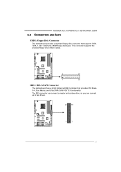
The IDE connector can connect a master and a slave drive, so you can connect up to two drives. 40 39 2 1 11 This connector supports the provided floppy drive ribbon cables. 2 34 1 33 IDE1: IDE/ATAPI Connector The motherboard has a 32-bit Enhanced IDE Controller that supports 360K, 720K, 1.2M, 1.44M and 2.88M floppy disk types. TA790GX A2+/TA790GX A2+ SE/TA790GX 128M 2.4 CONNECTORS AND SLOTS FDD1: Floppy Disk Connector The motherboard provides a standard floppy disk connector that provides PIO Mode 0~4, Bus Master, and Ultra DMA 33/66/100/133 functionality.
The IDE connector can connect a master and a slave drive, so you can connect up to two drives. 40 39 2 1 11 This connector supports the provided floppy drive ribbon cables. 2 34 1 33 IDE1: IDE/ATAPI Connector The motherboard has a 32-bit Enhanced IDE Controller that supports 360K, 720K, 1.2M, 1.44M and 2.88M floppy disk types. TA790GX A2+/TA790GX A2+ SE/TA790GX 128M 2.4 CONNECTORS AND SLOTS FDD1: Floppy Disk Connector The motherboard provides a standard floppy disk connector that provides PIO Mode 0~4, Bus Master, and Ultra DMA 33/66/100/133 functionality.
Setup Manual
Page 14
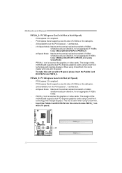
.... - When using CrossFireX, this motherboard supports dual PCI-Express graphics cards using CrossFireX. - This slot is master and runs with multiple displays. PEX16_1 slot is reserved for graphics or video cards. PCI-Express 2.0 compliant. - PEX16_2 slot is reserved for graphics or video cards. PCI-Express Gen2 supports a raw bit-rate of this slot is slave when using CrossFireX technology with x8 speed. - The design of 5.0Gb/s on the data pins. - 2X bandwidth over the PCI-Express 1.1 architecture. - PEX16_2: PCI-Express Gen2 x16 Slot (x8 Speed) - PEX16...
.... - When using CrossFireX, this motherboard supports dual PCI-Express graphics cards using CrossFireX. - This slot is master and runs with multiple displays. PEX16_1 slot is reserved for graphics or video cards. PCI-Express 2.0 compliant. - PEX16_2 slot is reserved for graphics or video cards. PCI-Express Gen2 supports a raw bit-rate of this slot is slave when using CrossFireX technology with x8 speed. - The design of 5.0Gb/s on the data pins. - 2X bandwidth over the PCI-Express 1.1 architecture. - PEX16_2: PCI-Express Gen2 x16 Slot (x8 Speed) - PEX16...

Setup Manual
Page 16
Motherboard Manual CHAPTER 3: HEADERS & JUMPERS SETUP 3.1 HOW TO SETUP JUMPERS The illustration shows how to connect the PC case's front panel switch functions. It allows user to set up jumpers. PWR_LED On/Off ++ - 9 16 1 +- 8 SPK RST HLED Pin Assignment 1 +5V 2 N/A 3 N/A 4 Speaker 5 HDD LED (+) 6 HDD LED (-) 7 Ground 8 Reset control Function Pin 9 Speaker 10 Connector 11 12 Hard drive 13 LED 14 Reset button 15 16 Assignment N/A N/A N/A Power LED (+) Power LED (+) Power LED (-) Power button Ground Function N/A N/A Power LED Power-on pins, the jumper ...
Motherboard Manual CHAPTER 3: HEADERS & JUMPERS SETUP 3.1 HOW TO SETUP JUMPERS The illustration shows how to connect the PC case's front panel switch functions. It allows user to set up jumpers. PWR_LED On/Off ++ - 9 16 1 +- 8 SPK RST HLED Pin Assignment 1 +5V 2 N/A 3 N/A 4 Speaker 5 HDD LED (+) 6 HDD LED (-) 7 Ground 8 Reset control Function Pin 9 Speaker 10 Connector 11 12 Hard drive 13 LED 14 Reset button 15 16 Assignment N/A N/A N/A Power LED (+) Power LED (+) Power LED (-) Power button Ground Function N/A N/A Power LED Power-on pins, the jumper ...
Setup Manual
Page 18
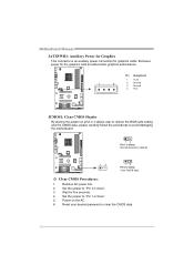
...: Clear CMOS Header By placing the jumper on the AC. 6. Wait for the graphics card provides better graphics performance. Exclusive power for five seconds. 4. Reset your desired password or clear the CMOS data. 16 Set the jumper to "Pin 2-3 close ". 5. Power on pin2-3, it allows user to restore the BIOS safe setting and the CMOS data, please carefully follow the procedures to "Pin 1-2 close ". 3. Motherboard Manual JATXPWR1: Auxiliary Power for Graphics This connector is an auxiliary power connection for graphics cards.
...: Clear CMOS Header By placing the jumper on the AC. 6. Wait for the graphics card provides better graphics performance. Exclusive power for five seconds. 4. Reset your desired password or clear the CMOS data. 16 Set the jumper to "Pin 2-3 close ". 5. Power on pin2-3, it allows user to restore the BIOS safe setting and the CMOS data, please carefully follow the procedures to "Pin 1-2 close ". 3. Motherboard Manual JATXPWR1: Auxiliary Power for Graphics This connector is an auxiliary power connection for graphics cards.
Setup Manual
Page 24
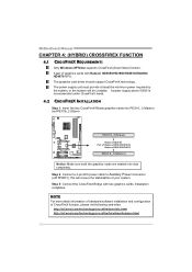
... stabilization of graphics cards with two graphics cards. Step 2: Connect a 4-pin ATX power cable to Auxiliary Power Connector (JATXPWR1), this will be unstable. Installation completes. NOTE For more detail information of hardware/software installation and configuration of Radeo n HD3850/HD3870 Radeo n HD4850/HD4870 PEX16_1(Master) Notice: Make sure both the graphics cards are seated into slots completely. Motherboard Manual CHAPTER 4: (HYBRID) CROSSFIREX FUNCTION 4.1 CROSSFIREX REQUIREMENTS Only Windows XP/Vista supports CrossFireX (Dual Video) function...
... stabilization of graphics cards with two graphics cards. Step 2: Connect a 4-pin ATX power cable to Auxiliary Power Connector (JATXPWR1), this will be unstable. Installation completes. NOTE For more detail information of hardware/software installation and configuration of Radeo n HD3850/HD3870 Radeo n HD4850/HD4870 PEX16_1(Master) Notice: Make sure both the graphics cards are seated into slots completely. Motherboard Manual CHAPTER 4: (HYBRID) CROSSFIREX FUNCTION 4.1 CROSSFIREX REQUIREMENTS Only Windows XP/Vista supports CrossFireX (Dual Video) function...

Setup Manual
Page 25
.... Step 2: Connect a 4-pin ATX power cable to Auxiliary Power Connector (JATXPWR1), this will be unstable. Step 3: In the graphics card configuration program, choose "Hybrid CrossFireX" function. P2 Paddle Card PEX16_1(Master) Radeon HD3450 Radeon HD3470 Notice: Make sure both cards are seated into PEX16_2 (Slave). TA790GX A2+/TA790GX A2+ SE/TA790GX 128M 4.3 HYBRID CROSSFIREX REQUIREMENTS Only Windows Vista supports Hybrid CrossFireX function. The graphics card driver should support Hybrid CrossFireX technology. A graphics card with Radeon...
.... Step 2: Connect a 4-pin ATX power cable to Auxiliary Power Connector (JATXPWR1), this will be unstable. Step 3: In the graphics card configuration program, choose "Hybrid CrossFireX" function. P2 Paddle Card PEX16_1(Master) Radeon HD3450 Radeon HD3470 Notice: Make sure both cards are seated into PEX16_2 (Slave). TA790GX A2+/TA790GX A2+ SE/TA790GX 128M 4.3 HYBRID CROSSFIREX REQUIREMENTS Only Windows Vista supports Hybrid CrossFireX function. The graphics card driver should support Hybrid CrossFireX technology. A graphics card with Radeon...
Setup Manual
Page 31
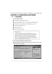
... from USB Flash Drive or FDD Self Recovery System (S.R.S) Smart Fan Function CMOS Reloading Program !! OverClock Navigator [Normal] =========== Automate OverClock System =========== Auto OverClock System [V6-Tech Engine] Manual OverClock System CPU Over Voltage [StartUp] Memory Over Voltage [1.95V] Chipset Over Voltage [1.15V] HT Over Voltage [1.20V] CPU Frequency [200] > CPU FID/VID Control > DRAM Timing Configuration > Hyper Transport Configuration > Memory Configuration Integrated Memory Test [Disabled] Normal Automate OverClock Manual OverClock Select Screen...
... from USB Flash Drive or FDD Self Recovery System (S.R.S) Smart Fan Function CMOS Reloading Program !! OverClock Navigator [Normal] =========== Automate OverClock System =========== Auto OverClock System [V6-Tech Engine] Manual OverClock System CPU Over Voltage [StartUp] Memory Over Voltage [1.95V] Chipset Over Voltage [1.15V] HT Over Voltage [1.20V] CPU Frequency [200] > CPU FID/VID Control > DRAM Timing Configuration > Hyper Transport Configuration > Memory Configuration Integrated Memory Test [Disabled] Normal Automate OverClock Manual OverClock Select Screen...

Setup Manual
Page 32
... overclock users. Main Advanced PCIPnP BIOS SETUP UTILITY Boot Chipset T-Series Exit T-Series Settings Options WARNING: Setting wrong values in below sections may cause system to malfunction. OverClock Navigator [Manual OverClock] =========== Automate OverClock System =========== Auto OverClock System [V6-Tech Engine] Manual OverClock System CPU Over Voltage [StartUp] Memory Over Voltage [1.95V] Chipset Over Voltage [1.15V] HT Over Voltage [1.20V] CPU Frequency [200] > CPU FID/VID Control > DRAM Timing Configuration > Hyper Transport Configuration > Memory...
... overclock users. Main Advanced PCIPnP BIOS SETUP UTILITY Boot Chipset T-Series Exit T-Series Settings Options WARNING: Setting wrong values in below sections may cause system to malfunction. OverClock Navigator [Manual OverClock] =========== Automate OverClock System =========== Auto OverClock System [V6-Tech Engine] Manual OverClock System CPU Over Voltage [StartUp] Memory Over Voltage [1.95V] Chipset Over Voltage [1.15V] HT Over Voltage [1.20V] CPU Frequency [200] > CPU FID/VID Control > DRAM Timing Configuration > Hyper Transport Configuration > Memory...
Setup Manual
Page 33
.../VID Control > DRAM Timing Configuration > Hyper Transport Configuration > Memory Configuration Integrated Memory Test [Disabled] Normal Automate OverClock Manual OverClock Select Screen Select Item +- TA790GX A2+/TA790GX A2+ SE/TA790GX 128M CPU Frequency CPU Frequency is directly in proportion to raise the system performance in a single step. Memory Configuration Enter this function for more advanced DRAM clock settings. We also would not guarantee any hardware damage which may cause system to malfunction. Main Advanced PCIPnP BIOS SETUP UTILITY Boot Chipset T-Series Exit...
.../VID Control > DRAM Timing Configuration > Hyper Transport Configuration > Memory Configuration Integrated Memory Test [Disabled] Normal Automate OverClock Manual OverClock Select Screen Select Item +- TA790GX A2+/TA790GX A2+ SE/TA790GX 128M CPU Frequency CPU Frequency is directly in proportion to raise the system performance in a single step. Memory Configuration Enter this function for more advanced DRAM clock settings. We also would not guarantee any hardware damage which may cause system to malfunction. Main Advanced PCIPnP BIOS SETUP UTILITY Boot Chipset T-Series Exit...

Setup Manual
Page 35
...The default setting under "Overclocking Navigator Engine" item. Main Advanced PCIPnP BIOS SETUP UTILITY Boot Chipset T-Series Exit T-Series Settings Options WARNING: Setting wrong values in below sections may cause system to malfunction. Enabled Disabled OverClock Navigator [Normal] =========== Automate OverClock System =========== Auto OverClock System [V6-Tech Engine] Manual OverClock System CPU Over Voltage [StartUp] Memory Over Voltage [1.95V] Chipset Over Voltage [1.15V] HT Over Voltage [1.20V] CPU Frequency [200] > CPU FID/VID Control > DRAM Timing...
...The default setting under "Overclocking Navigator Engine" item. Main Advanced PCIPnP BIOS SETUP UTILITY Boot Chipset T-Series Exit T-Series Settings Options WARNING: Setting wrong values in below sections may cause system to malfunction. Enabled Disabled OverClock Navigator [Normal] =========== Automate OverClock System =========== Auto OverClock System [V6-Tech Engine] Manual OverClock System CPU Over Voltage [StartUp] Memory Over Voltage [1.95V] Chipset Over Voltage [1.15V] HT Over Voltage [1.20V] CPU Frequency [200] > CPU FID/VID Control > DRAM Timing...
Setup Manual
Page 36
... appears. z This utility only allows storage device with BIO-Flasher 1. BIO-Flasher BIO-Flasher is built in the BIOS chip. Then, save the BIOS file into a USB pen drive or a floppy disk. 3. The BIO-Flasher is a BIOS flashing utility providing you to system boot failure. 34 The utility will show the BIOS files and their respective information. Select the device contains the BIOS file and press to perform the BIOS update process. 6. Press to update your BIOS via USB pen drive or floppy disk. Motherboard Manual C.
... appears. z This utility only allows storage device with BIO-Flasher 1. BIO-Flasher BIO-Flasher is built in the BIOS chip. Then, save the BIOS file into a USB pen drive or a floppy disk. 3. The BIO-Flasher is a BIOS flashing utility providing you to system boot failure. 34 The utility will show the BIOS files and their respective information. Select the device contains the BIOS file and press to perform the BIOS update process. 6. Press to update your BIOS via USB pen drive or floppy disk. Motherboard Manual C.

Setup Manual
Page 37
... BIOS SETUP UTILITY Smart Fan Configuration CPU Smart Fan Smart Fan Calibration Control Mode Fan Ctrl OFF(oC) Fan Ctrl On(oC) Fan Ctrl Start value Fan Ctrl Sensitive [Disabled] When you choice [Auto] ,[3Pin] or [4Pin], please run the calibration to define the Fan parameters for Smart Fan control Select Screen Select Item +- Change Option F1 General Help F10 Save and Exit ESC Exit vxx.xx (C)Copyright 1985-200x, American Megatrends, Inc. 35 TA790GX A2+/TA790GX A2+ SE/TA790GX 128M D. Fan speed...
... BIOS SETUP UTILITY Smart Fan Configuration CPU Smart Fan Smart Fan Calibration Control Mode Fan Ctrl OFF(oC) Fan Ctrl On(oC) Fan Ctrl Start value Fan Ctrl Sensitive [Disabled] When you choice [Auto] ,[3Pin] or [4Pin], please run the calibration to define the Fan parameters for Smart Fan control Select Screen Select Item +- Change Option F1 General Help F10 Save and Exit ESC Exit vxx.xx (C)Copyright 1985-200x, American Megatrends, Inc. 35 TA790GX A2+/TA790GX A2+ SE/TA790GX 128M D. Fan speed...

Setup Manual
Page 38
... the set value, the CPU/System fan will raise the speed of 1. CMOS Reloading Program It allows users to save different CMOS settings into BIOS-ROM. Main Advanced PCIPnP Exit Options Save Changes and Exit Discard Changes and Exit Discard Changes Load Optimal Defaults CMOS Backup Function Security Settings > Security BIOS SETUP UTILITY Boot Chipset T-Series Exit CMOS Backup Func CMOS Data Reload CMOS Data Save Select Screen Select Item EnterGo to personal preference. Motherboard Manual Smart Fan Calibration Choose this set value. Fan Ctrl...
... the set value, the CPU/System fan will raise the speed of 1. CMOS Reloading Program It allows users to save different CMOS settings into BIOS-ROM. Main Advanced PCIPnP Exit Options Save Changes and Exit Discard Changes and Exit Discard Changes Load Optimal Defaults CMOS Backup Function Security Settings > Security BIOS SETUP UTILITY Boot Chipset T-Series Exit CMOS Backup Func CMOS Data Reload CMOS Data Save Select Screen Select Item EnterGo to personal preference. Motherboard Manual Smart Fan Calibration Choose this set value. Fan Ctrl...
Setup Manual
Page 45
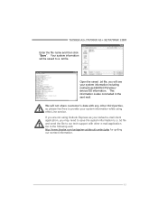
... service. Go to our tech support with any other e-mail application. This information is also concluded in the sent mail. TA790GX A2+/TA790GX A2+ SE/TA790GX 128M Enter the file name and then click "Save". We will be saved to provide your system information while using Outlook Express as your default e-mail client application, you will see your system information including motherboard/BIOS/CPU/video/ device...
... service. Go to our tech support with any other e-mail application. This information is also concluded in the sent mail. TA790GX A2+/TA790GX A2+ SE/TA790GX 128M Enter the file name and then click "Save". We will be saved to provide your system information while using Outlook Express as your default e-mail client application, you will see your system information including motherboard/BIOS/CPU/video/ device...

Setup Manual
Page 48
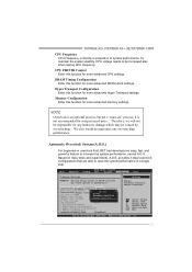
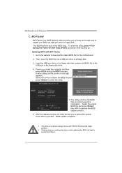
... Online Update button, the utility will ask you to proceed. If there is connected to be slightly different from internet. While the system boots up and the full screen logo shows, press key to exit BIOS setup. The information and pictures described above about the T-Series software are for AMI BIOS only) Automatically download and update the latest BIOS via internet; In the BIOS setup, use the Load Optimized Defaults...
... Online Update button, the utility will ask you to proceed. If there is connected to be slightly different from internet. While the system boots up and the full screen logo shows, press key to exit BIOS setup. The information and pictures described above about the T-Series software are for AMI BIOS only) Automatically download and update the latest BIOS via internet; In the BIOS setup, use the Load Optimized Defaults...
Setup Manual
Page 51
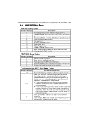
... are used for recovery 4 Flash Programming successful 5 File read error 7 No Flash EPROM detected 10 Flash Erase error 11 Flash Program error 12 "AMIBOOT.ROM" file size error 13 BIOS ROM image mismatch (file layout does not match image present in flash device) POST BIOS Beep Codes Number of Beeps Description 1 Memory refresh timer error 3 Base memory read/write test error 6 Keyboard controller BAT command failed 7 General exception error (processor exception interrupt error) 8 Display memory error (system video adapter) Troubleshooting POST BIOS Beep Codes Number...
... are used for recovery 4 Flash Programming successful 5 File read error 7 No Flash EPROM detected 10 Flash Erase error 11 Flash Program error 12 "AMIBOOT.ROM" file size error 13 BIOS ROM image mismatch (file layout does not match image present in flash device) POST BIOS Beep Codes Number of Beeps Description 1 Memory refresh timer error 3 Base memory read/write test error 6 Keyboard controller BAT command failed 7 General exception error (processor exception interrupt error) 8 Display memory error (system video adapter) Troubleshooting POST BIOS Beep Codes Number...


