Setup Manual
Page 1
... beforehand. Further the vendor reserves the right to revise this publication and to make changes to the contents here without obligation to notify any purpose. TA790GX A2+/TA790GX A2+ SE/TA790GX 128M Setup Manual FCC Information and Copyright This equipment has been tested and found in this user's manual. This equipment generates, uses, and can radiate...
... beforehand. Further the vendor reserves the right to revise this publication and to make changes to the contents here without obligation to notify any purpose. TA790GX A2+/TA790GX A2+ SE/TA790GX 128M Setup Manual FCC Information and Copyright This equipment has been tested and found in this user's manual. This equipment generates, uses, and can radiate...

Setup Manual
Page 3
... on the edge, do not try to bend or flex the board. „ Do not leave any unfastened small parts inside the case after installation. TA790GX A2+/TA790GX A2+ SE/TA790GX 128M CHAPTER 1: INTRODUCTION 1.1 BEFORE YOU START Thank you take the motherboard out from anti-static bag, ground yourself properly by area or your motherboard version...
... on the edge, do not try to bend or flex the board. „ Do not leave any unfastened small parts inside the case after installation. TA790GX A2+/TA790GX A2+ SE/TA790GX 128M CHAPTER 1: INTRODUCTION 1.1 BEFORE YOU START Thank you take the motherboard out from anti-static bag, ground yourself properly by area or your motherboard version...

Setup Manual
Page 4
... Supports DDR2 1066 (by AM2+ CPU) Max Memory Capicity 16GB Registered DIMM and ECC DIMM is not supported Onboard side port memory 64MB (TA790GX A2+) Onboard side port memory 128MB (TA790GX 128M) Graphics Radeon HD 3300 Max Shared Video Memory is 512MB DX10/UVD/HDCP support (Hybrid) CrossFireX support (by ATI driver) IDE AMD...
... Supports DDR2 1066 (by AM2+ CPU) Max Memory Capicity 16GB Registered DIMM and ECC DIMM is not supported Onboard side port memory 64MB (TA790GX A2+) Onboard side port memory 128MB (TA790GX 128M) Graphics Radeon HD 3300 Max Shared Video Memory is 512MB DX10/UVD/HDCP support (Hybrid) CrossFireX support (by ATI driver) IDE AMD...

Setup Manual
Page 5
TA790GX A2+/TA790GX A2+ SE/TA790GX 128M SPEC Floppy connector x1 Each connector supports 2 Floppy drives Printer Port connector x1 Each connector supports 1 Printer port IDE Connector x1 Each connector supports 2 IDE ... to USB devices Audio Jack x6 Provide Audio-In/Out and microphone connection Board Size 225 mm (W) x 305 mm (L) ATX OS Support Windows XP / VISTA Biostar Reserves the right to add or remove support for any OS With or without notice. 3
TA790GX A2+/TA790GX A2+ SE/TA790GX 128M SPEC Floppy connector x1 Each connector supports 2 Floppy drives Printer Port connector x1 Each connector supports 1 Printer port IDE Connector x1 Each connector supports 2 IDE ... to USB devices Audio Jack x6 Provide Audio-In/Out and microphone connection Board Size 225 mm (W) x 305 mm (L) ATX OS Support Windows XP / VISTA Biostar Reserves the right to add or remove support for any OS With or without notice. 3

Setup Manual
Page 7
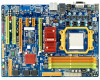
TA790GX A2+/TA790GX A2+ SE/TA790GX 128M 1.5 MOTHERBOARD LAYOUT JKBMS1 JATXPWR3 JCFAN1 JHDMI1 JATXPWR2 Socket AM2+ DVI VGA DIMMA1 DIMMB1 DIMMA2 DIMMB2 JUSB1 JUSBLAN1 JAUDIO2 J ATXPWR1 AMD 790GX JUSB V1 LAN JNFAN1 PEX16_2 PEX1_1 PEX1_2 BAT1 AMD SB750 SATA5-6 SATA3-4 IDE1 PEX16_1 LED_D1 LED_D2 Codec JSP DIF_ IN1 PCI1 Super I/O JAUDIOF1 JSPDIF_OUT1 JCDIN1 PCI2 JPRNT1 J COM1 JUSBV2 JUSB5 JUSB 3 JSFAN1 J USB4 Note: ■ represents the 1st pin. BIOS SATA1-2 JCMOS1 FDD1 JPANEL1 RSTSW1 PWRSW1 5
TA790GX A2+/TA790GX A2+ SE/TA790GX 128M 1.5 MOTHERBOARD LAYOUT JKBMS1 JATXPWR3 JCFAN1 JHDMI1 JATXPWR2 Socket AM2+ DVI VGA DIMMA1 DIMMB1 DIMMA2 DIMMB2 JUSB1 JUSBLAN1 JAUDIO2 J ATXPWR1 AMD 790GX JUSB V1 LAN JNFAN1 PEX16_2 PEX1_1 PEX1_2 BAT1 AMD SB750 SATA5-6 SATA3-4 IDE1 PEX16_1 LED_D1 LED_D2 Codec JSP DIF_ IN1 PCI1 Super I/O JAUDIOF1 JSPDIF_OUT1 JCDIN1 PCI2 JPRNT1 J COM1 JUSBV2 JUSB5 JUSB 3 JSFAN1 J USB4 Note: ■ represents the 1st pin. BIOS SATA1-2 JCMOS1 FDD1 JPANEL1 RSTSW1 PWRSW1 5
Setup Manual
Page 9
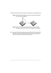
... your system, and update the latest BIOS from our website for AM2+ CPUs support. 7 Step 5: Put the CPU Fan on the CPU and buckle it. TA790GX A2+/TA790GX A2+ SE/TA790GX 128M Step 4: Hold the CPU down firmly, and then close the lever toward direct B to the latest version while using new AM2+ CPUs.
... your system, and update the latest BIOS from our website for AM2+ CPUs support. 7 Step 5: Put the CPU Fan on the CPU and buckle it. TA790GX A2+/TA790GX A2+ SE/TA790GX 128M Step 4: Hold the CPU down firmly, and then close the lever toward direct B to the latest version while using new AM2+ CPUs.
Setup Manual
Page 11
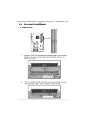
Align a DIMM on the slot such that the notch on the DIMM matches the break on the Slot. 2. Unlock a DIMM slot by pressing the retaining clips outward. DIMMA 1 DIMMB 1 DIMMA 2 DIMMB 2 TA790GX A2+/TA790GX A2+ SE/TA790GX 128M 2.3 INSTALLING SYSTEM MEMORY A. DDR2 Modules 1. Insert the DIMM vertically and firmly into the slot until the retaining chip snap back in place and the DIMM is properly seated. 9
Align a DIMM on the slot such that the notch on the DIMM matches the break on the Slot. 2. Unlock a DIMM slot by pressing the retaining clips outward. DIMMA 1 DIMMB 1 DIMMA 2 DIMMB 2 TA790GX A2+/TA790GX A2+ SE/TA790GX 128M 2.3 INSTALLING SYSTEM MEMORY A. DDR2 Modules 1. Insert the DIMM vertically and firmly into the slot until the retaining chip snap back in place and the DIMM is properly seated. 9
Setup Manual
Page 13
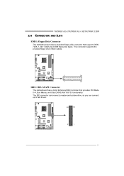
This connector supports the provided floppy drive ribbon cables. 2 34 1 33 IDE1: IDE/ATAPI Connector The motherboard has a 32-bit Enhanced IDE Controller that supports 360K, 720K, 1.2M, 1.44M and 2.88M floppy disk types. The IDE connector can connect a master and a slave drive, so you can connect up to two drives. 40 39 2 1 11 TA790GX A2+/TA790GX A2+ SE/TA790GX 128M 2.4 CONNECTORS AND SLOTS FDD1: Floppy Disk Connector The motherboard provides a standard floppy disk connector that provides PIO Mode 0~4, Bus Master, and Ultra DMA 33/66/100/133 functionality.
This connector supports the provided floppy drive ribbon cables. 2 34 1 33 IDE1: IDE/ATAPI Connector The motherboard has a 32-bit Enhanced IDE Controller that supports 360K, 720K, 1.2M, 1.44M and 2.88M floppy disk types. The IDE connector can connect a master and a slave drive, so you can connect up to two drives. 40 39 2 1 11 TA790GX A2+/TA790GX A2+ SE/TA790GX 128M 2.4 CONNECTORS AND SLOTS FDD1: Floppy Disk Connector The motherboard provides a standard floppy disk connector that provides PIO Mode 0~4, Bus Master, and Ultra DMA 33/66/100/133 functionality.

Setup Manual
Page 15
PCI-Express 2.0 compliant. - Data transfer bandwidth up to 500MB/s per direction; 1GB/s in total. - PEX1_ 1 PE X1_ 2 PCI1~PCI2: Peripheral Component Interconnect Slots This motherboard is designated as 32 bits. PCI-Express Gen2 supports a raw bit-rate of 5.0Gb/s on the data pins. - 2X bandwidth over the PCI-Express 1.1 architecture. This PCI slot is equipped with 2 standard PCI slots. TA790GX A2+/TA790GX A2+ SE/TA790GX 128M PEX1_1/PEX1_2: PCI-Express Gen2 x1 Slots - PCI1 PCI2 13 PCI stands for Peripheral Component Interconnect, and it is a bus standard for expansion cards.
PCI-Express 2.0 compliant. - Data transfer bandwidth up to 500MB/s per direction; 1GB/s in total. - PEX1_ 1 PE X1_ 2 PCI1~PCI2: Peripheral Component Interconnect Slots This motherboard is designated as 32 bits. PCI-Express Gen2 supports a raw bit-rate of 5.0Gb/s on the data pins. - 2X bandwidth over the PCI-Express 1.1 architecture. This PCI slot is equipped with 2 standard PCI slots. TA790GX A2+/TA790GX A2+ SE/TA790GX 128M PEX1_1/PEX1_2: PCI-Express Gen2 x1 Slots - PCI1 PCI2 13 PCI stands for Peripheral Component Interconnect, and it is a bus standard for expansion cards.
Setup Manual
Page 17
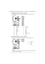
TA790GX A2+/TA790GX A2+ SE/TA790GX 128M JATXPWR2: ATX Power Source Connector This connector allows user to connect 24-pin power connector on the ATX power supply. 12 24 1 13 Pin Assignment ...
TA790GX A2+/TA790GX A2+ SE/TA790GX 128M JATXPWR2: ATX Power Source Connector This connector allows user to connect 24-pin power connector on the ATX power supply. 12 24 1 13 Pin Assignment ...

Setup Manual
Page 19
... header allows user to SATA Controller with 6 channels SATA interface, it satisfies the SATA 2.0 spec and with internal USB devices, like USB card reader. TA790GX A2+/TA790GX A2+ SE/TA790GX 128M SATA1-2/SATA3-4/SATA5-6: Serial ATA Connectors The motherboard has a PCI to connect additional USB cable on the PC front panel, and also can be connected...
... header allows user to SATA Controller with 6 channels SATA interface, it satisfies the SATA 2.0 spec and with internal USB devices, like USB card reader. TA790GX A2+/TA790GX A2+ SE/TA790GX 128M SATA1-2/SATA3-4/SATA5-6: Serial ATA Connectors The motherboard has a PCI to connect additional USB cable on the PC front panel, and also can be connected...

Setup Manual
Page 21
TA790GX A2+/TA790GX A2+ SE/TA790GX 128M JCDIN1: CD-ROM Audio-in Connector This connector allows user to connect the audio source from the variaty devices, like CD-ROM, DVD-ROM, PCI ...
TA790GX A2+/TA790GX A2+ SE/TA790GX 128M JCDIN1: CD-ROM Audio-in Connector This connector allows user to connect the audio source from the variaty devices, like CD-ROM, DVD-ROM, PCI ...

Setup Manual
Page 23
Please refer to show system status. RSTSW1 PWRSW1 PWRSW1: This is an on diagnostics. Memory Error VGA Error Normal On-Board Buttons There are 2 LED indicators on the motherboard to the table below for different messages: LED_D2 OFF OFF ON ON LED_D1 OFF ON OFF ON Message Abnormal: CPU / Chipset error. LED_D1 LED_D2 LED_D1 and LED_D2: These 2 LED indicate system power on -board Reset button. 21 RSTSW1: This is an on -board buttons. TA790GX A2+/TA790GX A2+ SE/TA790GX 128M On-Board LED Indicators There are 2 on -board Power Switch button.
Please refer to show system status. RSTSW1 PWRSW1 PWRSW1: This is an on diagnostics. Memory Error VGA Error Normal On-Board Buttons There are 2 LED indicators on the motherboard to the table below for different messages: LED_D2 OFF OFF ON ON LED_D1 OFF ON OFF ON Message Abnormal: CPU / Chipset error. LED_D1 LED_D2 LED_D1 and LED_D2: These 2 LED indicate system power on -board Reset button. 21 RSTSW1: This is an on -board buttons. TA790GX A2+/TA790GX A2+ SE/TA790GX 128M On-Board LED Indicators There are 2 on -board Power Switch button.

Setup Manual
Page 25
TA790GX A2+/TA790GX A2+ SE/TA790GX 128M 4.3 HYBRID CROSSFIREX REQUIREMENTS Only Windows Vista supports Hybrid CrossFireX function. P2 Paddle Card PEX16_1(Master) Radeon HD3450 Radeon HD3470 Notice: Make sure both cards are ...
TA790GX A2+/TA790GX A2+ SE/TA790GX 128M 4.3 HYBRID CROSSFIREX REQUIREMENTS Only Windows Vista supports Hybrid CrossFireX function. P2 Paddle Card PEX16_1(Master) Radeon HD3450 Radeon HD3470 Notice: Make sure both cards are ...
Setup Manual
Page 27
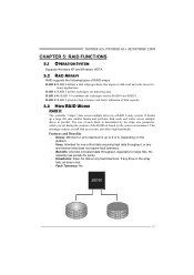
... the array fails, all data is up a large file into smaller blocks and performs disk reads and writes across multiple drives in a RAID 0 array system. TA790GX A2+/TA790GX A2+ SE/TA790GX 128M CHAPTER 5: RAID FUNCTIONS 5.1 OPERATION SYSTEM Supports Windows XP and Windows VISTA. 5.2 RAID ARRAYS RAID supports the following types of disk capacity. 5.3 HOW RAID WORKS...
... the array fails, all data is up a large file into smaller blocks and performs disk reads and writes across multiple drives in a RAID 0 array system. TA790GX A2+/TA790GX A2+ SE/TA790GX 128M CHAPTER 5: RAID FUNCTIONS 5.1 OPERATION SYSTEM Supports Windows XP and Windows VISTA. 5.2 RAID ARRAYS RAID supports the following types of disk capacity. 5.3 HOW RAID WORKS...

Setup Manual
Page 29
... level 1. Fault Tolerance: Yes. Resulting in an array, and allows for spare disks. Drawbacks: Requires twice the available disk space for automatic redundancy. TA790GX A2+/TA790GX A2+ SE/TA790GX 128M RAID 1+0: RAID 1 drives can be simultaneously used with other RAID levels in a RAID 1+0 solution for improved resiliency, performance and rebuild performance.
... level 1. Fault Tolerance: Yes. Resulting in an array, and allows for spare disks. Drawbacks: Requires twice the available disk space for automatic redundancy. TA790GX A2+/TA790GX A2+ SE/TA790GX 128M RAID 1+0: RAID 1 drives can be simultaneously used with other RAID levels in a RAID 1+0 solution for improved resiliency, performance and rebuild performance.
Setup Manual
Page 31
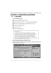
... Manual in this manual. A. WARNING !! Change Option F1 General Help F10 Save and Exit ESC Exit vxx.xx (C)Copyright 1985-200x, American Megatrends, Inc. 29 TA790GX A2+/TA790GX A2+ SE/TA790GX 128M CHAPTER 6: T-SERIES BIOS & SOFTWARE 6.1 T-SERIES BIOS T-Series BIOS Features Overclocking Navigator Engine (O.N.E.) Memory Integration Test (M.I.T., under Overclock Navigator Engine) BIO-Flasher: Update BIOS file...
... Manual in this manual. A. WARNING !! Change Option F1 General Help F10 Save and Exit ESC Exit vxx.xx (C)Copyright 1985-200x, American Megatrends, Inc. 29 TA790GX A2+/TA790GX A2+ SE/TA790GX 128M CHAPTER 6: T-SERIES BIOS & SOFTWARE 6.1 T-SERIES BIOS T-Series BIOS Features Overclocking Navigator Engine (O.N.E.) Memory Integration Test (M.I.T., under Overclock Navigator Engine) BIO-Flasher: Update BIOS file...
Setup Manual
Page 33
... experiments, A.O.S. it is not recommended for more advanced memory settings. To maintain the system stability, CPU voltage needs to increase the system performance, named A.O.S. TA790GX A2+/TA790GX A2+ SE/TA790GX 128M CPU Frequency CPU Frequency is directly in below sections may be caused by overclocking. DRAM Timing Configuration Enter this function for any overclocking performance. Change...
... experiments, A.O.S. it is not recommended for more advanced memory settings. To maintain the system stability, CPU voltage needs to increase the system performance, named A.O.S. TA790GX A2+/TA790GX A2+ SE/TA790GX 128M CPU Frequency CPU Frequency is directly in below sections may be caused by overclocking. DRAM Timing Configuration Enter this function for any overclocking performance. Change...

Setup Manual
Page 35
TA790GX A2+/TA790GX A2+ SE/TA790GX 128M Notices: Not all types of AMD CPU perform above overclock setting ideally; MIT allows users to activate this item is under "Overclocking Navigator Engine" item. ...
TA790GX A2+/TA790GX A2+ SE/TA790GX 128M Notices: Not all types of AMD CPU perform above overclock setting ideally; MIT allows users to activate this item is under "Overclocking Navigator Engine" item. ...

Setup Manual
Page 37
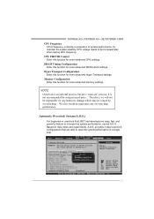
... values in the default BIOS setting, and all overclock settings will protect CPU/System from overheat problem and maintain the system temperature at a safe level. TA790GX A2+/TA790GX A2+ SE/TA790GX 128M D. However, it can 't be re-configured. E. Fan speed. Change Option F1 General Help F10 Save and Exit ESC Exit vxx.xx (C)Copyright 1985-200x...
... values in the default BIOS setting, and all overclock settings will protect CPU/System from overheat problem and maintain the system temperature at a safe level. TA790GX A2+/TA790GX A2+ SE/TA790GX 128M D. However, it can 't be re-configured. E. Fan speed. Change Option F1 General Help F10 Save and Exit ESC Exit vxx.xx (C)Copyright 1985-200x...
