Setup Manual
Page 2
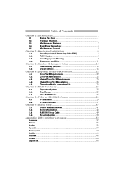
... 1: Introduction 1 1.1 Before You Start 1 1.2 Package Checklist 1 1.3 Motherboard Features 2 1.4 Rear Panel Connectors 4 1.5 Motherboard Layout 5 Chapter 2: Hardware Installation 6 2.1 Installing Central Processing Unit (CPU 6 2.2 FAN Headers 8 2.3 Installing System Memory 9 2.4 Connectors and Slots 11 Chapter 3: Headers & Jumpers Setup 14 3.1 How to Setup Jumpers 14 3.2 Detail Settings 14 Chapter 4: (Hybrid) CrossFireX Function 22 4.1 CrossFireX Requirements 22...
... 1: Introduction 1 1.1 Before You Start 1 1.2 Package Checklist 1 1.3 Motherboard Features 2 1.4 Rear Panel Connectors 4 1.5 Motherboard Layout 5 Chapter 2: Hardware Installation 6 2.1 Installing Central Processing Unit (CPU 6 2.2 FAN Headers 8 2.3 Installing System Memory 9 2.4 Connectors and Slots 11 Chapter 3: Headers & Jumpers Setup 14 3.1 How to Setup Jumpers 14 3.2 Detail Settings 14 Chapter 4: (Hybrid) CrossFireX Function 22 4.1 CrossFireX Requirements 22...

Setup Manual
Page 4
.../2GB/4GB DDR2 Supports DDR2 1066 (by AM2+ CPU) Max Memory Capicity 16GB Registered DIMM and ECC DIMM is not supported Onboard side port memory 64MB (TA790GX A2+) Onboard side port memory 128MB (TA790GX 128M) Graphics Radeon HD 3300 Max Shared Video Memory is 512MB DX10/UVD/HDCP support (Hybrid) CrossFireX support (by ATI driver) IDE AMD...
.../2GB/4GB DDR2 Supports DDR2 1066 (by AM2+ CPU) Max Memory Capicity 16GB Registered DIMM and ECC DIMM is not supported Onboard side port memory 64MB (TA790GX A2+) Onboard side port memory 128MB (TA790GX 128M) Graphics Radeon HD 3300 Max Shared Video Memory is 512MB DX10/UVD/HDCP support (Hybrid) CrossFireX support (by ATI driver) IDE AMD...
Setup Manual
Page 11
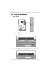
Align a DIMM on the slot such that the notch on the DIMM matches the break on the Slot. 2. Unlock a DIMM slot by pressing the retaining clips outward. DIMMA 1 DIMMB 1 DIMMA 2 DIMMB 2 TA790GX A2+/TA790GX A2+ SE/TA790GX 128M 2.3 INSTALLING SYSTEM MEMORY A. Insert the DIMM vertically and firmly into the slot until the retaining chip snap back in place and the DIMM is properly seated. 9 DDR2 Modules 1.
Align a DIMM on the slot such that the notch on the DIMM matches the break on the Slot. 2. Unlock a DIMM slot by pressing the retaining clips outward. DIMMA 1 DIMMB 1 DIMMA 2 DIMMB 2 TA790GX A2+/TA790GX A2+ SE/TA790GX 128M 2.3 INSTALLING SYSTEM MEMORY A. Insert the DIMM vertically and firmly into the slot until the retaining chip snap back in place and the DIMM is properly seated. 9 DDR2 Modules 1.

Setup Manual
Page 12
... DIMMB1 DIMMA2 DIMMB2 Enabled O O X X Enabled X X O O Enabled O O O O (O means memory installed, X means memory not installed.) The DRAM bus width of the memory module must meet the following requirements: Install memory module of the motherboard, the memory module must be the same (x8 or x16) 10 Motherboard Manual B. Dual Channel Memory installation To trigger the Dual Channel function of...
... DIMMB1 DIMMA2 DIMMB2 Enabled O O X X Enabled X X O O Enabled O O O O (O means memory installed, X means memory not installed.) The DRAM bus width of the memory module must meet the following requirements: Install memory module of the motherboard, the memory module must be the same (x8 or x16) 10 Motherboard Manual B. Dual Channel Memory installation To trigger the Dual Channel function of...

Setup Manual
Page 23
RSTSW1: This is an on-board Power Switch button. Memory Error VGA Error Normal On-Board Buttons There are 2 LED indicators on -board buttons. RSTSW1 PWRSW1 PWRSW1: This is an on diagnostics. TA790GX A2+/TA790GX A2+ SE/TA790GX 128M On-Board LED Indicators There are 2 on the motherboard to the table below for different messages: LED_D2 OFF OFF ON ON LED_D1 OFF ON OFF ON Message Abnormal: CPU / Chipset error. Please refer to show system status. LED_D1 LED_D2 LED_D1 and LED_D2: These 2 LED indicate system power on -board Reset button. 21
RSTSW1: This is an on-board Power Switch button. Memory Error VGA Error Normal On-Board Buttons There are 2 LED indicators on -board buttons. RSTSW1 PWRSW1 PWRSW1: This is an on diagnostics. TA790GX A2+/TA790GX A2+ SE/TA790GX 128M On-Board LED Indicators There are 2 on the motherboard to the table below for different messages: LED_D2 OFF OFF ON ON LED_D1 OFF ON OFF ON Message Abnormal: CPU / Chipset error. Please refer to show system status. LED_D1 LED_D2 LED_D1 and LED_D2: These 2 LED indicate system power on -board Reset button. 21
Setup Manual
Page 31
... [200] > CPU FID/VID Control > DRAM Timing Configuration > Hyper Transport Configuration > Memory Configuration Integrated Memory Test [Disabled] Normal Automate OverClock Manual OverClock Select Screen Select Item +- TA790GX A2+/TA790GX A2+ SE/TA790GX 128M CHAPTER 6: T-SERIES BIOS & SOFTWARE 6.1 T-SERIES BIOS T-Series BIOS Features Overclocking Navigator Engine (O.N.E.) Memory Integration Test (M.I.T., under Overclock Navigator Engine) BIO-Flasher: Update BIOS file...
... [200] > CPU FID/VID Control > DRAM Timing Configuration > Hyper Transport Configuration > Memory Configuration Integrated Memory Test [Disabled] Normal Automate OverClock Manual OverClock Select Screen Select Item +- TA790GX A2+/TA790GX A2+ SE/TA790GX 128M CHAPTER 6: T-SERIES BIOS & SOFTWARE 6.1 T-SERIES BIOS T-Series BIOS Features Overclocking Navigator Engine (O.N.E.) Memory Integration Test (M.I.T., under Overclock Navigator Engine) BIO-Flasher: Update BIOS file...

Setup Manual
Page 32
...20V] CPU Frequency [200] > CPU FID/VID Control > DRAM Timing Configuration > Hyper Transport Configuration > Memory Configuration Integrated Memory Test [Disabled] Normal Automate OverClock Manual OverClock Select Screen Select Item +- OverClock Navigator [Manual OverClock] =========== Automate...20V] CPU Frequency [200] > CPU FID/VID Control > DRAM Timing Configuration > Hyper Transport Configuration > Memory Configuration Integrated Memory Test [Disabled] Normal Automate OverClock Manual OverClock Select Screen Select Item +- Main Advanced PCIPnP BIOS SETUP UTILITY...
...20V] CPU Frequency [200] > CPU FID/VID Control > DRAM Timing Configuration > Hyper Transport Configuration > Memory Configuration Integrated Memory Test [Disabled] Normal Automate OverClock Manual OverClock Select Screen Select Item +- OverClock Navigator [Manual OverClock] =========== Automate...20V] CPU Frequency [200] > CPU FID/VID Control > DRAM Timing Configuration > Hyper Transport Configuration > Memory Configuration Integrated Memory Test [Disabled] Normal Automate OverClock Manual OverClock Select Screen Select Item +- Main Advanced PCIPnP BIOS SETUP UTILITY...
Setup Manual
Page 33
... [1.20V] CPU Frequency [200] > CPU FID/VID Control > DRAM Timing Configuration > Hyper Transport Configuration > Memory Configuration Integrated Memory Test [Disabled] Normal Automate OverClock Manual OverClock Select Screen Select Item +- Change Option F1 General Help F10 Save and... Control Enter this function for any overclocking performance. Memory Configuration Enter this function for inexperienced users. Therefore, we will not be responsible for more advanced CPU settings. TA790GX A2+/TA790GX A2+ SE/TA790GX 128M CPU Frequency CPU Frequency is directly in a single...
... [1.20V] CPU Frequency [200] > CPU FID/VID Control > DRAM Timing Configuration > Hyper Transport Configuration > Memory Configuration Integrated Memory Test [Disabled] Normal Automate OverClock Manual OverClock Select Screen Select Item +- Change Option F1 General Help F10 Save and... Control Enter this function for any overclocking performance. Memory Configuration Enter this function for inexperienced users. Therefore, we will not be responsible for more advanced CPU settings. TA790GX A2+/TA790GX A2+ SE/TA790GX 128M CPU Frequency CPU Frequency is directly in a single...

Setup Manual
Page 34
...Over Voltage [1.20V] CPU Frequency [200] > CPU FID/VID Control > DRAM Timing Configuration > Hyper Transport Configuration > Memory Configuration Integrated Memory Test [Disabled] V6-Tech Engine V8-Tech Engine V12-Tech Engine Select Screen Select Item +- Change Option F1 General ...Over Voltage [1.20V] CPU Frequency [200] > CPU FID/VID Control > DRAM Timing Configuration > Hyper Transport Configuration > Memory Configuration Integrated Memory Test [Disabled] V6-Tech Engine V8-Tech Engine V12-Tech Engine Select Screen Select Item +- Main Advanced PCIPnP BIOS SETUP ...
...Over Voltage [1.20V] CPU Frequency [200] > CPU FID/VID Control > DRAM Timing Configuration > Hyper Transport Configuration > Memory Configuration Integrated Memory Test [Disabled] V6-Tech Engine V8-Tech Engine V12-Tech Engine Select Screen Select Item +- Change Option F1 General ...Over Voltage [1.20V] CPU Frequency [200] > CPU FID/VID Control > DRAM Timing Configuration > Hyper Transport Configuration > Memory Configuration Integrated Memory Test [Disabled] V6-Tech Engine V8-Tech Engine V12-Tech Engine Select Screen Select Item +- Main Advanced PCIPnP BIOS SETUP ...

Setup Manual
Page 35
...5 minutes (minimum) to malfunction. Step 2 Save and Exit from "Enable" to "Disable" to malfunction. TA790GX A2+/TA790GX A2+ SE/TA790GX 128M Notices: Not all types of AMD CPU perform above overclock setting ideally; Enabled Disabled OverClock Navigator [Normal] ...=========== Automate OverClock System =========== Auto OverClock System [V6-Tech Engine] Manual OverClock System CPU Over Voltage [StartUp] Memory Over ...
...5 minutes (minimum) to malfunction. Step 2 Save and Exit from "Enable" to "Disable" to malfunction. TA790GX A2+/TA790GX A2+ SE/TA790GX 128M Notices: Not all types of AMD CPU perform above overclock setting ideally; Enabled Disabled OverClock Navigator [Normal] ...=========== Automate OverClock System =========== Auto OverClock System [V6-Tech Engine] Manual OverClock System CPU Over Voltage [StartUp] Memory Over ...

Setup Manual
Page 39
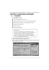
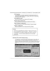
... equipped with friendly interface and solid over -clocking under windows environment. the first window you will see current CPU Speed and CPU/Memory/PCI-E/PCI Clock. TA790GX A2+/TA790GX A2+ SE/TA790GX 128M 6.2 T-SERIES SOFTWARE Installing T-Series Software 1. The drivers installation program would appear if the Auto-run function has been enabled. 2. Launching T-Series Software...
... equipped with friendly interface and solid over -clocking under windows environment. the first window you will see current CPU Speed and CPU/Memory/PCI-E/PCI Clock. TA790GX A2+/TA790GX A2+ SE/TA790GX 128M 6.2 T-SERIES SOFTWARE Installing T-Series Software 1. The drivers installation program would appear if the Auto-run function has been enabled. 2. Launching T-Series Software...

Setup Manual
Page 42
Click on "+" to increase or "-" to adjust FSB voltage. Memory Voltage This function allows user to decrease the Memory voltage. Click on "+" to increase or "-" to adjust Memory voltage. FSB Voltage This function allows user to decrease the FSB voltage. 40 Chip Voltage This function allows user to decrease the Chipset voltage. Click ...
Click on "+" to increase or "-" to adjust FSB voltage. Memory Voltage This function allows user to decrease the Memory voltage. Click on "+" to increase or "-" to adjust Memory voltage. FSB Voltage This function allows user to decrease the FSB voltage. 40 Chip Voltage This function allows user to decrease the Chipset voltage. Click ...

Setup Manual
Page 44
... block will show the information which is a convenient utility that helps you would be able to send out the mail. Provid e the name of the memory module ma nufa ct u rer. If you to enter file name. 42 Provid e the e-ma il address that you may not be collect ed in...
... block will show the information which is a convenient utility that helps you would be able to send out the mail. Provid e the name of the memory module ma nufa ct u rer. If you to enter file name. 42 Provid e the e-ma il address that you may not be collect ed in...
Setup Manual
Page 51
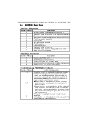
...of interference by a malfunctioning add-in flash device) POST BIOS Beep Codes Number of Beeps Description 1 Memory refresh timer error 3 Base memory read error 7 No Flash EPROM detected 10 Flash Erase error 11 Flash Program error 12 "AMIBOOT....ROM" file size error 13 BIOS ROM image mismatch (file layout does not match image present in card. z If beep codes are generated when all expansion cards except the video adapter. TA790GX A2+/TA790GX A2+ SE/TA790GX 128M...
...of interference by a malfunctioning add-in flash device) POST BIOS Beep Codes Number of Beeps Description 1 Memory refresh timer error 3 Base memory read error 7 No Flash EPROM detected 10 Flash Erase error 11 Flash Program error 12 "AMIBOOT....ROM" file size error 13 BIOS ROM image mismatch (file layout does not match image present in card. z If beep codes are generated when all expansion cards except the video adapter. TA790GX A2+/TA790GX A2+ SE/TA790GX 128M...

Setup Manual
Page 70
... 533 / 667 / 800 DDR2 1066 by AM2+ CPU) 16GB 登録済みDIMMとECC DIMM Onboard side port memory 64MB (TA790GX A2+) Radeon HD 3300 ス Onboard side port memory 128MB (TA790GX 128M 512MBです DX10/UVD/HDCP (Hybrid) CrossFireX by ATI driver) ITE 8718 Super I/O機 H/Wモニター Super...
... 533 / 667 / 800 DDR2 1066 by AM2+ CPU) 16GB 登録済みDIMMとECC DIMM Onboard side port memory 64MB (TA790GX A2+) Radeon HD 3300 ス Onboard side port memory 128MB (TA790GX 128M 512MBです DX10/UVD/HDCP (Hybrid) CrossFireX by ATI driver) ITE 8718 Super I/O機 H/Wモニター Super...


