Setup Manual
Page 2
Table of Contents Chapter 1: Introduction 1 1.1 Before You Start 1 1.2 Package Checklist 1 1.3 Motherboard Features 2 1.4 Rear Panel Connectors 4 1.5 Motherboard Layout 5 Chapter 2: Hardware Installation 6 2.1 Installing Central Processing Unit (CPU 6 2.2 FAN Headers 8 2.3 Installing System Memory 9 2.4 Connectors and Slots 11 Chapter 3: Headers & Jumpers Setup 14 3.1 How to ...
Table of Contents Chapter 1: Introduction 1 1.1 Before You Start 1 1.2 Package Checklist 1 1.3 Motherboard Features 2 1.4 Rear Panel Connectors 4 1.5 Motherboard Layout 5 Chapter 2: Hardware Installation 6 2.1 Installing Central Processing Unit (CPU 6 2.2 FAN Headers 8 2.3 Installing System Memory 9 2.4 Connectors and Slots 11 Chapter 3: Headers & Jumpers Setup 14 3.1 How to ...

Setup Manual
Page 3
...properly by area or your motherboard version. 1 Hold the board on the edge, do not try to remove the static charge. „ Avoid touching the components on motherboard or the rear side of the board unless necessary. TA790GX A2+/TA790GX A2+ SE/TA790GX 128M CHAPTER 1: INTRODUCTION 1.1 BEFORE... YOU START Thank you take the motherboard out from dangerous area, such as heat source, humid air and...
...properly by area or your motherboard version. 1 Hold the board on the edge, do not try to remove the static charge. „ Avoid touching the components on motherboard or the rear side of the board unless necessary. TA790GX A2+/TA790GX A2+ SE/TA790GX 128M CHAPTER 1: INTRODUCTION 1.1 BEFORE... YOU START Thank you take the motherboard out from dangerous area, such as heat source, humid air and...

Setup Manual
Page 4
Motherboard Manual 1.3 MOTHERBOARD FEATURES SPEC Socket AM2+ AMD 64 Architecture enables 32 and 64 bit CPU AMD Athlon 64 / Athlon 64 FX / Athlon 64 X2 computing / Sempron / Phenom ... DDR2 1066 (by AM2+ CPU) Max Memory Capicity 16GB Registered DIMM and ECC DIMM is not supported Onboard side port memory 64MB (TA790GX A2+) Onboard side port memory 128MB (TA790GX 128M) Graphics Radeon HD 3300 Max Shared Video Memory is 512MB DX10/UVD/HDCP support (Hybrid) CrossFireX support (by ATI driver) IDE AMD...
Motherboard Manual 1.3 MOTHERBOARD FEATURES SPEC Socket AM2+ AMD 64 Architecture enables 32 and 64 bit CPU AMD Athlon 64 / Athlon 64 FX / Athlon 64 X2 computing / Sempron / Phenom ... DDR2 1066 (by AM2+ CPU) Max Memory Capicity 16GB Registered DIMM and ECC DIMM is not supported Onboard side port memory 64MB (TA790GX A2+) Onboard side port memory 128MB (TA790GX 128M) Graphics Radeon HD 3300 Max Shared Video Memory is 512MB DX10/UVD/HDCP support (Hybrid) CrossFireX support (by ATI driver) IDE AMD...

Setup Manual
Page 6
Motherboard Manual 1.4 REAR PANEL CONNECTORS X PS/2 Mouse Port Y PS/2 Keyboard Port Z HDMI Port The High-Definition Multimedia Interface (HDMI) is an all-digital audio/video interface ...
Motherboard Manual 1.4 REAR PANEL CONNECTORS X PS/2 Mouse Port Y PS/2 Keyboard Port Z HDMI Port The High-Definition Multimedia Interface (HDMI) is an all-digital audio/video interface ...

Setup Manual
Page 7
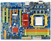
BIOS SATA1-2 JCMOS1 FDD1 JPANEL1 RSTSW1 PWRSW1 5 TA790GX A2+/TA790GX A2+ SE/TA790GX 128M 1.5 MOTHERBOARD LAYOUT JKBMS1 JATXPWR3 JCFAN1 JHDMI1 JATXPWR2 Socket AM2+ DVI VGA DIMMA1 DIMMB1 DIMMA2 DIMMB2 JUSB1 JUSBLAN1 JAUDIO2 J ATXPWR1 AMD 790GX JUSB V1 LAN JNFAN1 PEX16_2 PEX1_1 PEX1_2 BAT1 AMD SB750 SATA5-6 SATA3-4 IDE1 PEX16_1 LED_D1 LED_D2 Codec JSP DIF_ IN1 PCI1 Super I/O JAUDIOF1 JSPDIF_OUT1 JCDIN1 PCI2 JPRNT1 J COM1 JUSBV2 JUSB5 JUSB 3 JSFAN1 J USB4 Note: ■ represents the 1st pin.
BIOS SATA1-2 JCMOS1 FDD1 JPANEL1 RSTSW1 PWRSW1 5 TA790GX A2+/TA790GX A2+ SE/TA790GX 128M 1.5 MOTHERBOARD LAYOUT JKBMS1 JATXPWR3 JCFAN1 JHDMI1 JATXPWR2 Socket AM2+ DVI VGA DIMMA1 DIMMB1 DIMMA2 DIMMB2 JUSB1 JUSBLAN1 JAUDIO2 J ATXPWR1 AMD 790GX JUSB V1 LAN JNFAN1 PEX16_2 PEX1_1 PEX1_2 BAT1 AMD SB750 SATA5-6 SATA3-4 IDE1 PEX16_1 LED_D1 LED_D2 Codec JSP DIF_ IN1 PCI1 Super I/O JAUDIOF1 JSPDIF_OUT1 JCDIN1 PCI2 JPRNT1 J COM1 JUSBV2 JUSB5 JUSB 3 JSFAN1 J USB4 Note: ■ represents the 1st pin.

Setup Manual
Page 8
Motherboard Manual CHAPTER 2: HARDWARE INSTALLATION 2.1 INSTALLING CENTRAL PROCESSING UNIT (CPU) Step 1: Remove the socket protection cap. Step 3: Look for the white triangle on socket, and the gold triangle on CPU should point towards this white triangle. Step 2: Pull the lever toward direction A from the socket and then raise the lever up to a 90-degree angle. The CPU will fit only in the correct orientation. 6
Motherboard Manual CHAPTER 2: HARDWARE INSTALLATION 2.1 INSTALLING CENTRAL PROCESSING UNIT (CPU) Step 1: Remove the socket protection cap. Step 3: Look for the white triangle on socket, and the gold triangle on CPU should point towards this white triangle. Step 2: Pull the lever toward direction A from the socket and then raise the lever up to a 90-degree angle. The CPU will fit only in the correct orientation. 6

Setup Manual
Page 10
...#2, and the black wire is Ground and should be different according to the fan manufacturer. The fan cable and connector may be connected to pin#1. Motherboard Manual 2.2 FAN HEADERS These fan headers support cooling-fans built in the computer. JCFAN1: CPU Fan Header 1 4 Pin Assignment 1 Ground 2 +12V 3 FAN RPM rate sense...
...#2, and the black wire is Ground and should be different according to the fan manufacturer. The fan cable and connector may be connected to pin#1. Motherboard Manual 2.2 FAN HEADERS These fan headers support cooling-fans built in the computer. JCFAN1: CPU Fan Header 1 4 Pin Assignment 1 Ground 2 +12V 3 FAN RPM rate sense...

Setup Manual
Page 12
Dual Channel Memory installation To trigger the Dual Channel function of the motherboard, the memory module must meet the following requirements: Install memory module of the memory module must be the same (x8 or x16) 10 Dual ... O O X X Enabled X X O O Enabled O O O O (O means memory installed, X means memory not installed.) The DRAM bus width of the same density in pairs, shown in the following table. C. Motherboard Manual B. Memory Capacity DIMM Socket Location DIMMA1 DIMMB1 DIMMA2 DIMMB2 DDR2 Module 256MB/512MB/1GB/2GB/4GB 256MB/512MB/1GB/2GB/4GB 256MB/512MB/1GB...
Dual Channel Memory installation To trigger the Dual Channel function of the motherboard, the memory module must meet the following requirements: Install memory module of the memory module must be the same (x8 or x16) 10 Dual ... O O X X Enabled X X O O Enabled O O O O (O means memory installed, X means memory not installed.) The DRAM bus width of the same density in pairs, shown in the following table. C. Motherboard Manual B. Memory Capacity DIMM Socket Location DIMMA1 DIMMB1 DIMMA2 DIMMB2 DDR2 Module 256MB/512MB/1GB/2GB/4GB 256MB/512MB/1GB/2GB/4GB 256MB/512MB/1GB...
Setup Manual
Page 13
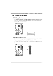
TA790GX A2+/TA790GX A2+ SE/TA790GX 128M 2.4 CONNECTORS AND SLOTS FDD1: Floppy Disk Connector The motherboard provides a standard floppy disk connector that provides PIO Mode 0~4, Bus Master, and Ultra DMA 33/66/100/133 functionality. The IDE connector can connect a master and a slave drive, so you can connect up to two drives. 40 39 2 1 11 This connector supports the provided floppy drive ribbon cables. 2 34 1 33 IDE1: IDE/ATAPI Connector The motherboard has a 32-bit Enhanced IDE Controller that supports 360K, 720K, 1.2M, 1.44M and 2.88M floppy disk types.
TA790GX A2+/TA790GX A2+ SE/TA790GX 128M 2.4 CONNECTORS AND SLOTS FDD1: Floppy Disk Connector The motherboard provides a standard floppy disk connector that provides PIO Mode 0~4, Bus Master, and Ultra DMA 33/66/100/133 functionality. The IDE connector can connect a master and a slave drive, so you can connect up to two drives. 40 39 2 1 11 This connector supports the provided floppy drive ribbon cables. 2 34 1 33 IDE1: IDE/ATAPI Connector The motherboard has a 32-bit Enhanced IDE Controller that supports 360K, 720K, 1.2M, 1.44M and 2.88M floppy disk types.
Setup Manual
Page 14
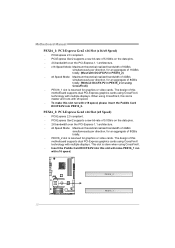
...x16 Speed Mode: Maximum theoretical realized bandwidth of 8GB/s simultaneously per direction, for an aggregate of this slot will make this motherboard supports dual PCI-Express graphics cards using CrossFireX technology with multiple displays. When using CrossFireX, this slot is slave when using ... PCI-Express Gen2 supports a raw bit-rate of this slot run with x16 speed, please insert the Paddle Card DCCFX-P2 into this motherboard supports dual PCI-Express graphics cards using CrossFireX technology with multiple displays. The design of 5.0Gb/s on the data pins. - 2X bandwidth...
...x16 Speed Mode: Maximum theoretical realized bandwidth of 8GB/s simultaneously per direction, for an aggregate of this slot will make this motherboard supports dual PCI-Express graphics cards using CrossFireX technology with multiple displays. When using CrossFireX, this slot is slave when using ... PCI-Express Gen2 supports a raw bit-rate of this slot run with x16 speed, please insert the Paddle Card DCCFX-P2 into this motherboard supports dual PCI-Express graphics cards using CrossFireX technology with multiple displays. The design of 5.0Gb/s on the data pins. - 2X bandwidth...

Setup Manual
Page 15
PCI-Express 2.0 compliant. - PCI1 PCI2 13 Data transfer bandwidth up to 500MB/s per direction; 1GB/s in total. - PCI stands for expansion cards. TA790GX A2+/TA790GX A2+ SE/TA790GX 128M PEX1_1/PEX1_2: PCI-Express Gen2 x1 Slots - PEX1_ 1 PE X1_ 2 PCI1~PCI2: Peripheral Component Interconnect Slots This motherboard is a bus standard for Peripheral Component Interconnect, and it is equipped with 2 standard PCI slots. PCI-Express Gen2 supports a raw bit-rate of 5.0Gb/s on the data pins. - 2X bandwidth over the PCI-Express 1.1 architecture. This PCI slot is designated as 32 bits.
PCI-Express 2.0 compliant. - PCI1 PCI2 13 Data transfer bandwidth up to 500MB/s per direction; 1GB/s in total. - PCI stands for expansion cards. TA790GX A2+/TA790GX A2+ SE/TA790GX 128M PEX1_1/PEX1_2: PCI-Express Gen2 x1 Slots - PEX1_ 1 PE X1_ 2 PCI1~PCI2: Peripheral Component Interconnect Slots This motherboard is a bus standard for Peripheral Component Interconnect, and it is equipped with 2 standard PCI slots. PCI-Express Gen2 supports a raw bit-rate of 5.0Gb/s on the data pins. - 2X bandwidth over the PCI-Express 1.1 architecture. This PCI slot is designated as 32 bits.

Setup Manual
Page 16
... drive 13 LED 14 Reset button 15 16 Assignment N/A N/A N/A Power LED (+) Power LED (+) Power LED (-) Power button Ground Function N/A N/A Power LED Power-on button 14 Motherboard Manual CHAPTER 3: HEADERS & JUMPERS SETUP 3.1 HOW TO SETUP JUMPERS The illustration shows how to connect the PC case's front panel switch functions.
... drive 13 LED 14 Reset button 15 16 Assignment N/A N/A N/A Power LED (+) Power LED (+) Power LED (-) Power button Ground Function N/A N/A Power LED Power-on button 14 Motherboard Manual CHAPTER 3: HEADERS & JUMPERS SETUP 3.1 HOW TO SETUP JUMPERS The illustration shows how to connect the PC case's front panel switch functions.
Setup Manual
Page 18
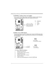
... seconds. 4. Pin Assignment 1 +12V 1 4 2 Ground 3 Ground 4 VCC JCMOS1: Clear CMOS Header By placing the jumper on the AC. 6. Set the jumper to avoid damaging the motherboard. 13 Pin 1-2 Close: Normal Operation (default). 13 13 Pin 2-3 Close: Clear CMOS data. ※ Clear CMOS Procedures: 1. Wait for the graphics card provides better graphics...
... seconds. 4. Pin Assignment 1 +12V 1 4 2 Ground 3 Ground 4 VCC JCMOS1: Clear CMOS Header By placing the jumper on the AC. 6. Set the jumper to avoid damaging the motherboard. 13 Pin 1-2 Close: Normal Operation (default). 13 13 Pin 2-3 Close: Clear CMOS data. ※ Clear CMOS Procedures: 1. Wait for the graphics card provides better graphics...

Setup Manual
Page 19
JUSB5 JUSB4 JUSB3 2 10 1 9 Pin Assignment 1 +5V (fused) 2 +5V (fused) 3 USB4 USB5 USB+ 6 USB+ 7 Ground 8 Ground 9 Key 10 NC 17 TA790GX A2+/TA790GX A2+ SE/TA790GX 128M SATA1-2/SATA3-4/SATA5-6: Serial ATA Connectors The motherboard has a PCI to connect additional USB cable on the PC front panel, and also can be connected with transfer rate of...
JUSB5 JUSB4 JUSB3 2 10 1 9 Pin Assignment 1 +5V (fused) 2 +5V (fused) 3 USB4 USB5 USB+ 6 USB+ 7 Ground 8 Ground 9 Key 10 NC 17 TA790GX A2+/TA790GX A2+ SE/TA790GX 128M SATA1-2/SATA3-4/SATA5-6: Serial ATA Connectors The motherboard has a PCI to connect additional USB cable on the PC front panel, and also can be connected with transfer rate of...

Setup Manual
Page 20
... Assignment 1 +5V 2 SPDIF_OUT 3 Ground JSPDIF_IN1: Digital Audio-in Connector This connector allows user to connect the front audio output cable with the PC front panel. Motherboard Manual JAUDIOF1: Front Panel Audio Header This header allows user to connect the PCI bracket SPDIF input header.
... Assignment 1 +5V 2 SPDIF_OUT 3 Ground JSPDIF_IN1: Digital Audio-in Connector This connector allows user to connect the front audio output cable with the PC front panel. Motherboard Manual JAUDIOF1: Front Panel Audio Header This header allows user to connect the PCI bracket SPDIF input header.

Setup Manual
Page 22
JUSBV2: +5V STB for USB ports at JUSB3/JUSB4/JUSB5. JUSBV2: +5V for USB ports at JUSB3/JUSB4/JUSB5. Motherboard Manual JCOM1: Serial port Connector The motherboard has a Serial Port Connector for connecting RS-232 Port. 2 10 Pin Assignment 1 Carrier detect 2 Received data 3 Transmitted data 4 Data terminal ready 5 Signal ground 6 Data set ...
JUSBV2: +5V STB for USB ports at JUSB3/JUSB4/JUSB5. JUSBV2: +5V for USB ports at JUSB3/JUSB4/JUSB5. Motherboard Manual JCOM1: Serial port Connector The motherboard has a Serial Port Connector for connecting RS-232 Port. 2 10 Pin Assignment 1 Carrier detect 2 Received data 3 Transmitted data 4 Data terminal ready 5 Signal ground 6 Data set ...

Setup Manual
Page 23
Please refer to show system status. RSTSW1: This is an on -board Reset button. 21 RSTSW1 PWRSW1 PWRSW1: This is an on -board Power Switch button. TA790GX A2+/TA790GX A2+ SE/TA790GX 128M On-Board LED Indicators There are 2 on-board buttons. LED_D1 LED_D2 LED_D1 and LED_D2: These 2 LED indicate system power on the motherboard to the table below for different messages: LED_D2 OFF OFF ON ON LED_D1 OFF ON OFF ON Message Abnormal: CPU / Chipset error. Memory Error VGA Error Normal On-Board Buttons There are 2 LED indicators on diagnostics.
Please refer to show system status. RSTSW1: This is an on -board Reset button. 21 RSTSW1 PWRSW1 PWRSW1: This is an on -board Power Switch button. TA790GX A2+/TA790GX A2+ SE/TA790GX 128M On-Board LED Indicators There are 2 on-board buttons. LED_D1 LED_D2 LED_D1 and LED_D2: These 2 LED indicate system power on the motherboard to the table below for different messages: LED_D2 OFF OFF ON ON LED_D1 OFF ON OFF ON Message Abnormal: CPU / Chipset error. Memory Error VGA Error Normal On-Board Buttons There are 2 LED indicators on diagnostics.
Setup Manual
Page 24
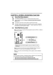
.../crossfire/tutorials.html http://ati.amd.com/technology/crossfire/howitworksdemo.html 22 Step 3: Connect the CrossFireX Bridge with Radeon HD3650/HD3850/HD3870/HD4850/ HD4870 GPU. Motherboard Manual CHAPTER 4: (HYBRID) CROSSFIREX FUNCTION 4.1 CROSSFIREX REQUIREMENTS Only Windows XP/Vista supports CrossFireX (Dual Video) function.
.../crossfire/tutorials.html http://ati.amd.com/technology/crossfire/howitworksdemo.html 22 Step 3: Connect the CrossFireX Bridge with Radeon HD3650/HD3850/HD3870/HD4850/ HD4870 GPU. Motherboard Manual CHAPTER 4: (HYBRID) CROSSFIREX FUNCTION 4.1 CROSSFIREX REQUIREMENTS Only Windows XP/Vista supports CrossFireX (Dual Video) function.

Setup Manual
Page 26
Motherboard Manual 4.5 OPERATION MODES SUPPORTING LIST Operation Mode Single Card Model Radeon HD3650 O Radeon HD3850 O Radeon HD3870 O Radeon HD4850 O Radeon HD4870 O Radeon HD3450 O Radeon HD3470 O Radeon HD3870X2 O CrossFireX Hybrid CrossFireX O X O X O X O X O X X O X O X X (O means Supported, X means Not Supported.) 24
Motherboard Manual 4.5 OPERATION MODES SUPPORTING LIST Operation Mode Single Card Model Radeon HD3650 O Radeon HD3850 O Radeon HD3870 O Radeon HD4850 O Radeon HD4870 O Radeon HD3450 O Radeon HD3470 O Radeon HD3870X2 O CrossFireX Hybrid CrossFireX O X O X O X O X O X X O X O X X (O means Supported, X means Not Supported.) 24

Setup Manual
Page 28
... other application that eliminates tedious manual backups to the other drive. Drawbacks: Requires 2 drives for high-availability solutions, or as a form of one drive. Motherboard Manual RAID 1: Every read and write is actually carried out in parallel across 2 disk drives in the array. RAID techniques can reside on the same...
... other application that eliminates tedious manual backups to the other drive. Drawbacks: Requires 2 drives for high-availability solutions, or as a form of one drive. Motherboard Manual RAID 1: Every read and write is actually carried out in parallel across 2 disk drives in the array. RAID techniques can reside on the same...

