

The Bose® Lifestyle® amplifier - Owner's guide
Page 4
... product complies with the instructions, may cause harmful interference to the antenna grounding illustration on a different circuit than the one or more of USA) that the cable ground shall be connected to the grounding system of the building, as close to the point of the receiver or radio remote control could void the user's authority to this page. This equipment generates, uses...
... product complies with the instructions, may cause harmful interference to the antenna grounding illustration on a different circuit than the one or more of USA) that the cable ground shall be connected to the grounding system of the building, as close to the point of the receiver or radio remote control could void the user's authority to this page. This equipment generates, uses...

The Bose® Lifestyle® amplifier - Owner's guide
Page 5
...bottom panel of your sales receipt and warranty card together with this owner's guide. AM262840_00_V.pdf January 4, 2002 3 Contents Setting up your Lifestyle® Stereo Amplifier Before you begin 4 Unpacking the carton 4 Selecting a location for your Lifestyle® stereo amplifier 5 Connecting the Lifestyle® stereo amplifier to a multi-room interface 7 Connecting the Lifestyle® stereo amplifier to a Lifestyle® media center 9 Setting up the remote control 10 Setting Zone 2 Protocol 10 Connecting the Lifestyle® stereo amplifier to a Model 20 music center 11...
...bottom panel of your sales receipt and warranty card together with this owner's guide. AM262840_00_V.pdf January 4, 2002 3 Contents Setting up your Lifestyle® Stereo Amplifier Before you begin 4 Unpacking the carton 4 Selecting a location for your Lifestyle® stereo amplifier 5 Connecting the Lifestyle® stereo amplifier to a multi-room interface 7 Connecting the Lifestyle® stereo amplifier to a Lifestyle® media center 9 Setting up the remote control 10 Setting Zone 2 Protocol 10 Connecting the Lifestyle® stereo amplifier to a Model 20 music center 11...
The Bose® Lifestyle® amplifier - Owner's guide
Page 6
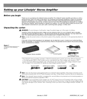
... system, you check the position of the voltage selection switch on the rear panel of the shipping carton 30-ft audio input cable PN197406 Lifestyle® stereo amplifier Owner's guide Power cord* USA/Canada (120V) * The Lifestyle® stereo amplifier includes a 120V AC (mains) power cord for use . By using the Lifestyle® stereo amplifier to see if you with Bose non-powered environmental speakers or Bose non-powered accessory speakers...
... system, you check the position of the voltage selection switch on the rear panel of the shipping carton 30-ft audio input cable PN197406 Lifestyle® stereo amplifier Owner's guide Power cord* USA/Canada (120V) * The Lifestyle® stereo amplifier includes a 120V AC (mains) power cord for use . By using the Lifestyle® stereo amplifier to see if you with Bose non-powered environmental speakers or Bose non-powered accessory speakers...

The Bose® Lifestyle® amplifier - Owner's guide
Page 9
...;er Lifestyle® stereo amplifier rear panel Multi-room interface rear panel 4 Ω MINIMUM LL R L SYSTEM RR CONTROL L R +- Setting Up Your Lifestyle® Stereo Amplifier Connecting the Lifestyle® stereo amplifier to a multi-room interface CAUTION: Before making any connections, turn the Lifestyle® system off and disconnect the music center from the AC (mains) power outlet. At the other connections. 1. Insert the white RCA piggyback connector of the supplied cable into the R (right) INPUT jack of...
...;er Lifestyle® stereo amplifier rear panel Multi-room interface rear panel 4 Ω MINIMUM LL R L SYSTEM RR CONTROL L R +- Setting Up Your Lifestyle® Stereo Amplifier Connecting the Lifestyle® stereo amplifier to a multi-room interface CAUTION: Before making any connections, turn the Lifestyle® system off and disconnect the music center from the AC (mains) power outlet. At the other connections. 1. Insert the white RCA piggyback connector of the supplied cable into the R (right) INPUT jack of...

The Bose® Lifestyle® amplifier - Owner's guide
Page 11
... the red RCA piggyback connector into an outlet until you have completed all other end of the audio input cable, insert the 3.5 mm mini-plug into the SYSTEM CONTROL jack on the rear panel of the audio input cable into the L (left) INPUT jack. Setting Up Your Lifestyle® Stereo Amplifier Connecting the Lifestyle® stereo amplifier to a Lifestyle® media center CAUTION: Before making connections, turn the Lifestyle® system off and disconnect the media center from the AC (mains) power outlet...
... the red RCA piggyback connector into an outlet until you have completed all other end of the audio input cable, insert the 3.5 mm mini-plug into the SYSTEM CONTROL jack on the rear panel of the audio input cable into the L (left) INPUT jack. Setting Up Your Lifestyle® Stereo Amplifier Connecting the Lifestyle® stereo amplifier to a Lifestyle® media center CAUTION: Before making connections, turn the Lifestyle® system off and disconnect the media center from the AC (mains) power outlet...

The Bose® Lifestyle® amplifier - Owner's guide
Page 12
... code settings (switches 1, 2, 3, and 4) match those in more ...". On Off Mute All Mute SOURCE / INPUT CD/DVD Changer FM/AM TV VCR AUX MENU / NAVIGATION Settings Tune Disc Seek Enter Channel Chapter Preset Track Volume 1 2 3 4 5 6 7 8 9 0 PLAYBACK Stop Pause Play Shuffle Repeat Settings Settings ( ) System Setup Enter System Setup (3 of 3). Note: Refer to your system in your remote control. This will now see a menu entitled System Setup (1 of 3) Zone 2 Protocol: Legacy 10 January 4, 2002 AM262840_00_V.pdf Setting Up Your Lifestyle® Stereo...
... code settings (switches 1, 2, 3, and 4) match those in more ...". On Off Mute All Mute SOURCE / INPUT CD/DVD Changer FM/AM TV VCR AUX MENU / NAVIGATION Settings Tune Disc Seek Enter Channel Chapter Preset Track Volume 1 2 3 4 5 6 7 8 9 0 PLAYBACK Stop Pause Play Shuffle Repeat Settings Settings ( ) System Setup Enter System Setup (3 of 3). Note: Refer to your system in your remote control. This will now see a menu entitled System Setup (1 of 3) Zone 2 Protocol: Legacy 10 January 4, 2002 AM262840_00_V.pdf Setting Up Your Lifestyle® Stereo...

The Bose® Lifestyle® amplifier - Owner's guide
Page 13
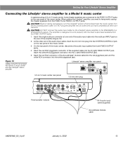
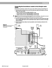
... CAUTION: Before making connections, turn the Lifestyle® system off and disconnect the music center from the AC (mains) power outlet. At the other connections. 1. Insert the white RCA piggyback connector of the supplied cable into the R (right) INPUT jack of the music center (Figure 10). 2. SPEAKER OUTPUTS INPUT Model 20 music center rear panel 30-ft audio input cable (supplied) AM262840_00_V.pdf January 4, 2002 11 DO NOT plug the amplifier into the SYSTEM CONTROL jack on the rear panel of the ampli...
... CAUTION: Before making connections, turn the Lifestyle® system off and disconnect the music center from the AC (mains) power outlet. At the other connections. 1. Insert the white RCA piggyback connector of the supplied cable into the R (right) INPUT jack of the music center (Figure 10). 2. SPEAKER OUTPUTS INPUT Model 20 music center rear panel 30-ft audio input cable (supplied) AM262840_00_V.pdf January 4, 2002 11 DO NOT plug the amplifier into the SYSTEM CONTROL jack on the rear panel of the ampli...
The Bose® Lifestyle® amplifier - Owner's guide
Page 15
... center from both FIXED OUTPUT jacks. 4. Insert the red RCA connector of the supplied cable into an outlet until you need to work properly with the fixed output level available from the FIXED R and FIXED L OUTPUT jacks. At the other connections. SPSEPAEKAEKREROOUUTPTUPUTSTS INPUT 3.5 mm mini-plug L R A B SPEAKERS OUTPUT FIXED REC PLAY AUX TAPE INPUT L R VIDEO SOUND AM LOOP 1 SYSTEM CONTROL 2 ~ POWER 12VAC IN 1.0A ANTENNA SEE INSTRUCTION MANUAL Fixed speaker outputs 30-ft audio input cable (supplied) Acoustimass module cable AM262840_00_V.pdf...
... center from both FIXED OUTPUT jacks. 4. Insert the red RCA connector of the supplied cable into an outlet until you need to work properly with the fixed output level available from the FIXED R and FIXED L OUTPUT jacks. At the other connections. SPSEPAEKAEKREROOUUTPTUPUTSTS INPUT 3.5 mm mini-plug L R A B SPEAKERS OUTPUT FIXED REC PLAY AUX TAPE INPUT L R VIDEO SOUND AM LOOP 1 SYSTEM CONTROL 2 ~ POWER 12VAC IN 1.0A ANTENNA SEE INSTRUCTION MANUAL Fixed speaker outputs 30-ft audio input cable (supplied) Acoustimass module cable AM262840_00_V.pdf...
The Bose® Lifestyle® amplifier - Owner's guide
Page 18
... the audio input cable.) • Disconnect any solvents, chemicals, or cleaning solutions containing alcohol, ammonia, or abrasives. Protecting outdoor wiring Although some Bose® speakers are firmly connected at hardware stores. Do not use any headphones. • Make sure the remote control switch settings are connected and the knobs tightened down. If CD or AUX is plugged into the FIXED OUTPUTs on the music center. (Then the speaker output cable to the Acoustimass® module...
... the audio input cable.) • Disconnect any solvents, chemicals, or cleaning solutions containing alcohol, ammonia, or abrasives. Protecting outdoor wiring Although some Bose® speakers are firmly connected at hardware stores. Do not use any headphones. • Make sure the remote control switch settings are connected and the knobs tightened down. If CD or AUX is plugged into the FIXED OUTPUTs on the music center. (Then the speaker output cable to the Acoustimass® module...

The Bose® Lifestyle® amplifier - Owner's guide
Page 19
... amplifier rear panel. If the speaker now plays, continue checking for correct phone numbers. Make sure the wires are using a Lifestyle® DVD system, the stereo amplifier will not work unless work at the other outputs on page 14. to -. • See "Connecting speakers to your listening area. Remote does not adjust the volume • Be sure the 1/8" mini-plug is firmly inserted in the system settings menu is in that...
... amplifier rear panel. If the speaker now plays, continue checking for correct phone numbers. Make sure the wires are using a Lifestyle® DVD system, the stereo amplifier will not work unless work at the other outputs on page 14. to -. • See "Connecting speakers to your listening area. Remote does not adjust the volume • Be sure the 1/8" mini-plug is firmly inserted in the system settings menu is in that...

Owner's guide
Page 4
... the NEC (of USA) that the cable ground shall be connected to the grounding system of the building, as marked on this product, be fatal. Do not install external antennas near overhead power lines or other electric light or power circuits, nor where an antenna can fall into a proper power source, as described in the operating instructions or as close to grounding electrodes, and...
... the NEC (of USA) that the cable ground shall be connected to the grounding system of the building, as marked on this product, be fatal. Do not install external antennas near overhead power lines or other electric light or power circuits, nor where an antenna can fall into a proper power source, as described in the operating instructions or as close to grounding electrodes, and...
Owner's guide
Page 5
... Acoustimass® module. Setting Up Before you keep your records Serial numbers are located on the music center 13 Operating Your Lifestyle® 5 music system The music center display 14 The system controls ...14 The music center controls 15 The Lifestyle® remote control 15 Listening to the radio 16 Listening to find... Contents Where to a CD ...17 Using the system with an external component 17 Maintaining Your Lifestyle® 5 music system Fine-tuning your system 18 Changing the house code settings 19 Adding speakers ...20 Troubleshooting...
... Acoustimass® module. Setting Up Before you keep your records Serial numbers are located on the music center 13 Operating Your Lifestyle® 5 music system The music center display 14 The system controls ...14 The music center controls 15 The Lifestyle® remote control 15 Listening to the radio 16 Listening to find... Contents Where to a CD ...17 Using the system with an external component 17 Maintaining Your Lifestyle® 5 music system Fine-tuning your system 18 Changing the house code settings 19 Adding speakers ...20 Troubleshooting...

Owner's guide
Page 9
... Acoustimass module (the length of your dealer or call Bose®. 3. Allow enough room to avoid blocking the port or creating too much bass. 7. Place the module along the wall to open the CD player cover. 2. under a table, behind a sofa. Select a position for the built-in Figure 3. ® Preferred ® position Treble Bass Alternate position ® AUDIO INPUT OUTPUTS TO CUBE SPEAKERS RIGHT LEFT OFF POWER...
... Acoustimass module (the length of your dealer or call Bose®. 3. Allow enough room to avoid blocking the port or creating too much bass. 7. Place the module along the wall to open the CD player cover. 2. under a table, behind a sofa. Select a position for the built-in Figure 3. ® Preferred ® position Treble Bass Alternate position ® AUDIO INPUT OUTPUTS TO CUBE SPEAKERS RIGHT LEFT OFF POWER...
Owner's guide
Page 11
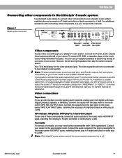
... center Connect the Acoustimass module to the music center with the audio input cable (Figure 5). 1. If the black connector is not inserted fully into SYSTEM CONTROL 1 ® LIFESTYLE ® MODEL 5 MUSIC CENTER B Z G642 950 D S T BOSE Corporation UL LISTED 917D AUDIO ® EQUIPMENT MANUFACTURED: TÜV Rheinland BOSE CORPORATION, FRAMINGHAM, MA 01701-9168 MADE IN USA geprüdfte Sicherheit SPEAKERS L FIXED R 93 A B OUTPUT TAPE AUX VIDEO SOUND L R REC PLAY INPUT AM LOOP ANTENNA SYSTEM CONTROL 1 ~ POWER 12VAC IN 1.0A 2 AC power jack AM191413_02_V.pdf...
... center Connect the Acoustimass module to the music center with the audio input cable (Figure 5). 1. If the black connector is not inserted fully into SYSTEM CONTROL 1 ® LIFESTYLE ® MODEL 5 MUSIC CENTER B Z G642 950 D S T BOSE Corporation UL LISTED 917D AUDIO ® EQUIPMENT MANUFACTURED: TÜV Rheinland BOSE CORPORATION, FRAMINGHAM, MA 01701-9168 MADE IN USA geprüdfte Sicherheit SPEAKERS L FIXED R 93 A B OUTPUT TAPE AUX VIDEO SOUND L R REC PLAY INPUT AM LOOP ANTENNA SYSTEM CONTROL 1 ~ POWER 12VAC IN 1.0A 2 AC power jack AM191413_02_V.pdf...
Owner's guide
Page 13
... SPEAKERS L FIXED R 93 A B OUTPUT TAPE AUX VIDEO SOUND L R REC PLAY INPUT AM LOOP ANTENNA SYSTEM CONTROL 1 POWER ~ 12VAC IN 1.0A 2 Tape input Auxiliary Video sound jacks input jacks input jacks Video components To play the same monaural sound. However, the left ). Note: To ensure proper stereo sound, connect the L and R audio outputs from the tape deck to the music center TAPE PLAY INPUT jacks, matching the red plug to R (right) and black or white plug to L (left ). AM191413_02_V.pdf December 20, 2001 11 Other connections Tape deck To use the TV remote...
... SPEAKERS L FIXED R 93 A B OUTPUT TAPE AUX VIDEO SOUND L R REC PLAY INPUT AM LOOP ANTENNA SYSTEM CONTROL 1 POWER ~ 12VAC IN 1.0A 2 Tape input Auxiliary Video sound jacks input jacks input jacks Video components To play the same monaural sound. However, the left ). Note: To ensure proper stereo sound, connect the L and R audio outputs from the tape deck to the music center TAPE PLAY INPUT jacks, matching the red plug to R (right) and black or white plug to L (left ). AM191413_02_V.pdf December 20, 2001 11 Other connections Tape deck To use the TV remote...

Owner's guide
Page 14
... 9 The antenna connections FM antenna AM antenna jack terminals ® LIFESTYLE ® MODEL 5 MUSIC CENTER B Z G642 950 D S T BOSE Corporation UL LISTED 917D AUDIO ® EQUIPMENT MANUFACTURED: TÜV Rheinland BOSE CORPORATION, FRAMINGHAM, MA 01701-9168 MADE IN USA geprüdfte Sicherheit SPEAKERS L FIXED R 93 A B OUTPUT TAPE AUX VIDEO SOUND L R REC PLAY INPUT AM LOOP ANTENNA SYSTEM CONTROL 1 ~ POWER 12VAC IN 1.0A 2 Figure 10 The FM dipole antenna Figure 11 The AM loop antenna FM antenna connections 1. Plug the antenna connector into matching...
... 9 The antenna connections FM antenna AM antenna jack terminals ® LIFESTYLE ® MODEL 5 MUSIC CENTER B Z G642 950 D S T BOSE Corporation UL LISTED 917D AUDIO ® EQUIPMENT MANUFACTURED: TÜV Rheinland BOSE CORPORATION, FRAMINGHAM, MA 01701-9168 MADE IN USA geprüdfte Sicherheit SPEAKERS L FIXED R 93 A B OUTPUT TAPE AUX VIDEO SOUND L R REC PLAY INPUT AM LOOP ANTENNA SYSTEM CONTROL 1 ~ POWER 12VAC IN 1.0A 2 Figure 10 The FM dipole antenna Figure 11 The AM loop antenna FM antenna connections 1. Plug the antenna connector into matching...

Owner's guide
Page 15
... (I) position. Setting Up Set up the remote control Install the batteries 1. Slide open the battery compartment on the module connection panel to the following pages for information on page 15.) The display indicates US for North American spacing and EU for a few days, you complete all cable and power connections before turning on the batteries with other Lifestyle® music systems. Figure 13 Installing the remote control batteries 3 AA batteries Battery compartment cover Miniature switches Set radio channel spacing for...
... (I) position. Setting Up Set up the remote control Install the batteries 1. Slide open the battery compartment on the module connection panel to the following pages for information on page 15.) The display indicates US for North American spacing and EU for a few days, you complete all cable and power connections before turning on the batteries with other Lifestyle® music systems. Figure 13 Installing the remote control batteries 3 AA batteries Battery compartment cover Miniature switches Set radio channel spacing for...

Owner's guide
Page 16
... /PRESET SEEK VOLUME Music Center AUTO OFF - OFF MUTE - Silences the speakers. Operating Your Lifestyle® 5 music system The music center display This music center display (Figure 14) provides information on , switches between AM and FM. Figure 14 The music center display CD track and AM/FM preset number display Source indicators CD elapsed time and AM/FM station frequency display CD AM FM VIDEO STEREO TAPE DISC TRACK AUX RANDOM PRESET AUTO OFFMUTE Play indicator Pause indicator No disc indicator The system controls Function AUX - VIDEO - TAPE - AM/FM - When the radio...
... /PRESET SEEK VOLUME Music Center AUTO OFF - OFF MUTE - Silences the speakers. Operating Your Lifestyle® 5 music system The music center display This music center display (Figure 14) provides information on , switches between AM and FM. Figure 14 The music center display CD track and AM/FM preset number display Source indicators CD elapsed time and AM/FM station frequency display CD AM FM VIDEO STEREO TAPE DISC TRACK AUX RANDOM PRESET AUTO OFFMUTE Play indicator Pause indicator No disc indicator The system controls Function AUX - VIDEO - TAPE - AM/FM - When the radio...

Owner's guide
Page 19
... its remote control. Connecting headphones automatically shuts off . Using the CD player The following operations apply to keys on both the remote control and the music center, except where noted: • To play a stopped or paused CD, press PLAY/PAUSE. • To pause a CD, press . • To stop a CD, hold SKIP or SKIP . • To play . Set the tape unit to SPEAKERS A and FIXED OUTPUTs. Using the system with an external component Follow the instructions for...
... its remote control. Connecting headphones automatically shuts off . Using the CD player The following operations apply to keys on both the remote control and the music center, except where noted: • To play a stopped or paused CD, press PLAY/PAUSE. • To pause a CD, press . • To stop a CD, hold SKIP or SKIP . • To play . Set the tape unit to SPEAKERS A and FIXED OUTPUTs. Using the system with an external component Follow the instructions for...

Owner's guide
Page 23
... the music center. • Make sure the remote control house code matches the music center code. Clean the CD. Follow steps 4-7 on again, to the component owner's manual. This allows the unit to reset itself after a power surge or power interruption. • Make sure the audio input cable is connected to the music center SPEAKERS A outputs, the black connector is fully seated in the music center SYSTEM CONTROL 1 jack, and the multi-pin connector is firmly seated in the Acoustimass module jack. • Make sure the module power switch...
... the music center. • Make sure the remote control house code matches the music center code. Clean the CD. Follow steps 4-7 on again, to the component owner's manual. This allows the unit to reset itself after a power surge or power interruption. • Make sure the audio input cable is connected to the music center SPEAKERS A outputs, the black connector is fully seated in the music center SYSTEM CONTROL 1 jack, and the multi-pin connector is firmly seated in the Acoustimass module jack. • Make sure the module power switch...


