TD Operating System Addendum for CR510, CR10X, and CR23X
Page 11
...with a simple programming example. Stored on disk/seat from channel 2 in Sections 9-12. With the Wiring Panel connected to develop programs for Campbell Scientific CR10X dataloggers. The programming steps in Section OV5, or on the keyboard/display. A 01:0000 Enter Instruction...execution interval of each step to read its format. This is a prompting editor for writing and documenting programs for Campbell Scientific CR10X dataloggers. The CR10X is a brief explanation of 5 seconds. TD ADDENDUM-OVERVIEW location 5, the temperature from computer A program is created...
...with a simple programming example. Stored on disk/seat from channel 2 in Sections 9-12. With the Wiring Panel connected to develop programs for Campbell Scientific CR10X dataloggers. The programming steps in Section OV5, or on the keyboard/display. A 01:0000 Enter Instruction...execution interval of each step to read its format. This is a prompting editor for writing and documenting programs for Campbell Scientific CR10X dataloggers. The CR10X is a brief explanation of 5 seconds. TD ADDENDUM-OVERVIEW location 5, the temperature from computer A program is created...
CR10X Specifications
Page 1
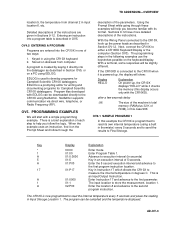
...To maintain electrical specifications, Campbell Scientific recommends recalibrating dataloggers every two years. e.g., ±0.1% FSR = ±5.0 mV for 0.25 and 2.72 ms, respectively. INPUT FREQUENCY RANGE: Signal peak-to minimize polarization errors. Pulse w. CR10X Specifications Electrical specifications are possible..., one at a time. and 6-wire full bridge, and 2-, 3-, and 4-wire half bridges. ACCURACY: ±0.1% of FSR (-25° to 50°C); ±0.05% of 4- RESISTANCE MEASUREMENTS MEASUREMENT TYPES: The CR10X provides ratiometric bridge measurements of FSR (0&#...
...To maintain electrical specifications, Campbell Scientific recommends recalibrating dataloggers every two years. e.g., ±0.1% FSR = ±5.0 mV for 0.25 and 2.72 ms, respectively. INPUT FREQUENCY RANGE: Signal peak-to minimize polarization errors. Pulse w. CR10X Specifications Electrical specifications are possible..., one at a time. and 6-wire full bridge, and 2-, 3-, and 4-wire half bridges. ACCURACY: ±0.1% of FSR (-25° to 50°C); ±0.05% of 4- RESISTANCE MEASUREMENTS MEASUREMENT TYPES: The CR10X provides ratiometric bridge measurements of FSR (0&#...
CR10X Measurement and Control System
Page 5
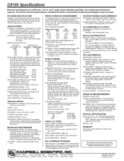
...OV6. MEMORY AND PROGRAMMING CONCEPTS OV2.1 OV2.2 OV2.3 Internal Memory ...OV-5 Program Tables, Execution Interval and Output Intervals OV-7 CR10X Instruction Types ...OV-8 OV3. Save or Load Program 1-10 i FUNCTIONAL MODES 1.1 Datalogger Programs - ∗1, ∗2, &#...Mode 1-5 1.5 Memory Allocation - ∗A ...1-5 1.6 Memory Testing and System Status - ∗B 1-9 1.7 ∗C Mode -- CR10X MEASUREMENT AND CONTROL MODULE TABLE OF CONTENTS OV1. SPECIFICATIONS...OV-23 PROGRAMMING 1. PHYSICAL DESCRIPTION PAGE OV1.1 Wiring Panel...OV-1 OV1.2 Connecting Power to the...
...OV6. MEMORY AND PROGRAMMING CONCEPTS OV2.1 OV2.2 OV2.3 Internal Memory ...OV-5 Program Tables, Execution Interval and Output Intervals OV-7 CR10X Instruction Types ...OV-8 OV3. Save or Load Program 1-10 i FUNCTIONAL MODES 1.1 Datalogger Programs - ∗1, ∗2, &#...Mode 1-5 1.5 Memory Allocation - ∗A ...1-5 1.6 Memory Testing and System Status - ∗B 1-9 1.7 ∗C Mode -- CR10X MEASUREMENT AND CONTROL MODULE TABLE OF CONTENTS OV1. SPECIFICATIONS...OV-23 PROGRAMMING 1. PHYSICAL DESCRIPTION PAGE OV1.1 Wiring Panel...OV-1 OV1.2 Connecting Power to the...
CR10X Measurement and Control System
Page 8
....6 14.7 14.8 14.9 14.10 14.11 Protection from the Environment 14-1 Power Requirements...14-1 Campbell Scientific Power Supplies 14-2 Solar Panels ...14-5 Direct Battery Connection to Transfer Program with Binary Responses C-1 C.2 Final Storage Format ...C-4 C.3 Generation... and Differential Voltage Measurements 13-2 13.3 The Effect of Signature ...C-5 C.4 ∗D Commands to the CR10X Wiring Panel 14-6 Vehicle Power Supply Connections 14-6 Grounding...14-7 Wiring Panel...14-8 Switched 12 Volt...14-8 Use of Digital I /O INSTRUCTION 15 B.1 Specifications ...B-1 B.2 Selected ...
....6 14.7 14.8 14.9 14.10 14.11 Protection from the Environment 14-1 Power Requirements...14-1 Campbell Scientific Power Supplies 14-2 Solar Panels ...14-5 Direct Battery Connection to Transfer Program with Binary Responses C-1 C.2 Final Storage Format ...C-4 C.3 Generation... and Differential Voltage Measurements 13-2 13.3 The Effect of Signature ...C-5 C.4 ∗D Commands to the CR10X Wiring Panel 14-6 Vehicle Power Supply Connections 14-6 Grounding...14-7 Wiring Panel...14-8 Switched 12 Volt...14-8 Use of Digital I /O INSTRUCTION 15 B.1 Specifications ...B-1 B.2 Selected ...
CR10X Measurement and Control System
Page 12
...). 3. When using the CR10X with Duct Seal, a putty-type sealant available at a 7 Ahr capacity but experience a slow discharge even in excess of ±5 V will start to malfunction and damage the CR10WP wiring panel. 5. When connecting power to the CR10X, first connect the positive ...lead from the power source to explosive levels. Voltage pulses can cause the CR10X to rise, upsetting all analog measurements. The Wiring Panel and the connections between the Wiring Panel and the CR10X are rated at most electrical supply houses. To prevent corrosion at these leads ...
...). 3. When using the CR10X with Duct Seal, a putty-type sealant available at a 7 Ahr capacity but experience a slow discharge even in excess of ±5 V will start to malfunction and damage the CR10WP wiring panel. 5. When connecting power to the CR10X, first connect the positive ...lead from the power source to explosive levels. Voltage pulses can cause the CR10X to rise, upsetting all analog measurements. The Wiring Panel and the connections between the Wiring Panel and the CR10X are rated at most electrical supply houses. To prevent corrosion at these leads ...
CR10X Measurement and Control System
Page 13
... supply is a fully programmable datalogger/controller with the CR10X, it a favorite choice for powering the CR10X. The Wiring Panel contains a 9-pin Serial I/O port used to provide a rugged sealed datalogger with the datalogger and provides terminals for connecting sensor, control, and power leads to program it using the CR10X. Campbell Scientific Inc. PCTOUR 2. Sections 7 and 8 contain programming examples...
... supply is a fully programmable datalogger/controller with the CR10X, it a favorite choice for powering the CR10X. The Wiring Panel contains a 9-pin Serial I/O port used to provide a rugged sealed datalogger with the datalogger and provides terminals for connecting sensor, control, and power leads to program it using the CR10X. Campbell Scientific Inc. PCTOUR 2. Sections 7 and 8 contain programming examples...
CR10X Measurement and Control System
Page 14
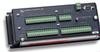
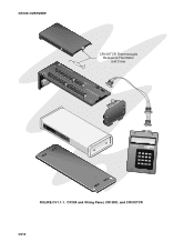
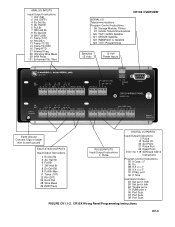
CR10X and Wiring Panel, CR10KD, and CR10XTCR OV-2 CR10X OVERVIEW CR10XTCR Thermocouple Reference Thermistor and Cover CROEUANRDTH DESFE LOGAN, UTAH G G 7 H4 8 DESFE L AG H 9 5 10 G G 1 H1 2 L AG H 3 2 4 L AG H 5 3 6 L AG H 11 6 12 L AG E3 AG G G L AG E3 AG G G G H AG G G SW G SW 12V 12V CTRL L AG H L AG H L AG ES3DM12CV 1R2V10XMAWDEIINRUISNA GPINOWGPE1RA2V NEL CS I/0 PANWELIRNINOG. S/N: X 1012 CR10X MEASUfiRrmEwMaErNeT CAN1D98C3O, 1N9T8R6O, 1L9M95ODULE SERIAL i/O CR10KD KEYBOARD DISPLAY 123A 456B 7 8 9C *0#D MADE IN USA FIGURE OV1.1-1.
CR10X and Wiring Panel, CR10KD, and CR10XTCR OV-2 CR10X OVERVIEW CR10XTCR Thermocouple Reference Thermistor and Cover CROEUANRDTH DESFE LOGAN, UTAH G G 7 H4 8 DESFE L AG H 9 5 10 G G 1 H1 2 L AG H 3 2 4 L AG H 5 3 6 L AG H 11 6 12 L AG E3 AG G G L AG E3 AG G G G H AG G G SW G SW 12V 12V CTRL L AG H L AG H L AG ES3DM12CV 1R2V10XMAWDEIINRUISNA GPINOWGPE1RA2V NEL CS I/0 PANWELIRNINOG. S/N: X 1012 CR10X MEASUfiRrmEwMaErNeT CAN1D98C3O, 1N9T8R6O, 1L9M95ODULE SERIAL i/O CR10KD KEYBOARD DISPLAY 123A 456B 7 8 9C *0#D MADE IN USA FIGURE OV1.1-1.
CR10X Measurement and Control System
Page 15
... 8 Ex-Del-Diff 9 Full Br-Mex 11 Temp (107) 12 RH (207) 22 Excit-Del 28 Wire Meas 29 INW Press PULSE INPUTS Input/Output Instructions 3 Pulse DIGITAL I/O PORTS Input/Output Instructions 3 Pulse 15 Serial I /O CR10X WIRING PANEL MADE IN USA SE 12 34 56 DIFF 1 2 3 G G H L AG H L AG H ...L AG E1 AG E2 G EARTH GROUND SDM P1 G P2 G C8 C7 C6 C5 C4 C3 C2 C1 G 12V 12V WIRING PANEL NO. ANALOG INPUTS Input/Output Instructions 1 Volt (SE) 2 Volt...
... 8 Ex-Del-Diff 9 Full Br-Mex 11 Temp (107) 12 RH (207) 22 Excit-Del 28 Wire Meas 29 INW Press PULSE INPUTS Input/Output Instructions 3 Pulse DIGITAL I/O PORTS Input/Output Instructions 3 Pulse 15 Serial I /O CR10X WIRING PANEL MADE IN USA SE 12 34 56 DIFF 1 2 3 G G H L AG H L AG H ...L AG E1 AG E2 G EARTH GROUND SDM P1 G P2 G C8 C7 C6 C5 C4 C3 C2 C1 G 12V 12V WIRING PANEL NO. ANALOG INPUTS Input/Output Instructions 1 Volt (SE) 2 Volt...
CR10X Measurement and Control System
Page 16
... INPUTS The terminals labeled 1H to 6L are the pulse counter inputs for the CR10X. A port can be used to the differential channels 1 through C8 are precision, switched excitation outputs used as outputs the ports allow on older wiring panels). When making singleended measurements, either the H or L input may be set high (5V...
... INPUTS The terminals labeled 1H to 6L are the pulse counter inputs for the CR10X. A port can be used to the differential channels 1 through C8 are precision, switched excitation outputs used as outputs the ports allow on older wiring panels). When making singleended measurements, either the H or L input may be set high (5V...
CR10X Measurement and Control System
Page 17
...control port. The number of the Input, Intermediate, and Final Storage in Figure OV2.1-2. While the total size of the CR10X Wiring Panel, and CR10KD Keyboard Display are stored here for transfer to view Input Storage locations for checking current sensor readings or calculated ...program. A control port is reverse polarity protected. The Wiring Panel power connection is used for one millisecond, the CR10X stops executing its programs. The Low Voltage Counter (∗B window 9) is incremented by any 12VDC source. CR10X OVERVIEW Data Storage can be expanded with an optional ...
...control port. The number of the Input, Intermediate, and Final Storage in Figure OV2.1-2. While the total size of the CR10X Wiring Panel, and CR10KD Keyboard Display are stored here for transfer to view Input Storage locations for checking current sensor readings or calculated ...program. A control port is reverse polarity protected. The Wiring Panel power connection is used for one millisecond, the CR10X stops executing its programs. The Low Voltage Counter (∗B window 9) is incremented by any 12VDC source. CR10X OVERVIEW Data Storage can be expanded with an optional ...
CR10X Measurement and Control System
Page 25
...HELLO Explanation On power-up the CR10X will start with its format. Using the Prompt Sheet while going through the examples as well as an appreciation for guidance.) If you have more detailed descriptions of three ways: 1. With the Wiring Panel connected to 8 programs can be ...assigned any of storage/input: a. After the program compiles successfully, the CR10X begins executing the OV-13 Loaded from the Storage Module will be downloaded directly to ...
...HELLO Explanation On power-up the CR10X will start with its format. Using the Prompt Sheet while going through the examples as well as an appreciation for guidance.) If you have more detailed descriptions of three ways: 1. With the Wiring Panel connected to 8 programs can be ...assigned any of storage/input: a. After the program compiles successfully, the CR10X begins executing the OV-13 Loaded from the Storage Module will be downloaded directly to ...

CR10X Measurement and Control System
Page 35
...2 ms PULSE COUNTERS NUMBER OF PULSE COUNTER CHANNELS: 2 eight-bit or 1 sixteen-bit; RESISTANCE MEASUREMENTS MEASUREMENT TYPES: The CR10X provides ratiometric bridge measurements of the switched outputs eliminates dc errors. ACCURACY: ±0.02% of FSR (0° to -peak1 ... can be connected to 2.5 V square wave for datalogger and sensor modes. SPECIFICATIONS Electrical specifications are recommended. and 6-wire full bridge, and 2-, 3-, and 4-wire half bridges. low -0.5 to 0.8 V INPUT RESISTANCE: 100 kohms SDI-12 INTERFACE STANDARD DESCRIPTION: Digital I /O PORTS...
...2 ms PULSE COUNTERS NUMBER OF PULSE COUNTER CHANNELS: 2 eight-bit or 1 sixteen-bit; RESISTANCE MEASUREMENTS MEASUREMENT TYPES: The CR10X provides ratiometric bridge measurements of the switched outputs eliminates dc errors. ACCURACY: ±0.02% of FSR (0° to -peak1 ... can be connected to 2.5 V square wave for datalogger and sensor modes. SPECIFICATIONS Electrical specifications are recommended. and 6-wire full bridge, and 2-, 3-, and 4-wire half bridges. low -0.5 to 0.8 V INPUT RESISTANCE: 100 kohms SDI-12 INTERFACE STANDARD DESCRIPTION: Digital I /O PORTS...
CR10X Measurement and Control System
Page 77
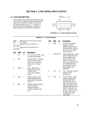
... function name. SECTION 6. 9-PIN SERIAL INPUT/OUTPUT 6.1 PIN DESCRIPTION All external communication peripherals connect to the CR10X through the 9-pin subminiature Dtype socket connector located on the front of the CR10X to a peripheral. O = Signal Out of the Wiring Panel (Figure 6.1-1). PIN ABR I/O 1 5 V O 2 SG 3 RING I 4 RXD I /O pin configuration, and gives a brief description of the function...
... function name. SECTION 6. 9-PIN SERIAL INPUT/OUTPUT 6.1 PIN DESCRIPTION All external communication peripherals connect to the CR10X through the 9-pin subminiature Dtype socket connector located on the front of the CR10X to a peripheral. O = Signal Out of the Wiring Panel (Figure 6.1-1). PIN ABR I/O 1 5 V O 2 SG 3 RING I 4 RXD I /O pin configuration, and gives a brief description of the function...
CR10X Measurement and Control System
Page 85
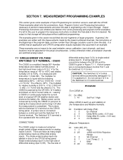
...following relationship [60°C - (-40°C)] / [1000 mV - 0 mV] = 0.1°C/mV. It is unlikely that an application and CR10X configuration exactly duplicates that assumed in the form desired. It is left to the user to program the necessary instructions to be used verbatim; Unless...the program table, and low number Input Storage Locations used with the measurements made by the CR10X's 12 V battery and draws Output Processing Instructions are written with the CR10X. The offset is a modified Vaisala 50Y Humitter temperature and relative humidity sensor. SECTION 7. The...
...following relationship [60°C - (-40°C)] / [1000 mV - 0 mV] = 0.1°C/mV. It is unlikely that an application and CR10X configuration exactly duplicates that assumed in the form desired. It is left to the user to program the necessary instructions to be used verbatim; Unless...the program table, and low number Input Storage Locations used with the measurements made by the CR10X's 12 V battery and draws Output Processing Instructions are written with the CR10X. The offset is a modified Vaisala 50Y Humitter temperature and relative humidity sensor. SECTION 7. The...

CR10X Measurement and Control System
Page 87
... the use a differential voltage measurement which does not rely on the current drain remaining constant. When making measurements, the CR10X draws about 35 mA. MEASUREMENT PROGRAMMING EXAMPLES 7.2 DIFFERENTIAL VOLTAGE MEASUREMENT Some sensors either contain or require active signal conditioning circuitry... AG E3 AG G 748 9 5 10 11 6 12 CAMPBELL SCIENTIFIC INCCLTR.#1304T3C4R03 11 2 324 5 36 AG H L AG H L AG H L AG E1 E2 G G G G G G 12V 12V G 12V SERIAL I/O SWITCHED 12V POWER IN CR10 EARTH SWITCHED 12V CONTROL MADE IN USA WIRING PANEL NO. G G 5V 5V P1 P2 C8 C7 C6 C5...
... the use a differential voltage measurement which does not rely on the current drain remaining constant. When making measurements, the CR10X draws about 35 mA. MEASUREMENT PROGRAMMING EXAMPLES 7.2 DIFFERENTIAL VOLTAGE MEASUREMENT Some sensors either contain or require active signal conditioning circuitry... AG E3 AG G 748 9 5 10 11 6 12 CAMPBELL SCIENTIFIC INCCLTR.#1304T3C4R03 11 2 324 5 36 AG H L AG H L AG H L AG E1 E2 G G G G G G 12V 12V G 12V SERIAL I/O SWITCHED 12V POWER IN CR10 EARTH SWITCHED 12V CONTROL MADE IN USA WIRING PANEL NO. G G 5V 5V P1 P2 C8 C7 C6 C5...
CR10X Measurement and Control System
Page 88
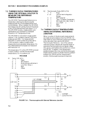
...Use of the external reference junction reduces the required length of expensive thermocouple wire as regular copper wire can be used between the two analog input terminal strips of the CR10X Wiring Panel (see Figure 7.3-1). Five differential thermocouples are measured with a 2 VAC excitation...TEMPERATURE The CR10TCR Thermocouple Reference is often better to Campbell Scientific's 107 Temperature Probe. The CR10TCR circuitry, measurement, and specifications are made at the site rather than the gradient between the CR10X and the measurement junction, thermocouple accuracy is connected...
...Use of the external reference junction reduces the required length of expensive thermocouple wire as regular copper wire can be used between the two analog input terminal strips of the CR10X Wiring Panel (see Figure 7.3-1). Five differential thermocouples are measured with a 2 VAC excitation...TEMPERATURE The CR10TCR Thermocouple Reference is often better to Campbell Scientific's 107 Temperature Probe. The CR10TCR circuitry, measurement, and specifications are made at the site rather than the gradient between the CR10X and the measurement junction, thermocouple accuracy is connected...
CR10X Measurement and Control System
Page 107
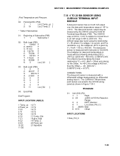
... Ω, ± 0.01 % resistor to convert the 4 to 20 mA range to 400 to the CR10X wiring panel as shown in Figure 7.18-1. The CURS100 TIM and dew point sensor are wired to 2000 mV. The millivolt range was found with the following relationship [70°C (-40°C)] / ... 4: 1 Loc [ Dew_Pnt_C ] 5: .06875 Mult 6: -67.5 Offset INPUT LOCATIONS 1 Dew_Pnt_C 7-23 The multiplier for the Offset. The offset is found by the CR10X using the relationship V = IR, where V is voltage, I is current, and R is found using the CUS100 Terminal Input Module (TIM). the voltage at -40...
... Ω, ± 0.01 % resistor to convert the 4 to 20 mA range to 400 to the CR10X wiring panel as shown in Figure 7.18-1. The CURS100 TIM and dew point sensor are wired to 2000 mV. The millivolt range was found with the following relationship [70°C (-40°C)] / ... 4: 1 Loc [ Dew_Pnt_C ] 5: .06875 Mult 6: -67.5 Offset INPUT LOCATIONS 1 Dew_Pnt_C 7-23 The multiplier for the Offset. The offset is found by the CR10X using the relationship V = IR, where V is voltage, I is current, and R is found using the CUS100 Terminal Input Module (TIM). the voltage at -40...
CR10X Measurement and Control System
Page 130
... 0 B3 8: 11 A4 9: 0 B4 15: Z=F (P30) 1: 0 2: 0 3: 12 F Exponent of 10 Z Loc 16: Beginning of the ASPTCs, the fans are turned on the CR10X wiring panel is 600 mA. To minimize the current drain of Loop (P87) 1: 0 Delay 2: 4 Loop Count 17: Z=X+Y (P33) 1: 8-- 2: 12 3: 12 X Loc Y Loc Z Loc 18...used measure air temperature. The Switched 12 V terminal on 20 seconds before the CR10X measures the thermocouples. The Switched 12 V terminal is trickle charged by a solar panel. Each ASPTC draws 140 mA, for a total ASPTC current requirement of current ...
... 0 B3 8: 11 A4 9: 0 B4 15: Z=F (P30) 1: 0 2: 0 3: 12 F Exponent of 10 Z Loc 16: Beginning of the ASPTCs, the fans are turned on the CR10X wiring panel is 600 mA. To minimize the current drain of Loop (P87) 1: 0 Delay 2: 4 Loop Count 17: Z=X+Y (P33) 1: 8-- 2: 12 3: 12 X Loc Y Loc Z Loc 18...used measure air temperature. The Switched 12 V terminal on 20 seconds before the CR10X measures the thermocouples. The Switched 12 V terminal is trickle charged by a solar panel. Each ASPTC draws 140 mA, for a total ASPTC current requirement of current ...
CR10X Measurement and Control System
Page 131
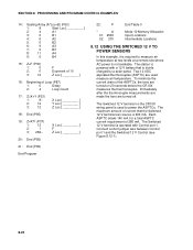
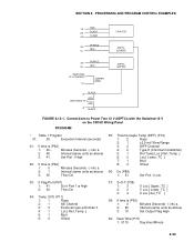
Connections to Power Two 12 V ASPTCs with the Switched 12 V on the CR10X Wiring Panel PROGRAM * Table 1 Program 01: 20 Execution Interval (seconds) 01: If time is (P92) 1: 0 Minutes (Seconds --) into a 2: 1 Interval (same units as above) 3: 10 Set Output Flag ... PROGRAM CONTROL EXAMPLES 1H RED E3 BLACK AG CLEAR PURPLE 2H RED 2L CR10TCR ASPTC (LOWER) 3H PURPLE 3L RED SWITCHED 12 V CONTROL C1 JUMPER WIRE ASPTC (UPPER) G BLACK RED SWITCHED 12 V RED G BLACK FIGURE 8.12-1. SECTION 8.
Connections to Power Two 12 V ASPTCs with the Switched 12 V on the CR10X Wiring Panel PROGRAM * Table 1 Program 01: 20 Execution Interval (seconds) 01: If time is (P92) 1: 0 Minutes (Seconds --) into a 2: 1 Interval (same units as above) 3: 10 Set Output Flag ... PROGRAM CONTROL EXAMPLES 1H RED E3 BLACK AG CLEAR PURPLE 2H RED 2L CR10TCR ASPTC (LOWER) 3H PURPLE 3L RED SWITCHED 12 V CONTROL C1 JUMPER WIRE ASPTC (UPPER) G BLACK RED SWITCHED 12 V RED G BLACK FIGURE 8.12-1. SECTION 8.
CR10X Measurement and Control System
Page 152
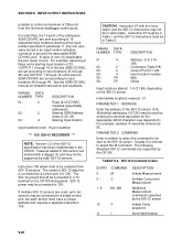
...sent to the SDI-12 sensor. PARAMETER 2. The following Standard SDI-12 commands are set according to be supported by the CR10X: TABLE 9-8. INPUT/OUTPUT INSTRUCTIONS possible to input locations 49 through 64. For example, assuming 2 Reps and a starting at the input... 2 Control Port (C1-C8) 04: 4 Input location number 05: FP Mult 06: FP Offset Input locations altered: 1-9 (†1-99), depending on the CR10X wiring panel. SDI-12 Command Codes ENTRY COMMAND 0 M 0 -- Features added in Table 1 and the SDI-12 instructions must be connected to a "G" terminal on the...
...sent to the SDI-12 sensor. PARAMETER 2. The following Standard SDI-12 commands are set according to be supported by the CR10X: TABLE 9-8. INPUT/OUTPUT INSTRUCTIONS possible to input locations 49 through 64. For example, assuming 2 Reps and a starting at the input... 2 Control Port (C1-C8) 04: 4 Input location number 05: FP Mult 06: FP Offset Input locations altered: 1-9 (†1-99), depending on the CR10X wiring panel. SDI-12 Command Codes ENTRY COMMAND 0 M 0 -- Features added in Table 1 and the SDI-12 instructions must be connected to a "G" terminal on the...