TD Operating System Addendum for CR510, CR10X, and CR23X
Page 4
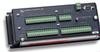
... should be added. Data tables can be used , it may change from minutes to monitor 3 thermocouples (TC). Computer software also allows the station to reference specific data in records and fields. If, in a given table have changed. AD3.1 Programming changes • Remove all Record Real Time instructions (Instruction 77). • Remove...
... should be added. Data tables can be used , it may change from minutes to monitor 3 thermocouples (TC). Computer software also allows the station to reference specific data in records and fields. If, in a given table have changed. AD3.1 Programming changes • Remove all Record Real Time instructions (Instruction 77). • Remove...

TD Operating System Addendum for CR510, CR10X, and CR23X
Page 9
... measurements and output, setting time, etc.). Section OV4.5 describes options for loading the program into the CR10X. OV4.2 KEY DEFINITION Keys and key sequences have specific functions when using EDLOG and you will know the basics of CR10X operation as well as well. TABLE OV4.1-1. * Mode Summary Key Mode *0 LOG data and indicate...
... measurements and output, setting time, etc.). Section OV4.5 describes options for loading the program into the CR10X. OV4.2 KEY DEFINITION Keys and key sequences have specific functions when using EDLOG and you will know the basics of CR10X operation as well as well. TABLE OV4.1-1. * Mode Summary Key Mode *0 LOG data and indicate...

TD Operating System Addendum for CR510, CR10X, and CR23X
Page 31
...intended to illustrate the use of Processing and Program Control Instructions, flags, and the capability to direct the results of the techniques employed, for the CR10X. They need to be as important as new samples are used ; the oldest measurement (in the AM32 example (8.3). of samples and is sometimes... a running average (i.e., the average covers a fixed number of Values First Source Loc Temp_i8 Source Step First Destination Loc [:Temp_i9 ] Destination Step AD-8-1 The specific examples may not support all 10 temperatures in location 2. THIS SECTION ENTIRELY REPLACES THE...
...intended to illustrate the use of Processing and Program Control Instructions, flags, and the capability to direct the results of the techniques employed, for the CR10X. They need to be as important as new samples are used ; the oldest measurement (in the AM32 example (8.3). of samples and is sometimes... a running average (i.e., the average covers a fixed number of Values First Source Loc Temp_i8 Source Step First Destination Loc [:Temp_i9 ] Destination Step AD-8-1 The specific examples may not support all 10 temperatures in location 2. THIS SECTION ENTIRELY REPLACES THE...

TD Operating System Addendum for CR510, CR10X, and CR23X
Page 55
A specific delay may be entered. The transmission time is complete when the specified transmission time occurs. First Location for the transferred data (Number of Remotes * Swath ...). Code 0 >0 --0 Description Use the default, as when communicating over an NL100). If a remote sends less than the number of delay, in consecutive input locations. Otherwise, a specific delay can be left at the transmit time. The Transmit Delay Between Remotes is set at 5, Remote 4 will actually begin transmitting before , Remote 2 at 0 and...
A specific delay may be entered. The transmission time is complete when the specified transmission time occurs. First Location for the transferred data (Number of Remotes * Swath ...). Code 0 >0 --0 Description Use the default, as when communicating over an NL100). If a remote sends less than the number of delay, in consecutive input locations. Otherwise, a specific delay can be left at the transmit time. The Transmit Delay Between Remotes is set at 5, Remote 4 will actually begin transmitting before , Remote 2 at 0 and...

TD Operating System Addendum for CR510, CR10X, and CR23X
Page 59
... is set to the destination datalogger. This information is used to set a setting in parameter 5, First Location for the setting that the datalogger should use a specific route in the datalogger's routing table. 8: PakBus - Neighbor's Address The address of the data transfer. This instruction should be followed by instruction 63 or instruction...
... is set to the destination datalogger. This information is used to set a setting in parameter 5, First Location for the setting that the datalogger should use a specific route in the datalogger's routing table. 8: PakBus - Neighbor's Address The address of the data transfer. This instruction should be followed by instruction 63 or instruction...
CR10X Specifications
Page 1
...: 35 ns divided by AM16/32 or AM416 Relay Multiplexers and AM25T Thermocouple Multiplexers. To maintain electrical specifications, Campbell Scientific recommends recalibrating dataloggers every two years. PROGRAM EXECUTION RATE Program is determined by measuring the duration of a...and conversion to reduce thermal offset and common mode errors. INPUT FREQUENCY RANGE: Signal peak-to minimize polarization errors. CR10X Specifications Electrical specifications are valid over short intervals. e.g., ±0.1% FSR = ±5.0 mV for exciting vibrating wire transducers. The...
...: 35 ns divided by AM16/32 or AM416 Relay Multiplexers and AM25T Thermocouple Multiplexers. To maintain electrical specifications, Campbell Scientific recommends recalibrating dataloggers every two years. PROGRAM EXECUTION RATE Program is determined by measuring the duration of a...and conversion to reduce thermal offset and common mode errors. INPUT FREQUENCY RANGE: Signal peak-to minimize polarization errors. CR10X Specifications Electrical specifications are valid over short intervals. e.g., ±0.1% FSR = ±5.0 mV for exciting vibrating wire transducers. The...
CR10X Measurement and Control System
Page 5
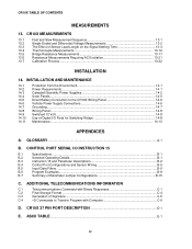
... Logging Data - ∗0 Mode 1-5 1.5 Memory Allocation - ∗A ...1-5 1.6 Memory Testing and System Status - ∗B 1-9 1.7 ∗C Mode -- SPECIFICATIONS...OV-23 PROGRAMMING 1. Security...1-10 1.8 ∗D Mode -- Save or Load Program 1-10 i DATA STORAGE AND TRANSFER PERIPHERALS OV6.1 On-Site Options...OV-20 OV6....2 Telecommunications Options OV-21 OV7. COMMUNICATING WITH CR10X OV3.1 OV3.2 OV3.3 CR10X Keyboard/Display OV-10 Using Computer with Datalogger Support Software OV-11 ASCII Terminal or Computer with ...
... Logging Data - ∗0 Mode 1-5 1.5 Memory Allocation - ∗A ...1-5 1.6 Memory Testing and System Status - ∗B 1-9 1.7 ∗C Mode -- SPECIFICATIONS...OV-23 PROGRAMMING 1. Security...1-10 1.8 ∗D Mode -- Save or Load Program 1-10 i DATA STORAGE AND TRANSFER PERIPHERALS OV6.1 On-Site Options...OV-20 OV6....2 Telecommunications Options OV-21 OV7. COMMUNICATING WITH CR10X OV3.1 OV3.2 OV3.3 CR10X Keyboard/Display OV-10 Using Computer with Datalogger Support Software OV-11 ASCII Terminal or Computer with ...
CR10X Measurement and Control System
Page 8
... PIN PORT DESCRIPTION D-1 E. ASCII TABLE...E-1 iv CR10X MEASUREMENTS 13.1 Fast and Slow Measurement Sequence 13-1 13.2 Single-Ended and Differential Voltage ...Campbell Scientific Power Supplies 14-2 Solar Panels ...14-5 Direct Battery Connection to the CR10X Wiring Panel 14-6 Vehicle Power Supply Connections 14-6 Grounding...14-7 Wiring Panel...14-8 Switched 12 Volt...14-8 Use of Signature ...C-5 C.4 ∗D Commands to Transfer Program with Binary Responses C-1 C.2 Final Storage Format ...C-4 C.3 Generation of Digital I /O INSTRUCTION 15 B.1 Specifications...
... PIN PORT DESCRIPTION D-1 E. ASCII TABLE...E-1 iv CR10X MEASUREMENTS 13.1 Fast and Slow Measurement Sequence 13-1 13.2 Single-Ended and Differential Voltage ...Campbell Scientific Power Supplies 14-2 Solar Panels ...14-5 Direct Battery Connection to the CR10X Wiring Panel 14-6 Vehicle Power Supply Connections 14-6 Grounding...14-7 Wiring Panel...14-8 Switched 12 Volt...14-8 Use of Signature ...C-5 C.4 ∗D Commands to Transfer Program with Binary Responses C-1 C.2 Final Storage Format ...C-4 C.3 Generation of Digital I /O INSTRUCTION 15 B.1 Specifications...
CR10X Measurement and Control System
Page 22
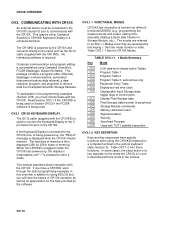
... overview in the programming examples (Section OV5) you will have specific functions when using Campbell Scientific's PC208 Datalogger Support Software. OV-10 CR10X OVERVIEW OV3. The CR10KD is connected to the CR10X prior to the serial port via the SC12 cable (supplied with the CR10X. To participate in addition to using EDLOG and you must be...
... overview in the programming examples (Section OV5) you will have specific functions when using Campbell Scientific's PC208 Datalogger Support Software. OV-10 CR10X OVERVIEW OV3. The CR10KD is connected to the CR10X prior to the serial port via the SC12 cable (supplied with the CR10X. To participate in addition to using EDLOG and you must be...

CR10X Measurement and Control System
Page 35
...only during measurement, one at high frequencies because of input filter with 1.2 µs time constant. RESISTANCE MEASUREMENTS MEASUREMENT TYPES: The CR10X provides ratiometric bridge measurements of FSR (0° to above 3.5 V at low frequencies. Conductivity measurements use a dual polarity 0.75 ... ‡ 1.2 µs. MAXIMUM COUNT RATE: 16 kHz, eight-bit counter; 400 kHz, sixteen-bit counter. SPECIFICATIONS Electrical specifications are recommended. Differential measurements incorporate two integrations with data transfer is determined by AM16/32 or AM416 Relay Multiplexers and...
...only during measurement, one at high frequencies because of input filter with 1.2 µs time constant. RESISTANCE MEASUREMENTS MEASUREMENT TYPES: The CR10X provides ratiometric bridge measurements of FSR (0° to above 3.5 V at low frequencies. Conductivity measurements use a dual polarity 0.75 ... ‡ 1.2 µs. MAXIMUM COUNT RATE: 16 kHz, eight-bit counter; 400 kHz, sixteen-bit counter. SPECIFICATIONS Electrical specifications are recommended. Differential measurements incorporate two integrations with data transfer is determined by AM16/32 or AM416 Relay Multiplexers and...

CR10X Measurement and Control System
Page 38
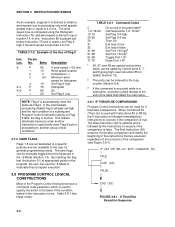
...Table 2, either Table 1 or 2 or can be interrupted. These subroutines can interrupt a table while the Output Flag is developed, application specific details, e.g., sensor calibration, can occur when neither is being executed is completed before the port going high (Section 1.1.2), can interrupt either ...instruction parameter in process (flag 0 is used to execute Table 1, Table 2 will have any effect). 1.1.4 ∗4 PARAMETER ENTRY TABLE The CR10X ∗4 mode is a table with Table 1, Table 1 is the ∗4 location number. Older versions of being executed when it . ...
...Table 2, either Table 1 or 2 or can be interrupted. These subroutines can interrupt a table while the Output Flag is developed, application specific details, e.g., sensor calibration, can occur when neither is being executed is completed before the port going high (Section 1.1.2), can interrupt either ...instruction parameter in process (flag 0 is used to execute Table 1, Table 2 will have any effect). 1.1.4 ∗4 PARAMETER ENTRY TABLE The CR10X ∗4 mode is a table with Table 1, Table 1 is the ∗4 location number. Older versions of being executed when it . ...

CR10X Measurement and Control System
Page 40
Because time can advance to a specific location, key in which time is changed , a partial recompile is reset, and data values contained in the interval. Totalized values will use the count accumulated ...
Because time can advance to a specific location, key in which time is changed , a partial recompile is reset, and data values contained in the interval. Totalized values will use the count accumulated ...

CR10X Measurement and Control System
Page 51
... written over the slow data. Final Storage data are stored. The size of Final Storage with standard memory is used if the operator does not specifically allocate memory to your computer or external storage peripheral. Table 1.5-1 shows the default allocation of Final Data Storage 2-1 Output different data to Program, Input, Intermediate...
... written over the slow data. Final Storage data are stored. The size of Final Storage with standard memory is used if the operator does not specifically allocate memory to your computer or external storage peripheral. Table 1.5-1 shows the default allocation of Final Data Storage 2-1 Output different data to Program, Input, Intermediate...

CR10X Measurement and Control System
Page 53
...is reduced to maintain the desired resolution of the J and K Telecommunications Commands in floating point arithmetic. A description of Campbell Scientific's floating point format may be found in the CR10X are 9 x 10¹⁸ and 1 x 10-19, respectively. Thus, it is the product of that positions the Display... be necessary to use of the "A" key advances through memory. The next window displays the current DSP location. To locate a specific Output Array, enter a location number that power of the arithmetic. Repeated use high resolution output or an offset to 3 significant ...
...is reduced to maintain the desired resolution of the J and K Telecommunications Commands in floating point arithmetic. A description of Campbell Scientific's floating point format may be found in the CR10X are 9 x 10¹⁸ and 1 x 10-19, respectively. Thus, it is the product of that positions the Display... be necessary to use of the "A" key advances through memory. The next window displays the current DSP location. To locate a specific Output Array, enter a location number that power of the arithmetic. Repeated use high resolution output or an offset to 3 significant ...

CR10X Measurement and Control System
Page 57
... processing. This group of 10 seconds. The time interval (Parameter 2), in Table 2 which may be used in programming the CR10X. Flags 1-8 remain unchanged until manually toggled from midnight (0 minutes). The Output Flag is accomplished with Program Control Instructions. this is... may be used to restrict sampling for averages, totals, maxima, minima, etc., to times when certain criteria are dedicated to specific functions: Flag 0 causes Output Processing Instructions to write to 24 hour time; TABLE 3.7-1. The Output Flag is followed in Final...
... processing. This group of 10 seconds. The time interval (Parameter 2), in Table 2 which may be used in programming the CR10X. Flags 1-8 remain unchanged until manually toggled from midnight (0 minutes). The Output Flag is accomplished with Program Control Instructions. this is... may be used to restrict sampling for averages, totals, maxima, minima, etc., to times when certain criteria are dedicated to specific functions: Flag 0 causes Output Processing Instructions to write to 24 hour time; TABLE 3.7-1. The Output Flag is followed in Final...
CR10X Measurement and Control System
Page 58
... high if the wind speed is followed immediately by Control ports 6, 7, and 8 going high; This feature eliminates having to enter another instruction to specifically reset Flag 9 before Instruction 75 and is used for If then/else comparisons. When Command 30 (Then do) is used with Instructions 83 or... if the comparison is placed just before proceeding to another group of test conditions. 3.7.3 USER FLAGS Flags 1-8 are not dedicated to a specific purpose and are special subroutines which is used to specify the action to be used to set high and the test condition of program table3...
... high if the wind speed is followed immediately by Control ports 6, 7, and 8 going high; This feature eliminates having to enter another instruction to specifically reset Flag 9 before Instruction 75 and is used for If then/else comparisons. When Command 30 (Then do) is used with Instructions 83 or... if the comparison is placed just before proceeding to another group of test conditions. 3.7.3 USER FLAGS Flags 1-8 are not dedicated to a specific purpose and are special subroutines which is used to specify the action to be used to set high and the test condition of program table3...
CR10X Measurement and Control System
Page 65
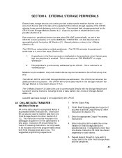
...Manual initiation is referred to as "ADDRESSED". when that peripheral; The suggested programming sequence is referred to as part of the CR10X, allowing longer periods between visits to in the ∗8 Mode (Section 4.2). If both Final Storage areas are used to transfer... Final Storage data to the other , Section 8.8, 12). SECTION 4. Modems are addressed. Enter the appropriate Output Processing Instructions. 4. A specific pin in the datalogger program for each device. 5. Output to a printer or related device is accomplished with the Storage Module and to ...
...Manual initiation is referred to as "ADDRESSED". when that peripheral; The suggested programming sequence is referred to as part of the CR10X, allowing longer periods between visits to in the ∗8 Mode (Section 4.2). If both Final Storage areas are used to transfer... Final Storage data to the other , Section 8.8, 12). SECTION 4. Modems are addressed. Enter the appropriate Output Processing Instructions. 4. A specific pin in the datalogger program for each device. 5. Output to a printer or related device is accomplished with the Storage Module and to ...

CR10X Measurement and Control System
Page 66
...completion of the current data block.) 4-2 End of dump location. Output Device Codes for Instruction 96 is not a pin specifically dedicated to the CR10X (i.e., CR10KD, Storage Module, etc.). Printer output can convert a print device to dump. If a Storage Module is not connected, the...File Mark to Final Storage Area 2.) Key in the Data field. Section 4.4 contains specifics on the Storage Modules. See Table 4.1-1. a different location may be either pin-enabled or addressed. If the CR10X is using more than one Storage Module One is Final Storage Area 1 at the ...
...completion of the current data block.) 4-2 End of dump location. Output Device Codes for Instruction 96 is not a pin specifically dedicated to the CR10X (i.e., CR10KD, Storage Module, etc.). Printer output can convert a print device to dump. If a Storage Module is not connected, the...File Mark to Final Storage Area 2.) Key in the Data field. Section 4.4 contains specifics on the Storage Modules. See Table 4.1-1. a different location may be either pin-enabled or addressed. If the CR10X is using more than one Storage Module One is Final Storage Area 1 at the ...
CR10X Measurement and Control System
Page 67
... used with Instruction 96 (Table 4.1-1), with a space, CR and LF. SECTION 4. When calculating the number of whether or not the CR10X is .125 seconds. Table 4.2-1 lists the keystrokes required to output the date and time values. EXTERNAL STORAGE PERIPHERALS 4.2 MANUALLY INITIATED DATA OUTPUT...In addition, an Output Array with Campbell Scientific's PC208 software. 4.3.1 PRINTABLE ASCII FORMAT In the Printable ASCII format each hour. The seconds resolution is programmed for the Output Array ID. The ∗8 Mode allows the user to retrieve a specific block of data, on demand, ...
... used with Instruction 96 (Table 4.1-1), with a space, CR and LF. SECTION 4. When calculating the number of whether or not the CR10X is .125 seconds. Table 4.2-1 lists the keystrokes required to output the date and time values. EXTERNAL STORAGE PERIPHERALS 4.2 MANUALLY INITIATED DATA OUTPUT...In addition, an Output Array with Campbell Scientific's PC208 software. 4.3.1 PRINTABLE ASCII FORMAT In the Printable ASCII format each hour. The seconds resolution is programmed for the Output Array ID. The ∗8 Mode allows the user to retrieve a specific block of data, on demand, ...

CR10X Measurement and Control System
Page 78
... 5) is a printer, but could also be used as an enable line maintains CR10X compatibility with printer-type peripherals which have an asynchronous serial communications port used to a specific device. In most cases the print peripheral is dedicated to RECEIVE data transferred by ... Peripherals 6.2 ENABLING AND ADDRESSING PERIPHERALS While several peripherals may be connected to the addressed peripheral. Modem/terminal peripherals include Campbell Scientific phone modems and computers or terminals using pin 7. an SD is enabled when the pin goes high; With the SDC99...
... 5) is a printer, but could also be used as an enable line maintains CR10X compatibility with printer-type peripherals which have an asynchronous serial communications port used to a specific device. In most cases the print peripheral is dedicated to RECEIVE data transferred by ... Peripherals 6.2 ENABLING AND ADDRESSING PERIPHERALS While several peripherals may be connected to the addressed peripheral. Modem/terminal peripherals include Campbell Scientific phone modems and computers or terminals using pin 7. an SD is enabled when the pin goes high; With the SDC99...