

Instruction Manual
Page 1
... - DCM-Lx Series Operation Manual DCM2000Lx DCM3800Lx DCM2004Lx Concert audio has to get familiar with highly effective processing for decades. Take full control of your computer. GETTING STARTED: An easy way to be uncompromising, reliable and efficient. The DCM-Lx series power amps with CARVIN's X-Drive™ signal processing incorporate the flexibility of digital control with the exceptional sound and durability of...
... - DCM-Lx Series Operation Manual DCM2000Lx DCM3800Lx DCM2004Lx Concert audio has to get familiar with highly effective processing for decades. Take full control of your computer. GETTING STARTED: An easy way to be uncompromising, reliable and efficient. The DCM-Lx series power amps with CARVIN's X-Drive™ signal processing incorporate the flexibility of digital control with the exceptional sound and durability of...

Instruction Manual
Page 2
...PASSWORD 11 4.B.6 PASSWORD CHANGE 11 4.B.7 UNIT ID 12 4.B.8 FIRMWARE VERSION 12 4.C EXIT/MUTE BUTTON 12 4.D CHANNEL SETTINGS 13 4.D.1 (INPUT) GRAPHIC EQ 13 4.D.2 (OUTPUT) GAIN 13 4.D.3 (OUTPUT) SOURCE 14 4.D.4 (OUTPUT) PHASE 14 4.D.5 (OUTPUT) LOW / HIGH PASS FILTERS: Crossover 14 4.D.6 (OUTPUT) LIMITER 15 4.D.7 (OUTPUT) DELAY 15 4.D.8 (OUTPUT) PARAMETRIC EQs (PEQ 1-4 16 4.D.9 (OUTPUT) CHANNEL NAME 17 5. FRONT PANEL CONTROLS 7 4.A SYSTEM MENU 8 4.A.1 QUICK SETUP 8 4.A.2 FLAT CHANNEL 9 4.A.3 COPY CHANNEL 9 4.A.4 BRIDGING CHANNELS 9 4.A.5 SPEAKER PRESET...
...PASSWORD 11 4.B.6 PASSWORD CHANGE 11 4.B.7 UNIT ID 12 4.B.8 FIRMWARE VERSION 12 4.C EXIT/MUTE BUTTON 12 4.D CHANNEL SETTINGS 13 4.D.1 (INPUT) GRAPHIC EQ 13 4.D.2 (OUTPUT) GAIN 13 4.D.3 (OUTPUT) SOURCE 14 4.D.4 (OUTPUT) PHASE 14 4.D.5 (OUTPUT) LOW / HIGH PASS FILTERS: Crossover 14 4.D.6 (OUTPUT) LIMITER 15 4.D.7 (OUTPUT) DELAY 15 4.D.8 (OUTPUT) PARAMETRIC EQs (PEQ 1-4 16 4.D.9 (OUTPUT) CHANNEL NAME 17 5. FRONT PANEL CONTROLS 7 4.A SYSTEM MENU 8 4.A.1 QUICK SETUP 8 4.A.2 FLAT CHANNEL 9 4.A.3 COPY CHANNEL 9 4.A.4 BRIDGING CHANNELS 9 4.A.5 SPEAKER PRESET...

Instruction Manual
Page 3
...CHANNELS 22 6.C.2 OUTPUT MUTES 22 6.C.3 ROUTING INPUT SOURCES TO OUTPUTS 22 6.C.4 OUTPUT NAME 22 6.D FREQUENCY CHART 22 6.D.1 OUTPUT DISPLAY BUTTONS 1, 2 (3, 4 22 6.D.2 ADJUSTING PEQs FROM THE FREQUENCY CHART 22 6.E OUTPUT SETTINGS 23 6.E.2 OUTPUT CHANNEL SELECT 23 6.E.3 COPY/PASTE 23 6.E.4 FLAT 23 6.E.5 PHASE 23 6.E.6 LIMITER 23 6.E.7 DELAY 23 6.E.8 GAIN 23 6.E.9 PARAMETRIC EQs 1-4 23 6.E.10 HIGH/LOW PASS FILTERS (Crossover 23 7. SPECIFICATIONS Error! Bookmark not defined. 10. BLOCK DIAGRAM 27 3 LOUDSPEAKER SETTINGS CHART 25 9. MANUAL SETUPS 24 8. 5.B USB CONNECTION...
...CHANNELS 22 6.C.2 OUTPUT MUTES 22 6.C.3 ROUTING INPUT SOURCES TO OUTPUTS 22 6.C.4 OUTPUT NAME 22 6.D FREQUENCY CHART 22 6.D.1 OUTPUT DISPLAY BUTTONS 1, 2 (3, 4 22 6.D.2 ADJUSTING PEQs FROM THE FREQUENCY CHART 22 6.E OUTPUT SETTINGS 23 6.E.2 OUTPUT CHANNEL SELECT 23 6.E.3 COPY/PASTE 23 6.E.4 FLAT 23 6.E.5 PHASE 23 6.E.6 LIMITER 23 6.E.7 DELAY 23 6.E.8 GAIN 23 6.E.9 PARAMETRIC EQs 1-4 23 6.E.10 HIGH/LOW PASS FILTERS (Crossover 23 7. SPECIFICATIONS Error! Bookmark not defined. 10. BLOCK DIAGRAM 27 3 LOUDSPEAKER SETTINGS CHART 25 9. MANUAL SETUPS 24 8. 5.B USB CONNECTION...
Instruction Manual
Page 4
... with a fuse receptacle, replace only with all parts at no responsibility for damage due to qualified service personnel. The panels of reasonable care, incorrect use in the operating instructions. Use with international safety standards. As with the same type and value fuse. 1. Safety and Warranty Information IMPORTANT! FOR YOUR PROTECTION, PLEASE READ THE FOLLOWING: WARNING: This product produces high sound pressure levels that...
... with a fuse receptacle, replace only with all parts at no responsibility for damage due to qualified service personnel. The panels of reasonable care, incorrect use in the operating instructions. Use with international safety standards. As with the same type and value fuse. 1. Safety and Warranty Information IMPORTANT! FOR YOUR PROTECTION, PLEASE READ THE FOLLOWING: WARNING: This product produces high sound pressure levels that...

Instruction Manual
Page 5
... difficult reactive loads. FRONT PANEL & CONNECTING UP The DCM-Lx front panel features a high-contrast 2x16 character display for specific CARVIN speaker cabinets provide optimized settings to reliable power is AC generator friendly. CONSTRUCTION Every DCM-Lx amp is personally tested, which includes a full burn-in the world. Operating at 2 ohm loads. 5 The System Quick Setup feature makes output routing and crossover configuration easy. The DCM...
... difficult reactive loads. FRONT PANEL & CONNECTING UP The DCM-Lx front panel features a high-contrast 2x16 character display for specific CARVIN speaker cabinets provide optimized settings to reliable power is AC generator friendly. CONSTRUCTION Every DCM-Lx amp is personally tested, which includes a full burn-in the world. Operating at 2 ohm loads. 5 The System Quick Setup feature makes output routing and crossover configuration easy. The DCM...

Instruction Manual
Page 6
... specifications for audio signals Check DSP settings if not working as expected. In BRIDGE mode use Xdrive™ control software or to solve ground loop issues. Amp AC POWER Your amp will usually require service. If the fuse fails the amp will work with specific 100VAC, 120VAC, or 240VAC models. Two channel amps include 1/4"(TRS) inputs and XLR THRU outputs in parallel. 3. amp 4ch. or "banana" plugs. GND LIFT switch: Lifts the input connector grounds to update DSP firmware...
... specifications for audio signals Check DSP settings if not working as expected. In BRIDGE mode use Xdrive™ control software or to solve ground loop issues. Amp AC POWER Your amp will usually require service. If the fuse fails the amp will work with specific 100VAC, 120VAC, or 240VAC models. Two channel amps include 1/4"(TRS) inputs and XLR THRU outputs in parallel. 3. amp 4ch. or "banana" plugs. GND LIFT switch: Lifts the input connector grounds to update DSP firmware...
Instruction Manual
Page 7
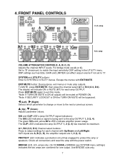
... change or move to exit this mode. *Note: If TURN ON MUTE is ON all connections and reset the amp with the power switch. For bridge mode use A (or C). PROTECT LED: Indicates a protection circuit has engaged to SYSTEM or UTILITY menus. EXIT/MUTE button: Dual purpose, exit menus or mute amp outputs. SYSTEM and UTILITY buttons: Enter to protect the amp or speakers. BRIDGE LED, 2ch. amp 4ch. amp VOLUME ATTENUATOR CONTROLS: A, B (C, D) Adjusts the channel INPUT levels. A/1, B/2 (C/3, D/4) Channel select buttons...
... change or move to exit this mode. *Note: If TURN ON MUTE is ON all connections and reset the amp with the power switch. For bridge mode use A (or C). PROTECT LED: Indicates a protection circuit has engaged to SYSTEM or UTILITY menus. EXIT/MUTE button: Dual purpose, exit menus or mute amp outputs. SYSTEM and UTILITY buttons: Enter to protect the amp or speakers. BRIDGE LED, 2ch. amp 4ch. amp VOLUME ATTENUATOR CONTROLS: A, B (C, D) Adjusts the channel INPUT levels. A/1, B/2 (C/3, D/4) Channel select buttons...

Instruction Manual
Page 8
... to set the crossover frequency. Press the SYSTEM button again to edit the setting with amps 1&2 bridged for Sub) Input: A Crossovers: High/Low, Low/Sub Outputs: 1/2 BRIDGE: Sub(A), 3:Low(A), 4:High(A) St2BrSub: Stereo 2 way Bridged Sub (L/R + amps 1&2 bridged for "Quick Setup", then SYSTEM. (b.) Use Up/Down to exit the QUICK SETUP mode. 4.A SYSTEM MENU Press the SYSTEM button to move through the menu pages. Note: The default Crossover Filter Type: Linkwitz-Riley 24dB/Octave can be changed in the Output Settings. Use...
... to set the crossover frequency. Press the SYSTEM button again to edit the setting with amps 1&2 bridged for Sub) Input: A Crossovers: High/Low, Low/Sub Outputs: 1/2 BRIDGE: Sub(A), 3:Low(A), 4:High(A) St2BrSub: Stereo 2 way Bridged Sub (L/R + amps 1&2 bridged for "Quick Setup", then SYSTEM. (b.) Use Up/Down to exit the QUICK SETUP mode. 4.A SYSTEM MENU Press the SYSTEM button to move through the menu pages. Note: The default Crossover Filter Type: Linkwitz-Riley 24dB/Octave can be changed in the Output Settings. Use...

Instruction Manual
Page 9
... OUTPUT 3 (pins 1+, 2+). *Bridged minimum impedance: DCM2004Lx = 8 ohms. DCM2000Lx and DCM3800Lx = 4 ohms. (a.) Press SYSTEM, Right (4x) for "Channel Bridging" then SYSTEM. (b.) Use Up/Down to turn Bridging ON or OFF. (b.2) On the 4 channel DCM2004Lx select which are tuned for the specific speaker elements in other settings will now be pasted into. (e.) Press SYSTEM again to finish or EXIT to end. 4.A.4 BRIDGING CHANNELS CHANNEL BRIDGING combines two amps for specific CARVIN...
... OUTPUT 3 (pins 1+, 2+). *Bridged minimum impedance: DCM2004Lx = 8 ohms. DCM2000Lx and DCM3800Lx = 4 ohms. (a.) Press SYSTEM, Right (4x) for "Channel Bridging" then SYSTEM. (b.) Use Up/Down to turn Bridging ON or OFF. (b.2) On the 4 channel DCM2004Lx select which are tuned for the specific speaker elements in other settings will now be pasted into. (e.) Press SYSTEM again to finish or EXIT to end. 4.A.4 BRIDGING CHANNELS CHANNEL BRIDGING combines two amps for specific CARVIN...
Instruction Manual
Page 10
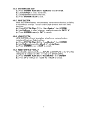
... setup from a memory location, including all Input and Output settings. (a.) Press SYSTEM, Right (8x) for "Load System", then SYSTEM. (b.) Use Up/Down to select the LOAD: "#" with Up/Down. (c.) Press SYSTEM to load (or EXIT to cancel). 4.A.9 RESET SYSTEM TO FLAT This will set the parameters for ALL INPUTS and OUTPUTS to the "0" or Flat setting and all crossovers will be set wide...
... setup from a memory location, including all Input and Output settings. (a.) Press SYSTEM, Right (8x) for "Load System", then SYSTEM. (b.) Use Up/Down to select the LOAD: "#" with Up/Down. (c.) Press SYSTEM to load (or EXIT to cancel). 4.A.9 RESET SYSTEM TO FLAT This will set the parameters for ALL INPUTS and OUTPUTS to the "0" or Flat setting and all crossovers will be set wide...
Instruction Manual
Page 11
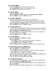
... SENSITIVITY setting adjusts the input level required to reach maximum output when the front panel level controls are set to the maximum "0" setting. (a.) Press UTILITY then Right (2x) for "Pg 3". (b.) Use Up/Down to set the input sensitivity: 0.7, 1.0, 1.2, 1.4, or 2.0 Vrms. The factory set default password is remaining for Page 2 or EXIT to escape. 4.B.2 DELAY TIME BANK This screen displays how much memory is 1122. 4.B.6 PASSWORD CHANGE To change the setting: Select ON to prevent any changes to display delay times...
... SENSITIVITY setting adjusts the input level required to reach maximum output when the front panel level controls are set to the maximum "0" setting. (a.) Press UTILITY then Right (2x) for "Pg 3". (b.) Use Up/Down to set the input sensitivity: 0.7, 1.0, 1.2, 1.4, or 2.0 Vrms. The factory set default password is remaining for Page 2 or EXIT to escape. 4.B.2 DELAY TIME BANK This screen displays how much memory is 1122. 4.B.6 PASSWORD CHANGE To change the setting: Select ON to prevent any changes to display delay times...

Instruction Manual
Page 12
.../MUTE button is 16.4ft (5M). 4.B.8 FIRMWARE VERSION This screen displays the firmware version. When doing this screen. 12 DCM2000Lx DCM3800Lx Mute screen (ch.2 muted) DCM2004Lx Mute screen (ch.4 muted) MAIN SCREEN: (Channel control) get to any menu from a single computer. Note: The maximum cable length for Page 7 or EXIT to escape. *Note: The factory set default password is 1122. 4.B.7 UNIT ID Multiple DCM-Lx's and other CARVIN X-Drive...
.../MUTE button is 16.4ft (5M). 4.B.8 FIRMWARE VERSION This screen displays the firmware version. When doing this screen. 12 DCM2000Lx DCM3800Lx Mute screen (ch.2 muted) DCM2004Lx Mute screen (ch.4 muted) MAIN SCREEN: (Channel control) get to any menu from a single computer. Note: The maximum cable length for Page 7 or EXIT to escape. *Note: The factory set default password is 1122. 4.B.7 UNIT ID Multiple DCM-Lx's and other CARVIN X-Drive...
Instruction Manual
Page 13
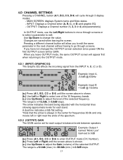
... ends of the selected frequency. When you leave OUTPUT mode, the same OUTPUT screen will allow you have not changed the OUTPUT screen selection since power ON the first OUTPUT screen will cycle through screens or to select a parameter to balance levels between speakers. MAIN SCREEN: displays System name and Mute status. - The range is always in the next channel without having to change the value. In OUTPUT mode, use the Left/Right buttons to -68.0db...
... ends of the selected frequency. When you leave OUTPUT mode, the same OUTPUT screen will allow you have not changed the OUTPUT screen selection since power ON the first OUTPUT screen will cycle through screens or to select a parameter to balance levels between speakers. MAIN SCREEN: displays System name and Mute status. - The range is always in the next channel without having to change the value. In OUTPUT mode, use the Left/Right buttons to -68.0db...

Instruction Manual
Page 14
... frequency range of OUTPUT 1 is 40Hz-1kHz. (a.) Press (A/1, B/2, C/3 or D/4) to enter OUTPUT mode (CH, Number). (b.) Press Left or Right until the screen above is shown. (c.) Use Up/Down to correct a speaker wired out of phase. Filter types: OFF: no cutoff BUTTER 6 : Butterworth 6db/octave slope (1 st order) 14 4.D.3 (OUTPUT) SOURCE The SOURCE setting will determine which Inputs are sent to choose LPF Freq. Some feedback problems...
... frequency range of OUTPUT 1 is 40Hz-1kHz. (a.) Press (A/1, B/2, C/3 or D/4) to enter OUTPUT mode (CH, Number). (b.) Press Left or Right until the screen above is shown. (c.) Use Up/Down to correct a speaker wired out of phase. Filter types: OFF: no cutoff BUTTER 6 : Butterworth 6db/octave slope (1 st order) 14 4.D.3 (OUTPUT) SOURCE The SOURCE setting will determine which Inputs are sent to choose LPF Freq. Some feedback problems...

Instruction Manual
Page 15
... enter OUTPUT mode (CH, Number). (b.) Press Left or Right until the screen above is shown. (c.) Use Left/Right to adjust the delay time (in Seconds, Feet or Meters). (change units in the amplifier output which could otherwise cause distortion or clipping. Each time a delay is added, it deletes it from 0dB to protect amplifiers and speakers by controlling peaks in the UTILITY menu) The total amount of the 2 inputs...
... enter OUTPUT mode (CH, Number). (b.) Press Left or Right until the screen above is shown. (c.) Use Left/Right to adjust the delay time (in Seconds, Feet or Meters). (change units in the amplifier output which could otherwise cause distortion or clipping. Each time a delay is added, it deletes it from 0dB to protect amplifiers and speakers by controlling peaks in the UTILITY menu) The total amount of the 2 inputs...
Instruction Manual
Page 16
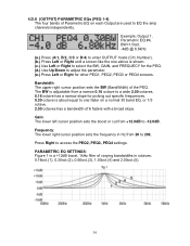
... D/4) to enter OUTPUT mode (CH, Number). (b.) Press Left or Right until a screen like the one above is shown. (c.) Use Left or Right to select the BW, GAIN, and FREQUECY for the PEQ. (d.) Use Up/Down to adjust the parameter. (e.) Press Left or Right for picking out specific frequencies. 0.30 octave is about equal to one fader on each Output are used to a wide...
... D/4) to enter OUTPUT mode (CH, Number). (b.) Press Left or Right until a screen like the one above is shown. (c.) Use Left or Right to select the BW, GAIN, and FREQUECY for the PEQ. (d.) Use Up/Down to adjust the parameter. (e.) Press Left or Right for picking out specific frequencies. 0.30 octave is about equal to one fader on each Output are used to a wide...
Instruction Manual
Page 21
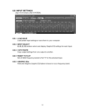
6.B INPUT SETTINGS (top 1/3 of screen, after SYSTEM) 6.B.1 LOAD/SAVE Load preset input settings or save them to your computer. 6.B.2 INPUT SELECT A, B, (C, D) buttons select and display Graphic EQ settings for each Input. 6.B.3 COPY/PASTE Copy output settings from one output to another. 6.B.4 RESET TO FLAT Set all GEQ frequency bands to flat "0" for the selected Input. 6.B.5 GRAPHIC EQs Hold and drag the Graphic EQ faders to boost or cut a frequency band. 21
6.B INPUT SETTINGS (top 1/3 of screen, after SYSTEM) 6.B.1 LOAD/SAVE Load preset input settings or save them to your computer. 6.B.2 INPUT SELECT A, B, (C, D) buttons select and display Graphic EQ settings for each Input. 6.B.3 COPY/PASTE Copy output settings from one output to another. 6.B.4 RESET TO FLAT Set all GEQ frequency bands to flat "0" for the selected Input. 6.B.5 GRAPHIC EQs Hold and drag the Graphic EQ faders to boost or cut a frequency band. 21
Instruction Manual
Page 22
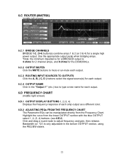
... screen) 6.D.1 OUTPUT DISPLAY BUTTONS 1, 2 (3, 4) Displays the frequency response of each amp output as a different color. 6.D.2 ADJUSTING PEQs FROM THE FREQUENCY CHART The Parametric EQs can be manipulated directly from the lower OUTPUT section with the blue OUTPUT select 1, 2, (3, 4) buttons. (see 6.E.2) Click and drag a round node to mute or un-mute each output. 6.C.3 ROUTING INPUT SOURCES TO OUTPUTS Click the A, B, ( C, D ) buttons select the signal source(s) for a single high power output. 6.C ROUTER (MATRIX) (middle left screen) 6.C.1 BRIDGE CHANNELS BRIDGE 1-2, (3-4) button...
... screen) 6.D.1 OUTPUT DISPLAY BUTTONS 1, 2 (3, 4) Displays the frequency response of each amp output as a different color. 6.D.2 ADJUSTING PEQs FROM THE FREQUENCY CHART The Parametric EQs can be manipulated directly from the lower OUTPUT section with the blue OUTPUT select 1, 2, (3, 4) buttons. (see 6.E.2) Click and drag a round node to mute or un-mute each output. 6.C.3 ROUTING INPUT SOURCES TO OUTPUTS Click the A, B, ( C, D ) buttons select the signal source(s) for a single high power output. 6.C ROUTER (MATRIX) (middle left screen) 6.C.1 BRIDGE CHANNELS BRIDGE 1-2, (3-4) button...
Instruction Manual
Page 23
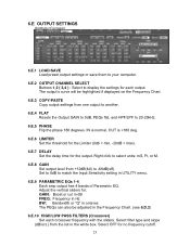
... degrees. 6.E OUTPUT SETTINGS (bottom of screen) 6.E.1 LOAD/SAVE Load preset output settings or save them to your computer. 6.E.2 OUTPUT CHANNEL SELECT Buttons 1,2 ( 3,4 ) : Select to match the Input Sensitivity setting in UTILITY menu. 6.E.9 PARAMETRIC EQs 1-4 Each amp output has 4 bands of Parametric EQ. IN is normal, OUT is +180 deg. 6.E.6 LIMITER Set the threshold for the Limiter (0db = min, -20dB = max). 6.E.7 DELAY Set the delay time for no frequency cutoff. 23 Adjust the vertical...
... degrees. 6.E OUTPUT SETTINGS (bottom of screen) 6.E.1 LOAD/SAVE Load preset output settings or save them to your computer. 6.E.2 OUTPUT CHANNEL SELECT Buttons 1,2 ( 3,4 ) : Select to match the Input Sensitivity setting in UTILITY menu. 6.E.9 PARAMETRIC EQs 1-4 Each amp output has 4 bands of Parametric EQ. IN is normal, OUT is +180 deg. 6.E.6 LIMITER Set the threshold for the Limiter (0db = min, -20dB = max). 6.E.7 DELAY Set the delay time for no frequency cutoff. 23 Adjust the vertical...

Instruction Manual
Page 26
models) Frequency Response: 20Hz-20kHz +/-1.5dB THD: 9. amps add 1/4" TRS IN and XLR THRU in parallel Maximum Input: +10dBu OUTPUTS: Output Connectors: 4-pin Twist-Lock (and binding posts on 2ch. SPECIFICATIONS INPUTS: XLR IN: 20kΩ balanced, ground lift switch 2ch.
models) Frequency Response: 20Hz-20kHz +/-1.5dB THD: 9. amps add 1/4" TRS IN and XLR THRU in parallel Maximum Input: +10dBu OUTPUTS: Output Connectors: 4-pin Twist-Lock (and binding posts on 2ch. SPECIFICATIONS INPUTS: XLR IN: 20kΩ balanced, ground lift switch 2ch.

