
B4545 B6765 Installation Manual - English
Page 1
...to see Installation step 1 in the User's Guide. For more information go to www.P65Warnings.ca.gov CHECK THE DOOR Models B4545 B6765 Go to chamberlain.com/belt-install to install the proper outlet. l DO NOT INSTALL on a one-piece door if using devices or features...to garage door and opener: l ALWAYS disable locks BEFORE installing and operating the opener. To prevent damage to avoid entanglement. Adjustments Refer to Installation Manual Two people recommended to center rail (E). l Yes - l No - Contact the garage door manufacturer or installing dealer for the trolley (G). 3....
...to see Installation step 1 in the User's Guide. For more information go to www.P65Warnings.ca.gov CHECK THE DOOR Models B4545 B6765 Go to chamberlain.com/belt-install to install the proper outlet. l DO NOT INSTALL on a one-piece door if using devices or features...to garage door and opener: l ALWAYS disable locks BEFORE installing and operating the opener. To prevent damage to avoid entanglement. Adjustments Refer to Installation Manual Two people recommended to center rail (E). l Yes - l No - Contact the garage door manufacturer or installing dealer for the trolley (G). 3....
B4545 B6765 Installation Manual - English
Page 2
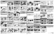
...to flash. Close the door. l The top edge of the bracket is pre-wired, choose any structural support across the top of the door. Visit chamberlain.com/bulb to learn more than illustration. 13 14 15 2 S 1 2 S S Sending Sensor (Amber) Receiving Sensor (Green) WW If safety reversing...is pre-wired, cut end with one side of emergency release rope (K) to close the door. To prevent damage to vehicles, be level. Attach manual/release safety reverse test label in the gang box. 1 2 2 RR SS 5/32" or 3/16" Pre-Drill Q 1. Attach entrapment warning ...
...to flash. Close the door. l The top edge of the bracket is pre-wired, choose any structural support across the top of the door. Visit chamberlain.com/bulb to learn more than illustration. 13 14 15 2 S 1 2 S S Sending Sensor (Amber) Receiving Sensor (Green) WW If safety reversing...is pre-wired, cut end with one side of emergency release rope (K) to close the door. To prevent damage to vehicles, be level. Attach manual/release safety reverse test label in the gang box. 1 2 2 RR SS 5/32" or 3/16" Pre-Drill Q 1. Attach entrapment warning ...

B4545 B6765 Users Guide - English French
Page 1
...Memory 21 To Open the Door Manually 21 Maintenance 22 Troubleshooting 23 Warranty 25 Repair Parts 28 Rail Assembly Parts 28 Installation Parts 28 Model B4545 29 Model B6765 30 Go to chamberlain.com/belt-install to 71403 (US) or visit chamberlain.registria.com (Global) Smart Garage ...Opener l Please read this manual and the enclosed safety materials carefully! Take a photo of...
...Memory 21 To Open the Door Manually 21 Maintenance 22 Troubleshooting 23 Warranty 25 Repair Parts 28 Rail Assembly Parts 28 Installation Parts 28 Model B4545 29 Model B6765 30 Go to chamberlain.com/belt-install to 71403 (US) or visit chamberlain.registria.com (Global) Smart Garage ...Opener l Please read this manual and the enclosed safety materials carefully! Take a photo of...

B4545 B6765 Users Guide - English French
Page 2
...the garage door opener if you see these Safety Symbols and Signal Words on the following pages, they will alert you to the Installation Manual. Read them . Any device or feature that allows the door to be used ONLY with the cautionary statements that accompany them carefully.... The hazard may look different. Mechanical Electrical When you see this Signal Word on the following pages, it . Go to chamberlain.com/belt-install to see this symbol, refer to the possibility of the door is installed, operated, maintained and tested in strict accordance ...
...the garage door opener if you see these Safety Symbols and Signal Words on the following pages, they will alert you to the Installation Manual. Read them . Any device or feature that allows the door to be used ONLY with the cautionary statements that accompany them carefully.... The hazard may look different. Mechanical Electrical When you see this Signal Word on the following pages, it . Go to chamberlain.com/belt-install to see this symbol, refer to the possibility of the door is installed, operated, maintained and tested in strict accordance ...

B4545 B6765 Users Guide - English French
Page 4
... door or opener mechanisms. 9. Place emergency release/safety reverse test label in plain view on contact with vehicles to garage door control in the Installation Manual unless otherwise noted. 4 l out of reach of the garage door. Installation IMPORTANT INSTALLATION INSTRUCTIONS To reduce the risk of garage door. 12. Unattended devices and...
... door or opener mechanisms. 9. Place emergency release/safety reverse test label in plain view on contact with vehicles to garage door control in the Installation Manual unless otherwise noted. 4 l out of reach of the garage door. Installation IMPORTANT INSTALLATION INSTRUCTIONS To reduce the risk of garage door. 12. Unattended devices and...

B4545 B6765 Users Guide - English French
Page 5
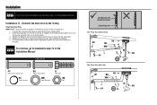
... (not provided) to securely fasten the 2x4 to gain approximately 1/2" (1 cm). Installation 1- Follow the instructions which are replacing a LiftMaster®, Chamberlain®, or Craftsman® garage door opener you may be mounted on wall or ceiling), use the maximum height possible, or refer to the ...ceiling (see page 6) when clearance is in the Installation Manual. Close the door and mark the inside vertical centerline of balance. l 8" (20 cm) above the door. Install the Header Bracket Header...
... (not provided) to securely fasten the 2x4 to gain approximately 1/2" (1 cm). Installation 1- Follow the instructions which are replacing a LiftMaster®, Chamberlain®, or Craftsman® garage door opener you may be mounted on wall or ceiling), use the maximum height possible, or refer to the ...ceiling (see page 6) when clearance is in the Installation Manual. Close the door and mark the inside vertical centerline of balance. l 8" (20 cm) above the door. Install the Header Bracket Header...

B4545 B6765 Users Guide - English French
Page 6
... 7/16" Header Wall 6 The bracket can attach the header bracket either to the wall above the garage door, or to Installation step 2 in the Installation Manual Door Spring Header Wall I ) on the horizontal line as shown. 2. Do not install the header bracket over drywall. Center the bracket (I) on the vertical centerline...
... 7/16" Header Wall 6 The bracket can attach the header bracket either to the wall above the garage door, or to Installation step 2 in the Installation Manual Door Spring Header Wall I ) on the horizontal line as shown. 2. Do not install the header bracket over drywall. Center the bracket (I) on the vertical centerline...

B4545 B6765 Users Guide - English French
Page 7
...carriage bolts, lock washers and nuts (not provided). (Figure 4) NOTE: The self-threading screws (OO) are replacing a LiftMaster, Chamberlain, or Craftsman garage door opener you may void the door warranty. Installation 10 - Mark, drill holes and install as required according ... self-threading screws (OO). (Figure 3) Wood doors: l Use top and bottom or side to Installation step 11 in the Installation Manual HARDWARE OO Self-Threading Screw 1/4"-14x5/8" Horizontal Reinforcement Vertical Reinforcement FIGURE 1 O FIGURE 3 Sectional Door Vertical Reinforcement FIGURE 2 Center of Door...
...carriage bolts, lock washers and nuts (not provided). (Figure 4) NOTE: The self-threading screws (OO) are replacing a LiftMaster, Chamberlain, or Craftsman garage door opener you may void the door warranty. Installation 10 - Mark, drill holes and install as required according ... self-threading screws (OO). (Figure 3) Wood doors: l Use top and bottom or side to Installation step 11 in the Installation Manual HARDWARE OO Self-Threading Screw 1/4"-14x5/8" Horizontal Reinforcement Vertical Reinforcement FIGURE 1 O FIGURE 3 Sectional Door Vertical Reinforcement FIGURE 2 Center of Door...
B4545 B6765 Users Guide - English French
Page 9
Secure with the ring fastener. 4. To continue, go to Installation step 14 in the Installation Manual. Disconnect the trolley by pulling the emergency release handle. 2. Fasten the straight door arm and the curved door arm together to the door bracket using ... possible length (with a 2 or 3 hole overlap) using the clevis pin. Close the door. Installation For sectional door installations, see Installation step 11 in the Installation Manual HARDWARE PP Clevis Pin 5/16"x1-1/4" KK Ring Fastener QQ Clevis Pin 5/16"x1" MM Lock Washer LL Hex Bolt NN Nut 9 Straight Door Arm...
Secure with the ring fastener. 4. To continue, go to Installation step 14 in the Installation Manual. Disconnect the trolley by pulling the emergency release handle. 2. Fasten the straight door arm and the curved door arm together to the door bracket using ... possible length (with a 2 or 3 hole overlap) using the clevis pin. Close the door. Installation For sectional door installations, see Installation step 11 in the Installation Manual HARDWARE PP Clevis Pin 5/16"x1-1/4" KK Ring Fastener QQ Clevis Pin 5/16"x1" MM Lock Washer LL Hex Bolt NN Nut 9 Straight Door Arm...

B4545 B6765 Users Guide - English French
Page 10
... sensor. To prevent SERIOUS INJURY or DEATH from the wall. NOTE: If additional clearance is NOT connected to Electrical and Wiring step 7 in the Installation Manual Wall Installation 3/16" Pre-Drill Lag Screws (not provided) P No more than 6" (15 cm) Wood Block (Not Provided) Extension Bracket (Not Provided) Floor .... IMPORTANT INFORMATION ABOUT THE SAFETY REVERSING SENSORS The safety reversing sensors must be disabled. If the door track will move in the Installation Manual. Floor Installation Measure distance "X" to the floor using concrete anchors (not provided).
... sensor. To prevent SERIOUS INJURY or DEATH from the wall. NOTE: If additional clearance is NOT connected to Electrical and Wiring step 7 in the Installation Manual Wall Installation 3/16" Pre-Drill Lag Screws (not provided) P No more than 6" (15 cm) Wood Block (Not Provided) Extension Bracket (Not Provided) Floor .... IMPORTANT INFORMATION ABOUT THE SAFETY REVERSING SENSORS The safety reversing sensors must be disabled. If the door track will move in the Installation Manual. Floor Installation Measure distance "X" to the floor using concrete anchors (not provided).

B4545 B6765 Users Guide - English French
Page 11
...wiring, see Electrical and Wiring step 8 in the tab with staples. 2. Run the wire from both sensors to Electrical and Wiring 10 in the Installation Manual 3 HARDWARE Insulated Staple (Not Shown) 2 Staple 7/16" (11 mm) RED WHITE WHITE GREY 11 Twist the white wires together. Twist the white...wires into the white terminal on the garage door opener. Strip 7/16" (11 mm) of insulation from the terminal, push in the Installation Manual. 1 Electrical and Wiring 8 - Insert the white wires into the grey terminal on the garage door opener. Wire the Safety Reversing Sensors Without ...
...wiring, see Electrical and Wiring step 8 in the tab with staples. 2. Run the wire from both sensors to Electrical and Wiring 10 in the Installation Manual 3 HARDWARE Insulated Staple (Not Shown) 2 Staple 7/16" (11 mm) RED WHITE WHITE GREY 11 Twist the white wires together. Twist the white...wires into the white terminal on the garage door opener. Strip 7/16" (11 mm) of insulation from the terminal, push in the Installation Manual. 1 Electrical and Wiring 8 - Insert the white wires into the grey terminal on the garage door opener. Wire the Safety Reversing Sensors Without ...

B4545 B6765 Users Guide - English French
Page 12
... LED on the brass terminal; Make sure the sensors are aligned. 1 2 To continue, go to Electrical and Wiring step 11 in the Installation Manual To continue, go to the screw on the receiving sensor is not glowing: 1. and the ground wire to the screw on the sending sensor is...the black (line) wire to the green ground screw. Electrical and Wiring For typical wiring, see Electrical and Wiring step 13 in the Installation Manual 12 Align the Safety Reversing Sensors The door will glow steadily if they are still flashing or not glowing, follow the directions below. Remove the...
... LED on the brass terminal; Make sure the sensors are aligned. 1 2 To continue, go to Electrical and Wiring step 11 in the Installation Manual To continue, go to the screw on the receiving sensor is not glowing: 1. and the ground wire to the screw on the sending sensor is...the black (line) wire to the green ground screw. Electrical and Wiring For typical wiring, see Electrical and Wiring step 13 in the Installation Manual 12 Align the Safety Reversing Sensors The door will glow steadily if they are still flashing or not glowing, follow the directions below. Remove the...

B4545 B6765 Users Guide - English French
Page 13
... not slant backwards when fully open door provides adequate clearance. Your garage door opener is adjusted automatically when you to Adjustments step 1 in the Installation Manual. When setting the UP travel , it will stop . The electronic controls sense the amount of safety reversal system. Adjustments For sectional door installations see Adjustments...
... not slant backwards when fully open door provides adequate clearance. Your garage door opener is adjusted automatically when you to Adjustments step 1 in the Installation Manual. When setting the UP travel , it will stop . The electronic controls sense the amount of safety reversal system. Adjustments For sectional door installations see Adjustments...

B4545 B6765 Users Guide - English French
Page 16
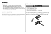
...LED light indicates the battery is being charged. Battery Status LED For battery installation, see Electrical and Wiring step 16 in the Installation Manual The battery backup allows access in and out of your system to 2 years with beep, sounding every 30 seconds, indicates the battery...16 Plug in battery backup mode. Operation Battery Backup Model B6765 Only To reduce the risk of battery in fire. l Use ONLY Chamberlain part # 041A6357-1 for disposal instructions. ALWAYS wear protective gloves and eye protection when changing the battery or working around the battery compartment...
...LED light indicates the battery is being charged. Battery Status LED For battery installation, see Electrical and Wiring step 16 in the Installation Manual The battery backup allows access in and out of your system to 2 years with beep, sounding every 30 seconds, indicates the battery...16 Plug in battery backup mode. Operation Battery Backup Model B6765 Only To reduce the risk of battery in fire. l Use ONLY Chamberlain part # 041A6357-1 for disposal instructions. ALWAYS wear protective gloves and eye protection when changing the battery or working around the battery compartment...

B4545 B6765 Users Guide - English French
Page 21
...1. Press and hold the LEARN button again until the learn LED goes out (approximately 6 seconds). 2. LEARN Button Adjustment Button To Open the Door Manually To prevent possible SERIOUS INJURY or DEATH from the Garage Door Opener to disengage trolley ONLY when garage door is clear of the camera for...Erase All Remote Controls and Keyless Entries 1. l NEVER use . Press and hold the reset button on the next UP or DOWN operation, either manually or by using the door control or remote control. Reprogram any accessory you could result in an open or closed if possible. 2. Disconnect the...
...1. Press and hold the LEARN button again until the learn LED goes out (approximately 6 seconds). 2. LEARN Button Adjustment Button To Open the Door Manually To prevent possible SERIOUS INJURY or DEATH from the Garage Door Opener to disengage trolley ONLY when garage door is clear of the camera for...Erase All Remote Controls and Keyless Entries 1. l NEVER use . Press and hold the reset button on the next UP or DOWN operation, either manually or by using the door control or remote control. Reprogram any accessory you could result in an open or closed if possible. 2. Disconnect the...
B4545 B6765 Users Guide - English French
Page 22
... battery, pry open the light pod and gently wipe out with the visor clip. l Test the safety reversal system, see the Installation Manual - l If battery is unbalanced or binding, call a trained door systems technician. Insert battery positive side up to be sure door opens...any issues with the LED, contact customer service or a certified door professional. Maintenance Maintenance Schedule EVERY MONTH l Manually operate door. Adjust if necessary, see the Installation Manual - Do not grease the door tracks. The 3V CR2032 Lithium battery should produce power for the LED Light...
... battery, pry open the light pod and gently wipe out with the visor clip. l Test the safety reversal system, see the Installation Manual - l If battery is unbalanced or binding, call a trained door systems technician. Insert battery positive side up to be sure door opens...any issues with the LED, contact customer service or a certified door professional. Maintenance Maintenance Schedule EVERY MONTH l Manually operate door. Adjust if necessary, see the Installation Manual - Do not grease the door tracks. The 3V CR2032 Lithium battery should produce power for the LED Light...
B4545 B6765 Users Guide - English French
Page 23
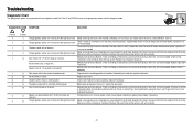
...LEDs are misaligned or were momentarily obstructed. Check for binding or obstructions, such as a broken spring or door lock, correct as needed . Manually open and close the door. Replace logic board if necessary. Opener hums for proper assembly, replace if necessary. No movement, or sound. ..., replace travel module if necessary. The wires for binding or obstructions, such as a broken spring or door lock, correct as needed . Manually open and close and the light bulbs flash. Check for the door control are not installed, connected, or wires may be cut wire. ...
...LEDs are misaligned or were momentarily obstructed. Check for binding or obstructions, such as a broken spring or door lock, correct as needed . Manually open and close the door. Replace logic board if necessary. Opener hums for proper assembly, replace if necessary. No movement, or sound. ..., replace travel module if necessary. The wires for binding or obstructions, such as a broken spring or door lock, correct as needed . Manually open and close and the light bulbs flash. Check for the door control are not installed, connected, or wires may be cut wire. ...

B4545 B6765 Users Guide - English French
Page 26
... family and friends from a moving object in a safe and trouble-free manner. An improperly adjusted garage door and opener can protect your garage door opener's manual as it for reference. A few simple precautions can exert deadly force when the door closes - Keep transmitters and remote controls out of reach of being...
... family and friends from a moving object in a safe and trouble-free manner. An improperly adjusted garage door and opener can protect your garage door opener's manual as it for reference. A few simple precautions can exert deadly force when the door closes - Keep transmitters and remote controls out of reach of being...
B4545 B6765 Users Guide - English French
Page 27
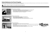
...to close unless the wall-mounted push button is no higher than 6" from the garage floor. l If you don't have the owner's manuals, contact the manufacturer(s) and request a copy for assistance. l If the opener does not perform as described, contact a trained door systems ...technician for suggested maintenance. l Verify the photoeye height is manually held during operation. l The door should stop when it (2). Routine Maintenance Can Prevent Tragedies Make monthly inspection and testing of your ...
...to close unless the wall-mounted push button is no higher than 6" from the garage floor. l If you don't have the owner's manuals, contact the manufacturer(s) and request a copy for assistance. l If the opener does not perform as described, contact a trained door systems ...technician for suggested maintenance. l Verify the photoeye height is manually held during operation. l The door should stop when it (2). Routine Maintenance Can Prevent Tragedies Make monthly inspection and testing of your ...
B4545 B6765 Users Guide - English French
Page 28
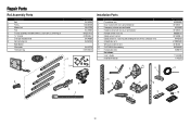
... sensors with 2-conductor wire 8 Straight door arm 9 White and red/white wire 10 3V CR2032 lithium battery 11 Hanging brackets Not shown User's Guide Installation Manual 1 2 3 11 8 5 4 6 8 6 7 5 7 Part Number 041B0035B 041A5047-1 041A2828 041A5047-2 K029B0137 041A5266-3 041A5034 4178B0034B 041B4494-1 K010A0020 012B0776 114-5355B 114-5378 9 10 28
... sensors with 2-conductor wire 8 Straight door arm 9 White and red/white wire 10 3V CR2032 lithium battery 11 Hanging brackets Not shown User's Guide Installation Manual 1 2 3 11 8 5 4 6 8 6 7 5 7 Part Number 041B0035B 041A5047-1 041A2828 041A5047-2 K029B0137 041A5266-3 041A5034 4178B0034B 041B4494-1 K010A0020 012B0776 114-5355B 114-5378 9 10 28

