HD950WF Owners Manual Manual
Page 1
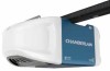
... with MyQ® Smartphone Control and Battery Backup Models • WD1000WF • HD950WF • LW9000WF FOR RESIDENTIAL USE ONLY ■ Please read this garage door opener system meets Chamberlain's pulling force specification for a 1-1/4 horsepower garage door opener. CONTENTS Preparation 1-4 Assembly 5-8 Installation 9-26 Adjustments 27-29 Battery Backup 30 MyQ® Smartphone Control Get...
... with MyQ® Smartphone Control and Battery Backup Models • WD1000WF • HD950WF • LW9000WF FOR RESIDENTIAL USE ONLY ■ Please read this garage door opener system meets Chamberlain's pulling force specification for a 1-1/4 horsepower garage door opener. CONTENTS Preparation 1-4 Assembly 5-8 Installation 9-26 Adjustments 27-29 Battery Backup 30 MyQ® Smartphone Control Get...
HD950WF Owners Manual Manual
Page 2
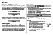
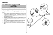
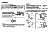
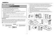
... Preparation Safety Symbol and Signal Word Review This garage door opener has been designed and tested to offer safe service provided it is installed, operated, maintained and tested in strict accordance with the instructions and warnings contained in the line of sight of the door is ...technician if garage door binds, sticks, or is an example of the door. Read the warnings carefully. The hazard may be installed within 4 feet (1.2 m) to be installed above the center of the door must not exceed 1/4 inch (6 mm). Any device or feature that accompany it should be ...
... Preparation Safety Symbol and Signal Word Review This garage door opener has been designed and tested to offer safe service provided it is installed, operated, maintained and tested in strict accordance with the instructions and warnings contained in the line of sight of the door is ...technician if garage door binds, sticks, or is an example of the door. Read the warnings carefully. The hazard may be installed within 4 feet (1.2 m) to be installed above the center of the door must not exceed 1/4 inch (6 mm). Any device or feature that accompany it should be ...

HD950WF Owners Manual Manual
Page 3
...mobile device in the place where your garage door opener will need a router with Wi-Fi and a smartphone or other objects • Buy a Chamberlain MyQ® Internet Gateway (CIGBU) see : Wi-Fi signal is weak. l Extension brackets (MODEL 041A5281-1) or wood blocks: Depending upon garage ...construction, extension brackets or wood blocks may be installed and check the Wi-Fi signal strength. The garage door opener will need any of wood : May be used to fasten the header bracket...
...mobile device in the place where your garage door opener will need a router with Wi-Fi and a smartphone or other objects • Buy a Chamberlain MyQ® Internet Gateway (CIGBU) see : Wi-Fi signal is weak. l Extension brackets (MODEL 041A5281-1) or wood blocks: Depending upon garage ...construction, extension brackets or wood blocks may be installed and check the Wi-Fi signal strength. The garage door opener will need any of wood : May be used to fasten the header bracket...

HD950WF Owners Manual Manual
Page 4
... Sensor (1), Receiving Sensor (1), and Safety Sensor Brackets (2) NOT SHOWN White and red/white wire Owner's manual Hardware 3 Save the carton and packing material until the installation and adjustment is packaged in this manual are not included in one carton which contains the motor unit and all parts illustrated below. Accessories vary...
... Sensor (1), Receiving Sensor (1), and Safety Sensor Brackets (2) NOT SHOWN White and red/white wire Owner's manual Hardware 3 Save the carton and packing material until the installation and adjustment is packaged in this manual are not included in one carton which contains the motor unit and all parts illustrated below. Accessories vary...
HD950WF Owners Manual Manual
Page 5
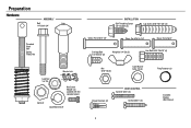
Preparation Hardware ASSEMBLY Bolt Bolt 1/4"-20x1-3/4" INSTALLATION Self-Threading Screw 1/4"-14x5/8" (2) Lag Screw 5/16"-9x1-5/8" (4) Threaded Shaft with Spring Trolley Nut Clevis Pin 5/16"x1-1/2" Clevis Pin 5/16"x1-1/4" Clevis Pin 5/16"...
Preparation Hardware ASSEMBLY Bolt Bolt 1/4"-20x1-3/4" INSTALLATION Self-Threading Screw 1/4"-14x5/8" (2) Lag Screw 5/16"-9x1-5/8" (4) Threaded Shaft with Spring Trolley Nut Clevis Pin 5/16"x1-1/2" Clevis Pin 5/16"x1-1/4" Clevis Pin 5/16"...
HD950WF Owners Manual Manual
Page 6
...assembly toward the screwdriver as shown. 6. Place the motor unit on the top and sides of the rail. 4. Assembly STEP 1 Assemble the rail and install the trolley To prevent INJURY from pinching, keep hands and fingers away from the motor unit, as shown and slide the tapered ends into the... larger ones. Outer Trolley To avoid installation difficulties, do so. If they became loose during shipping, check all the stops on packing material to do not run the garage door opener ...
...assembly toward the screwdriver as shown. 6. Place the motor unit on the top and sides of the rail. 4. Assembly STEP 1 Assemble the rail and install the trolley To prevent INJURY from pinching, keep hands and fingers away from the motor unit, as shown and slide the tapered ends into the... larger ones. Outer Trolley To avoid installation difficulties, do so. If they became loose during shipping, check all the stops on packing material to do not run the garage door opener ...

HD950WF Owners Manual Manual
Page 7
... avoid SERIOUS damage to ensure proper operation. 3. Insert a 1/4"-20x1-3/4" bolt into the window as shown. 4. DO NOT use of the rail as shown. HARDWARE STEP 3 Install the idler pulley 1. Lay the belt beside the rail, as shown. The inside center should be sure it to support the front end of the...
... avoid SERIOUS damage to ensure proper operation. 3. Insert a 1/4"-20x1-3/4" bolt into the window as shown. 4. DO NOT use of the rail as shown. HARDWARE STEP 3 Install the idler pulley 1. Lay the belt beside the rail, as shown. The inside center should be sure it to support the front end of the...
HD950WF Owners Manual Manual
Page 8
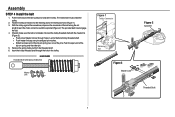
... 1). 3. Connect the trolley threaded shaft with Spring Trolley Nut Master Link Figure 1 Trolley Connector Retaining Slot Figure 3 Master Link Figure 2 Sprocket Threaded Shaft 7 Assembly STEP 4 Install the belt 1. Hook the trolley connector into the retaining slot on spring onto the other pin. 5. Check to make sure the belt is not twisted...
... 1). 3. Connect the trolley threaded shaft with Spring Trolley Nut Master Link Figure 1 Trolley Connector Retaining Slot Figure 3 Master Link Figure 2 Sprocket Threaded Shaft 7 Assembly STEP 4 Install the belt 1. Hook the trolley connector into the retaining slot on spring onto the other pin. 5. Check to make sure the belt is not twisted...
HD950WF Owners Manual Manual
Page 9
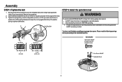
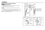
... Nut Ring HARDWARE Hex Screw #8x3/8" (Packed with 8x3/8" hex screws provided. Remove the screwdriver. 2. Spring Trolley Nut Nut Ring Slot STEP 6 Install the sprocket cover To avoid possible SERIOUS INJURY to the mounting plate with the sprocket cover) BEFORE 1" (2.5 cm) AFTER 1-1/4" (3.18 cm) Hex ...Screw #8x3/8" Sprocket Cover 8 Assembly STEP 5 Tighten the belt 1. Do not use any tools. This sets the spring to the installation section. Position the sprocket cover over the sprocket as shown and fasten to finger from moving garage door opener: l ALWAYS keep hand clear of ...
... Nut Ring HARDWARE Hex Screw #8x3/8" (Packed with 8x3/8" hex screws provided. Remove the screwdriver. 2. Spring Trolley Nut Nut Ring Slot STEP 6 Install the sprocket cover To avoid possible SERIOUS INJURY to the mounting plate with the sprocket cover) BEFORE 1" (2.5 cm) AFTER 1-1/4" (3.18 cm) Hex ...Screw #8x3/8" Sprocket Cover 8 Assembly STEP 5 Tighten the belt 1. Do not use any tools. This sets the spring to the installation section. Position the sprocket cover over the sprocket as shown and fasten to finger from moving garage door opener: l ALWAYS keep hand clear of ...

HD950WF Owners Manual Manual
Page 10
... balanced door may NOT reverse when required and could be made by a trained door systems technician BEFORE installing opener. 4. They could result in garage door or opener mechanisms. 9. Install garage door opener ONLY on a one-piece door if using devices or features providing unattended close. ALL...test label in plain view on contact with sectional doors. 9 Upon completion of garage door. 12. Door MUST reverse on inside of installation, test safety reversal system. Mount the emergency release within sight of SEVERE INJURY or DEATH: 1. NEVER connect garage door opener to ...
... balanced door may NOT reverse when required and could be made by a trained door systems technician BEFORE installing opener. 4. They could result in garage door or opener mechanisms. 9. Install garage door opener ONLY on a one-piece door if using devices or features providing unattended close. ALL...test label in plain view on contact with sectional doors. 9 Upon completion of garage door. 12. Door MUST reverse on inside of installation, test safety reversal system. Mount the emergency release within sight of SEVERE INJURY or DEATH: 1. NEVER connect garage door opener to ...
HD950WF Owners Manual Manual
Page 11
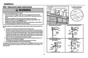
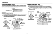
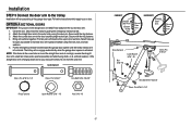
... of travel clearance for one -piece door with horizontal track Header Wall 2" (5 cm) Door Track Highest Point of Travel Pivot Installation procedures vary according to structural supports as shown. Extend the line onto the header wall above the door.You can attach it to..., springs, cables, pulleys, brackets, or their hardware, ALL of the door. l 8" (20 cm) above the high point for ceiling installation. 10 Header Wall Vertical Centerline of Garage Door 2x4 Structural Supports OPTIONAL CEILING MOUNT FOR HEADER BRACKET Unfinished Ceiling Level (Optional) Sectional ...
... of travel clearance for one -piece door with horizontal track Header Wall 2" (5 cm) Door Track Highest Point of Travel Pivot Installation procedures vary according to structural supports as shown. Extend the line onto the header wall above the door.You can attach it to..., springs, cables, pulleys, brackets, or their hardware, ALL of the door. l 8" (20 cm) above the high point for ceiling installation. 10 Header Wall Vertical Centerline of Garage Door 2x4 Structural Supports OPTIONAL CEILING MOUNT FOR HEADER BRACKET Unfinished Ceiling Level (Optional) Sectional ...
HD950WF Owners Manual Manual
Page 12
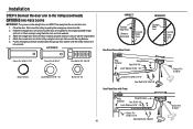
... the vertical centerline onto the ceiling as shown (with the hardware provided. Center the bracket on the horizontal line as shown. 2. If installing into masonry, use concrete anchors (not provided). Center the bracket on the vertical centerline with the bottom edge of Garage Door Travel Door ... mark, no more than 6" (15 cm) from the wall. Follow the instructions which will work best for your particular requirements. Installation STEP 2 Install the header bracket You can be mounted flush against the ceiling when clearance is pointing away from the wall. Drill 3/16" pilot ...
... the vertical centerline onto the ceiling as shown (with the hardware provided. Center the bracket on the horizontal line as shown. 2. If installing into masonry, use concrete anchors (not provided). Center the bracket on the vertical centerline with the bottom edge of Garage Door Travel Door ... mark, no more than 6" (15 cm) from the wall. Follow the instructions which will work best for your particular requirements. Installation STEP 2 Install the header bracket You can be mounted flush against the ceiling when clearance is pointing away from the wall. Drill 3/16" pilot ...
HD950WF Owners Manual Manual
Page 13
... the header bracket. 3. Connected Disconnected All other door types One-piece door without tracks, lay the 2x4 on the garage floor below the header bracket. Installation STEP 3 Attach the rail to disconnect the inner and outer trolley. Position the opener on it is not tall enough you will need help at...
... the header bracket. 3. Connected Disconnected All other door types One-piece door without tracks, lay the 2x4 on the garage floor below the header bracket. Installation STEP 3 Attach the rail to disconnect the inner and outer trolley. Position the opener on it is not tall enough you will need help at...
HD950WF Owners Manual Manual
Page 14
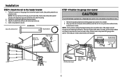
...provided). 5. The instructions illustrate one of the hanging bracket to required lengths. 4. Concrete anchors MUST be different. Below are three example installations. Make sure the garage door opener is aligned with the header bracket. If the door hits the rail, raise the header bracket. ...(not provided) to the support bracket. 3. Measure the distance from a falling garage door opener, fasten it SECURELY to structural supports. Installation STEP 5 Hang the garage door opener To avoid possible SERIOUS INJURY from each hanging bracket to the hanging brackets with the hex bolts...
...provided). 5. The instructions illustrate one of the hanging bracket to required lengths. 4. Concrete anchors MUST be different. Below are three example installations. Make sure the garage door opener is aligned with the header bracket. If the door hits the rail, raise the header bracket. ...(not provided) to the support bracket. 3. Measure the distance from a falling garage door opener, fasten it SECURELY to structural supports. Installation STEP 5 Hang the garage door opener To avoid possible SERIOUS INJURY from each hanging bracket to the hanging brackets with the hex bolts...
HD950WF Owners Manual Manual
Page 15
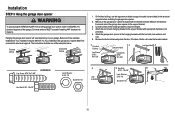
... fluorescent light bulbs larger than 100W. Tie a knot at least 6 feet (1.83 m) above the top of the emergency release rope. 2. l DO NOT use halogen bulbs. Installation STEP 6 Install the light bulbs STEP 7 Attach the emergency release rope and handle To prevent possible OVERHEATING of your remote controls.
... fluorescent light bulbs larger than 100W. Tie a knot at least 6 feet (1.83 m) above the top of the emergency release rope. 2. l DO NOT use halogen bulbs. Installation STEP 6 Install the light bulbs STEP 7 Attach the emergency release rope and handle To prevent possible OVERHEATING of your remote controls.
HD950WF Owners Manual Manual
Page 16
... reinforcement brace should be long enough to be secured to side door bracket holes. Contact the garage door manufacturer or installing dealer for direct attachment of door bracket. A horizontal and vertical reinforcement is needed for opener reinforcement instructions or reinforcement ...section as stamped inside the bracket. 2. proceed to the door manufacturer may void the door warranty. Contact the garage door manufacturer or installing dealer for lightweight garage doors (fiberglass, aluminum, steel, doors with 5/16"-18x2" carriage bolts, lock washers and nuts (not provided...
... reinforcement brace should be long enough to be secured to side door bracket holes. Contact the garage door manufacturer or installing dealer for direct attachment of door bracket. A horizontal and vertical reinforcement is needed for opener reinforcement instructions or reinforcement ...section as stamped inside the bracket. 2. proceed to the door manufacturer may void the door warranty. Contact the garage door manufacturer or installing dealer for lightweight garage doors (fiberglass, aluminum, steel, doors with 5/16"-18x2" carriage bolts, lock washers and nuts (not provided...
HD950WF Owners Manual Manual
Page 17
... Optional Placement Hardware (not provided) Top of Door (Inside Garage) Top Edge of Garage Door For a door with no exposed framing, or for your installation needs. Mark either the left and right, or the top and bottom holes. Wood Doors: l Drill 5/16" holes and use 5/16"-18x2" carriage... door, in line with the self-threading screws provided. Center the door bracket on the top edge of the door if required for the optional installation, use lag screws 5/16"x1-1/2" (not provided) to the dotted line optional placement drawing.) Header Wall 2x4 Support Header Bracket (Finished Ceiling)...
... Optional Placement Hardware (not provided) Top of Door (Inside Garage) Top Edge of Garage Door For a door with no exposed framing, or for your installation needs. Mark either the left and right, or the top and bottom holes. Wood Doors: l Drill 5/16" holes and use 5/16"-18x2" carriage... door, in line with the self-threading screws provided. Center the door bracket on the top edge of the door if required for the optional installation, use lag screws 5/16"x1-1/2" (not provided) to the dotted line optional placement drawing.) Header Wall 2x4 Support Header Bracket (Finished Ceiling)...
HD950WF Owners Manual Manual
Page 18
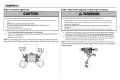
... the door arm to the trolley Installation will re-engage automatically when the garage door opener is activated. Bring arm sections together. Find two pairs of holes that line up and join ...
... the door arm to the trolley Installation will re-engage automatically when the garage door opener is activated. Bring arm sections together. Find two pairs of holes that line up and join ...
HD950WF Owners Manual Manual
Page 19
... the emergency release handle toward the garage door opener until the trolley release arm is horizontal. Secure with a 2 or 3 hole overlap) using the clevis pin. Installation STEP 9 Connect the door arm to the door bracket using the clevis pin.
... the emergency release handle toward the garage door opener until the trolley release arm is horizontal. Secure with a 2 or 3 hole overlap) using the clevis pin. Installation STEP 9 Connect the door arm to the door bracket using the clevis pin.
HD950WF Owners Manual Manual
Page 20
...a later step. 3. INTRODUCTION Older Chamberlain door controls and third party products are no obstructions to drill holes or install the drywall anchors. Connect one end of the wire and separate the wires. 2. If your garage is NOT connected BEFORE installing door control. Mark the location of...of the door control over the screw and slide down into place. Screw 6-32x1" (2) Drywall Anchors (2) HARDWARE Screw 6ABx1" (2) 1. Installation STEP 10 Install the door control To prevent possible SERIOUS INJURY or DEATH from the wall. 5. Position the bottom hole of the door. l Connect ...
...a later step. 3. INTRODUCTION Older Chamberlain door controls and third party products are no obstructions to drill holes or install the drywall anchors. Connect one end of the wire and separate the wires. 2. If your garage is NOT connected BEFORE installing door control. Mark the location of...of the door control over the screw and slide down into place. Screw 6-32x1" (2) Drywall Anchors (2) HARDWARE Screw 6ABx1" (2) 1. Installation STEP 10 Install the door control To prevent possible SERIOUS INJURY or DEATH from the wall. 5. Position the bottom hole of the door. l Connect ...
