

Installation Guide
Page 5
... Switch Software Features 1-4 Hardware System Features 1-6 Switch Components 1-7 Traffic Ports on the Catalyst 4948 1-7 Traffic Ports on the Catalyst 4948-10GE 1-7 Traffic Ports on the Catalyst 4928-10GE 1-7 Console Port 1-7 Front Panel LEDs 1-9 Chassis Cooling 1-11 Power Supplies 1-12 Environmental Monitoring of the Power Supplies 1-13 Power Management for the Switch 1-14 Power Management Modes 1-14 Site Planning 2-1 Site Environmental Requirements 2-1 Site Power Requirements 2-2 Pre-installation Requirements 2-3 Warnings and Cautions 2-3 78-18039-02 Catalyst 4900 Series Switch Installation...
... Switch Software Features 1-4 Hardware System Features 1-6 Switch Components 1-7 Traffic Ports on the Catalyst 4948 1-7 Traffic Ports on the Catalyst 4948-10GE 1-7 Traffic Ports on the Catalyst 4928-10GE 1-7 Console Port 1-7 Front Panel LEDs 1-9 Chassis Cooling 1-11 Power Supplies 1-12 Environmental Monitoring of the Power Supplies 1-13 Power Management for the Switch 1-14 Power Management Modes 1-14 Site Planning 2-1 Site Environmental Requirements 2-1 Site Power Requirements 2-2 Pre-installation Requirements 2-3 Warnings and Cautions 2-3 78-18039-02 Catalyst 4900 Series Switch Installation...

Installation Guide
Page 6
...Tools 3-5 Rack-Mounting the Switch 3-6 Connecting AC Power to the Switch 3-9 Connecting DC Power to the Switch 3-11 Transceiver Modules 4-1 SFP Modules 4-1 SFP Modules and Alternative Wiring 4-1 X2 Modules 4-2 Module Maintenance Guidelines 4-5 Cleaning the Fiber-Optic Connectors 4-5 Additional Guidelines 4-7 Troubleshooting the Installation 5-1 Getting Started 5-2 Problem Solving to the System Component Level 5-2 Identifying Startup Problems 5-3 LED Readings 5-3 Troubleshooting the Power Supply 5-5 Contacting Customer Service 5-6 Specifications A-1 Console Port A-1 Catalyst 4900 Series Switch...
...Tools 3-5 Rack-Mounting the Switch 3-6 Connecting AC Power to the Switch 3-9 Connecting DC Power to the Switch 3-11 Transceiver Modules 4-1 SFP Modules 4-1 SFP Modules and Alternative Wiring 4-1 X2 Modules 4-2 Module Maintenance Guidelines 4-5 Cleaning the Fiber-Optic Connectors 4-5 Additional Guidelines 4-7 Troubleshooting the Installation 5-1 Getting Started 5-2 Problem Solving to the System Component Level 5-2 Identifying Startup Problems 5-3 LED Readings 5-3 Troubleshooting the Power Supply 5-5 Contacting Customer Service 5-6 Specifications A-1 Console Port A-1 Catalyst 4900 Series Switch...

Installation Guide
Page 7
... P E N D I X Management Port A-2 Catalyst 4900 Series Switch Specifications A-3 Initial Configuration for the Switch B-1 Connecting to the Switch B-2 Starting the Terminal-Emulation Software B-3 Connecting to a Power Source B-3 Entering the Initial Configuration Information B-4 IP Settings B-4 Performing the Initial Configuration B-5 Compliance Information and Translated Safety Warnings C-1 Translated Safety Warnings C-2 Statement 1003-DC Power Disconnection C-2 Statement 1004-Installation Instructions C-4 Statement 1006-Chassis Warning for Rack-Mounting and Servicing C-6 Statement 1008-Class...
... P E N D I X Management Port A-2 Catalyst 4900 Series Switch Specifications A-3 Initial Configuration for the Switch B-1 Connecting to the Switch B-2 Starting the Terminal-Emulation Software B-3 Connecting to a Power Source B-3 Entering the Initial Configuration Information B-4 IP Settings B-4 Performing the Initial Configuration B-5 Compliance Information and Translated Safety Warnings C-1 Translated Safety Warnings C-2 Statement 1003-DC Power Disconnection C-2 Statement 1004-Installation Instructions C-4 Statement 1006-Chassis Warning for Rack-Mounting and Servicing C-6 Statement 1008-Class...
Installation Guide
Page 10
... for the Switch configuration via Telnet. Related Documentation The Catalyst 4900 series switches use software that will allow further for the switches and repeats in multiple languages the warnings in this guide. Initial Configuration Details initial setup of these documents appropriate for your software release: • Catalyst 4500 Series Switch Cisco IOS Software Configuration Guide http://www.cisco.com/en/US/products/hw/switches/ps4324/products_install ation_and_configuration_guides_list.html • Catalyst 4500 Series Switch Cisco IOS Command Reference http://www.cisco.com/en...
... for the Switch configuration via Telnet. Related Documentation The Catalyst 4900 series switches use software that will allow further for the switches and repeats in multiple languages the warnings in this guide. Initial Configuration Details initial setup of these documents appropriate for your software release: • Catalyst 4500 Series Switch Cisco IOS Software Configuration Guide http://www.cisco.com/en/US/products/hw/switches/ps4324/products_install ation_and_configuration_guides_list.html • Catalyst 4500 Series Switch Cisco IOS Command Reference http://www.cisco.com/en...

Installation Guide
Page 24
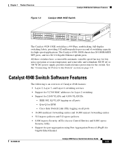
..., full-duplex switching fabric, providing 72 million packets-per -second of switching capacity for high-speed applications. Catalyst 4900 Series Switch Applications Chapter 1 Product Overview Catalyst 4900 Series Switch Applications The Catalyst 4900 series switches (see Figure 1-1, Figure 1-2, and Figure 1-3) are fixed configuration switching solutions delivering 10/100/1000 connectivity on all ports, supporting hot swappable, redundant power supplies in a compact one rack-unit size for applications where space is limited. Catalyst 4900 Series Switch Installation Guide 1-2 78...
..., full-duplex switching fabric, providing 72 million packets-per -second of switching capacity for high-speed applications. Catalyst 4900 Series Switch Applications Chapter 1 Product Overview Catalyst 4900 Series Switch Applications The Catalyst 4900 series switches (see Figure 1-1, Figure 1-2, and Figure 1-3) are fixed configuration switching solutions delivering 10/100/1000 connectivity on all ports, supporting hot swappable, redundant power supplies in a compact one rack-unit size for applications where space is limited. Catalyst 4900 Series Switch Installation Guide 1-2 78...
Installation Guide
Page 25
... VLANs and 4,096 VLAN IDs - See the "Connecting AC Power to the Switch" section on all ports - Q-in-Q for Gigabit EtherChannel 78-18039-02 Catalyst 4900 Series Switch Installation Guide 1-3 Cisco Inter Switch Link (ISL) tagging on page 3-9. The Catalyst 4928-10GE chassis has 28 1000BASEX SFP ports, and two X2 10-Gigabit Ethernet uplink ports. Chapter 1 Product Overview Catalyst 4948 Switch Software Features Figure 1-3 Catalyst 4928-10GE Switch 271710 PS1 PS2 FAN STATUS 1 8 9 16 17 CON MGMT 24 25 26 ENABLED 27...
... VLANs and 4,096 VLAN IDs - See the "Connecting AC Power to the Switch" section on all ports - Q-in-Q for Gigabit EtherChannel 78-18039-02 Catalyst 4900 Series Switch Installation Guide 1-3 Cisco Inter Switch Link (ISL) tagging on page 3-9. The Catalyst 4928-10GE chassis has 28 1000BASEX SFP ports, and two X2 10-Gigabit Ethernet uplink ports. Chapter 1 Product Overview Catalyst 4948 Switch Software Features Figure 1-3 Catalyst 4928-10GE Switch 271710 PS1 PS2 FAN STATUS 1 8 9 16 17 CON MGMT 24 25 26 ENABLED 27...
Installation Guide
Page 26
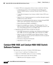
... MIBs, and all ports Catalyst 4900 Series Switch Installation Guide 1-4 78-18039-02 Support for standard Layer 2 features: 802.1D Spanning Tree, Cisco Discovery Protocol (CDP), VTP version 2 with the Catalyst 4500 series switches - Support for 4,096 VLANs and 4,096 VLAN IDs - Command-line interface (CLI) and Simple Network Management Protocol (SNMP) interfaces consistent with RMON-1 - Performance management information - Remote Monitoring (RMON) with the Catalyst 4500 series switches - Support for in-band management through any switch port through a terminal attached to the...
... MIBs, and all ports Catalyst 4900 Series Switch Installation Guide 1-4 78-18039-02 Support for standard Layer 2 features: 802.1D Spanning Tree, Cisco Discovery Protocol (CDP), VTP version 2 with the Catalyst 4500 series switches - Support for 4,096 VLANs and 4,096 VLAN IDs - Command-line interface (CLI) and Simple Network Management Protocol (SNMP) interfaces consistent with RMON-1 - Performance management information - Remote Monitoring (RMON) with the Catalyst 4500 series switches - Support for in-band management through any switch port through a terminal attached to the...

Installation Guide
Page 27
...) on all relevant Cisco MIBs - Embedded CiscoView support 78-18039-02 Catalyst 4900 Series Switch Installation Guide 1-5 Cisco Inter Switch Link (ISL) tagging on a per-port basis without the need for standard Layer 2 features: 802.1D Spanning Tree, Cisco Discovery Protocol (CDP), VTP version 2 with the Catalyst 4500 series switches - Compatible development of -band management over serial lines through SNMP, Telnet client, and Trivial File Transfer Protocol (TFTP) - Support for Gigabit EtherChannel • Catalyst 4500 series management software features include the following...
...) on all relevant Cisco MIBs - Embedded CiscoView support 78-18039-02 Catalyst 4900 Series Switch Installation Guide 1-5 Cisco Inter Switch Link (ISL) tagging on a per-port basis without the need for standard Layer 2 features: 802.1D Spanning Tree, Cisco Discovery Protocol (CDP), VTP version 2 with the Catalyst 4500 series switches - Compatible development of -band management over serial lines through SNMP, Telnet client, and Trivial File Transfer Protocol (TFTP) - Support for Gigabit EtherChannel • Catalyst 4500 series management software features include the following...
Installation Guide
Page 28
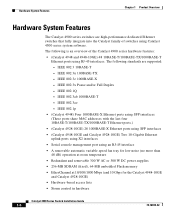
... and/or Full Duplex - IEEE 802.1Q - The following is an overview of switches using Catalyst 4500 series system software. IEEE 802.3ae - IEEE 802.1p • (Catalyst 4948) Four 1000BASE-X Ethernet ports using SFP interfaces (These ports share MAC addresses with the last four 10BASE-T/100BASE-TX/1000BASE-T Ethernet ports.) • (Catalyst 4928-10GE) 28 1000BASE-X Ethernet ports using SFP interfaces • (Catalyst 4948-10GE and Catalyst 4928-10GE) Two 10-Gigabit Ethernet uplink ports using X2 interfaces • Serial console management port using RJ-45 interfaces. IEEE 802...
... and/or Full Duplex - IEEE 802.1Q - The following is an overview of switches using Catalyst 4500 series system software. IEEE 802.3ae - IEEE 802.1p • (Catalyst 4948) Four 1000BASE-X Ethernet ports using SFP interfaces (These ports share MAC addresses with the last four 10BASE-T/100BASE-TX/1000BASE-T Ethernet ports.) • (Catalyst 4928-10GE) 28 1000BASE-X Ethernet ports using SFP interfaces • (Catalyst 4948-10GE and Catalyst 4928-10GE) Two 10-Gigabit Ethernet uplink ports using X2 interfaces • Serial console management port using RJ-45 interfaces. IEEE 802...
Installation Guide
Page 29
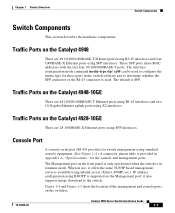
... management and console ports on the Catalyst 4948 There are 48 10/100/1000BASE-T Ethernet ports using RJ-45 interfaces and two 10-Gigabit Ethernet uplink ports using inband access (Telnet, SNMP, etc.). The interface configuration mode command media-type sfp | rj45 can be used . Chapter 1 Product Overview Switch Components Switch Components This section describes the hardware components. These SFP ports share MAC addresses with the last four 10/100/1000BASE-T ports. Traffic Ports on the front panel is only operational when the switch is in the switch software...
... management and console ports on the Catalyst 4948 There are 48 10/100/1000BASE-T Ethernet ports using RJ-45 interfaces and two 10-Gigabit Ethernet uplink ports using inband access (Telnet, SNMP, etc.). The interface configuration mode command media-type sfp | rj45 can be used . Chapter 1 Product Overview Switch Components Switch Components This section describes the hardware components. These SFP ports share MAC addresses with the last four 10/100/1000BASE-T ports. Traffic Ports on the front panel is only operational when the switch is in the switch software...

Installation Guide
Page 32
... states for this port 10/100 BASE-T Management port is in link-up state 10/100 BASE-T Management port is in link-down state or not connected There are no blinking, red, or yellow states for this port Port is operational Port is disabled by user Power-on self-test indicates faulty port No signal detected or link configuration failure 1-10 Catalyst 4900 Series Switch Installation Guide 78-18039-02 Switch Components Chapter 1 Product Overview Table 1-1 describes LED functions.
... states for this port 10/100 BASE-T Management port is in link-up state 10/100 BASE-T Management port is in link-down state or not connected There are no blinking, red, or yellow states for this port Port is operational Port is disabled by user Power-on self-test indicates faulty port No signal detected or link configuration failure 1-10 Catalyst 4900 Series Switch Installation Guide 78-18039-02 Switch Components Chapter 1 Product Overview Table 1-1 describes LED functions.

Installation Guide
Page 61
... information on SFP compatibility, refer to configure the media type for these switches are laser optical transceivers used for installing SFP modules and X2 modules, which are provided. The interface configuration mode command media-type sfp|rj45 can be configured with any combination of SFP modules with LC connectors, as shown in the switch software and determines whether the SFP or the RJ-45 connector is SFP. 78-18039-02 Catalyst 4900 Series Switch Installation Guide 4-1 The default is used.
... information on SFP compatibility, refer to configure the media type for these switches are laser optical transceivers used for installing SFP modules and X2 modules, which are provided. The interface configuration mode command media-type sfp|rj45 can be configured with any combination of SFP modules with LC connectors, as shown in the switch software and determines whether the SFP or the RJ-45 connector is SFP. 78-18039-02 Catalyst 4900 Series Switch Installation Guide 4-1 The default is used.

Installation Guide
Page 62
...://www.cisco.com/en/US/products/hw/modules/ps5455/products_device_sup port_table09186a00803857e7.html Catalyst 4900 Series Switch Installation Guide 4-2 78-18039-02 X2 Modules Chapter 4 Transceiver Modules Note You must connect the cables and install the X2 modules as shown in the 10-Gigabit Ethernet X2 Transceiver Installation Note at the following location: http://www.cisco.com/en/US/products/hw/modules/ps5455/prod_installation_gu ide09186a00803469ed.html For compatibility information, refer to the SFP Module (Catalyst 4948) Catalyst...
...://www.cisco.com/en/US/products/hw/modules/ps5455/products_device_sup port_table09186a00803857e7.html Catalyst 4900 Series Switch Installation Guide 4-2 78-18039-02 X2 Modules Chapter 4 Transceiver Modules Note You must connect the cables and install the X2 modules as shown in the 10-Gigabit Ethernet X2 Transceiver Installation Note at the following location: http://www.cisco.com/en/US/products/hw/modules/ps5455/prod_installation_gu ide09186a00803469ed.html For compatibility information, refer to the SFP Module (Catalyst 4948) Catalyst...

Installation Guide
Page 64
For either the top or bottom connector, forcing a module could potentially damage both the module and the switch. Catalyst 4900 Series Switch Installation Guide 4-4 78-18039-02 X2 Modules Chapter 4 Transceiver Modules Figure 4-3 Installing the 10-Gigabit Ethernet X2 Module Catalyst WS-C4948 10GE CON X1 MGT LINK X2 Catalyst WS-C4948 10GE CON X1 MGT X2 130091 Caution If you attempt to insert the bottom X2 module with the cooling fins pointing up, you will probably permanently damage the connector.
For either the top or bottom connector, forcing a module could potentially damage both the module and the switch. Catalyst 4900 Series Switch Installation Guide 4-4 78-18039-02 X2 Modules Chapter 4 Transceiver Modules Figure 4-3 Installing the 10-Gigabit Ethernet X2 Module Catalyst WS-C4948 10GE CON X1 MGT LINK X2 Catalyst WS-C4948 10GE CON X1 MGT X2 130091 Caution If you attempt to insert the bottom X2 module with the cooling fins pointing up, you will probably permanently damage the connector.

Installation Guide
Page 73
... Catalyst 4900 Series Switch Installation Guide 5-5 Connect the power cord to another power source if one is the first power source. If the LED then lights, the problem is available. The port LED remains yellow if the port is OFF before removing the power cord from the power supply. If you connect the power supply to ON (if the power supply is an AC supply). Look at startup. If the boot information and system banner are green...
... Catalyst 4900 Series Switch Installation Guide 5-5 Connect the power cord to another power source if one is the first power source. If the LED then lights, the problem is available. The port LED remains yellow if the port is OFF before removing the power cord from the power supply. If you connect the power supply to ON (if the power supply is an AC supply). Look at startup. If the boot information and system banner are green...
Installation Guide
Page 75
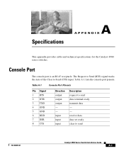
... send 78-18039-02 Catalyst 4900 Series Switch Installation Guide A-1 Table A-1 lists the console port pinouts. receive data data set ready clear to Send (CTS) input. input input input Description request to send data terminal ready transmit data - - Table A-1 Console Port Pinouts Pin Signal 1 RTS 2 DTR 3 TXD 4 GND 5 GND 6 RXD 7 DSR 8 CTS Direction output output output - - Specifications A A P P E N D I X This appendix provides cable and technical specifications for the Catalyst 4900 series switches. Console Port The console port is an RJ-45...
... send 78-18039-02 Catalyst 4900 Series Switch Installation Guide A-1 Table A-1 lists the console port pinouts. receive data data set ready clear to Send (CTS) input. input input input Description request to send data terminal ready transmit data - - Table A-1 Console Port Pinouts Pin Signal 1 RTS 2 DTR 3 TXD 4 GND 5 GND 6 RXD 7 DSR 8 CTS Direction output output output - - Specifications A A P P E N D I X This appendix provides cable and technical specifications for the Catalyst 4900 series switches. Console Port The console port is an RJ-45...
Installation Guide
Page 82
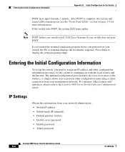
... information). Entering the Initial Configuration Information Appendix B Initial Configuration for the switch to display the setup program prompt. After POST is complete, the system and status LEDs remain green (see the "Front Panel LEDs" section on your management network. Call Cisco Systems if your network administrator: • Switch IP address • Subnet mask (IP netmask) • Default gateway (router) • Enable secret password • Enable password • Telnet password Catalyst 4900 Series Switch Installation Guide B-4 78-18039-02...
... information). Entering the Initial Configuration Information Appendix B Initial Configuration for the switch to display the setup program prompt. After POST is complete, the system and status LEDs remain green (see the "Front Panel LEDs" section on your management network. Call Cisco Systems if your network administrator: • Switch IP address • Subnet mask (IP netmask) • Default gateway (router) • Enable secret password • Enable password • Telnet password Catalyst 4900 Series Switch Installation Guide B-4 78-18039-02...

Installation Guide
Page 83
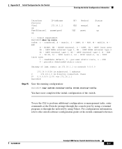
... the initial configuration for the switch: Step 1 Step 2 Step 3 Step 4 Step 5 Step 6 At the terminal prompt, enter the enable command to enter privileged exec mode: Switch> enable Password: password Switch# Set the system time using this command. Tech Support 408 123 4567 c Configure an enable secret password, and press Return. 78-18039-02 Catalyst 4900 Series Switch Installation Guide B-5 To remove the new prompt and return the prompt to its default, use the no prompt command. Switch# clock set location...
... the initial configuration for the switch: Step 1 Step 2 Step 3 Step 4 Step 5 Step 6 At the terminal prompt, enter the enable command to enter privileged exec mode: Switch> enable Password: password Switch# Set the system time using this command. Tech Support 408 123 4567 c Configure an enable secret password, and press Return. 78-18039-02 Catalyst 4900 Series Switch Installation Guide B-5 To remove the new prompt and return the prompt to its default, use the no prompt command. Switch# clock set location...

Installation Guide
Page 84
... suppressed. Switch1 (config)# enable secret SecretPassword Step 9 Configure an enable password, and press Return. hostname Switch1 ! Step 14 Verify the IP information by using the show ip interface brief and show run ! The password can start with a number, is in plain text. Switch1 (config)# enable password EnablePassword Step 10 Configure a virtual terminal (Telnet) password, and press Return. Use an address appropriate for example only. Switch1# show ip interface brief Catalyst 4900 Series Switch Installation Guide B-6 78...
... suppressed. Switch1 (config)# enable secret SecretPassword Step 9 Configure an enable password, and press Return. hostname Switch1 ! Step 14 Verify the IP information by using the show ip interface brief and show run ! The password can start with a number, is in plain text. Switch1 (config)# enable password EnablePassword Step 10 Configure a virtual terminal (Telnet) password, and press Return. Use an address appropriate for example only. Switch1# show ip interface brief Catalyst 4900 Series Switch Installation Guide B-6 78...
Installation Guide
Page 85
... - To use the CLI to the switch software configuration guide or the switch command reference. 78-18039-02 Catalyst 4900 Series Switch Installation Guide B-7 For configuration information, refer to perform additional configuration or management tasks, enter commands at the Switch> prompt through the console port by using a terminal program or through the network by using Telnet. EIGRP, EX - periodic downloaded static route Gateway of last resort is 172.16.1.1 to network 0.0.0.0 172.16.0.0/24 is subnetted, 1 subnets C 172.16.1.0 is directly connected, Vlan1...
... - To use the CLI to the switch software configuration guide or the switch command reference. 78-18039-02 Catalyst 4900 Series Switch Installation Guide B-7 For configuration information, refer to perform additional configuration or management tasks, enter commands at the Switch> prompt through the console port by using a terminal program or through the network by using Telnet. EIGRP, EX - periodic downloaded static route Gateway of last resort is 172.16.1.1 to network 0.0.0.0 172.16.0.0/24 is subnetted, 1 subnets C 172.16.1.0 is directly connected, Vlan1...


