

Installation Guide
Page 7
... N D I X C A P P E N D I X Management Port A-2 Catalyst 4900 Series Switch Specifications A-3 Initial Configuration for the Switch B-1 Connecting to the Switch B-2 Starting the Terminal-Emulation Software B-3 Connecting to a Power Source B-3 Entering the Initial Configuration Information B-4 IP Settings B-4 Performing the Initial Configuration B-5 Compliance Information and Translated Safety Warnings C-1 Translated Safety Warnings C-2 Statement 1003-DC Power ... Notice for Canada C-47 Statement 340-Class A Warning for CISPR22 C-47 78-18039-02 Catalyst 4900 Series Switch Installation Guide vii
... N D I X C A P P E N D I X Management Port A-2 Catalyst 4900 Series Switch Specifications A-3 Initial Configuration for the Switch B-1 Connecting to the Switch B-2 Starting the Terminal-Emulation Software B-3 Connecting to a Power Source B-3 Entering the Initial Configuration Information B-4 IP Settings B-4 Performing the Initial Configuration B-5 Compliance Information and Translated Safety Warnings C-1 Translated Safety Warnings C-2 Statement 1003-DC Power ... Notice for Canada C-47 Statement 340-Class A Warning for CISPR22 C-47 78-18039-02 Catalyst 4900 Series Switch Installation Guide vii
Installation Guide
Page 10
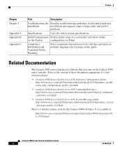
... for your software release: • Catalyst 4500 Series Switch Cisco IOS Software Configuration Guide http://www.cisco.com/en/US/products/hw/switches/ps4324/products_install ation_and_configuration_guides_list.html • Catalyst 4500 Series Switch Cisco IOS Command Reference http://www.cisco.com/en/US/products/hw/switches/ps4324/prod_command _reference_list.html • Catalyst 4500 Series Switch Cisco IOS System Message Guide http://www.cisco.com/en/US/products/hw...
... for your software release: • Catalyst 4500 Series Switch Cisco IOS Software Configuration Guide http://www.cisco.com/en/US/products/hw/switches/ps4324/products_install ation_and_configuration_guides_list.html • Catalyst 4500 Series Switch Cisco IOS Command Reference http://www.cisco.com/en/US/products/hw/switches/ps4324/prod_command _reference_list.html • Catalyst 4500 Series Switch Cisco IOS System Message Guide http://www.cisco.com/en/US/products/hw...

Installation Guide
Page 24
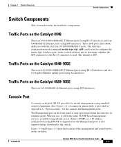
... two 10-Gigabit Ethernet uplink ports. Figure 1-2 Catalyst 4948-10GE Switch 130083 PS1 PS2 FAN STATUS 1 16 17 32 33 Catalyst WS-C4948 10GE X2-1 X2-2 CON 48 MGT The Catalyst 4948-10GE switch has a 136-Gbps, nonblocking, full-duplex switching fabric, providing 102 million packets-per -second of switching capacity for applications where space is limited. Catalyst 4900 Series Switch Installation Guide...
... two 10-Gigabit Ethernet uplink ports. Figure 1-2 Catalyst 4948-10GE Switch 130083 PS1 PS2 FAN STATUS 1 16 17 32 33 Catalyst WS-C4948 10GE X2-1 X2-2 CON 48 MGT The Catalyst 4948-10GE switch has a 136-Gbps, nonblocking, full-duplex switching fabric, providing 102 million packets-per -second of switching capacity for applications where space is limited. Catalyst 4900 Series Switch Installation Guide...
Installation Guide
Page 29
.... The default is in the switch software and to the switch. Console Port A console serial port (RJ-45) provides for these ports in rommon mode. The interface configuration mode command media-type sfp | rj45 can be used . The Management port on the Catalyst 4928-10GE There are 48 10/100/1000BASE-T Ethernet ports using RJ-45 interfaces...
.... The default is in the switch software and to the switch. Console Port A console serial port (RJ-45) provides for these ports in rommon mode. The interface configuration mode command media-type sfp | rj45 can be used . The Management port on the Catalyst 4928-10GE There are 48 10/100/1000BASE-T Ethernet ports using RJ-45 interfaces...

Installation Guide
Page 32
...or a power supply has failed CON MGT Port 1-48 Off Green Off Green Off Green Yellow Flashing yellow Off Switch is disabled 10/100 BASE-T console port is in link-up state 10/100 BASE-T console port is in link-down state or not connected There are no blinking, red, or ...state 10/100 BASE-T Management port is in link-down state or not connected There are no blinking, red, or yellow states for this port Port is operational Port is disabled by user Power-on self-test indicates faulty port No signal detected or link configuration failure 1-10 Catalyst 4900 Series Switch Installation Guide 78...
...or a power supply has failed CON MGT Port 1-48 Off Green Off Green Off Green Yellow Flashing yellow Off Switch is disabled 10/100 BASE-T console port is in link-up state 10/100 BASE-T console port is in link-down state or not connected There are no blinking, red, or ...state 10/100 BASE-T Management port is in link-down state or not connected There are no blinking, red, or yellow states for this port Port is operational Port is disabled by user Power-on self-test indicates faulty port No signal detected or link configuration failure 1-10 Catalyst 4900 Series Switch Installation Guide 78...

Installation Guide
Page 35
If only one power supply plugged in this configuration. Environmental Monitoring of the Power Supplies Using the environmental monitoring and reporting functions, you always connect both power supplies to separate AC or ... conditions prior to loss of the power supply and reports status through software. 78-18039-02 Catalyst 4900 Series Switch Installation Guide 1-13 Chapter 1 Product Overview Figure 1-9 On/Off Switch Locations On/Off Switch Switch Components 113143 The switch will start with only one power supply will not be available in , but redundant failover and...
If only one power supply plugged in this configuration. Environmental Monitoring of the Power Supplies Using the environmental monitoring and reporting functions, you always connect both power supplies to separate AC or ... conditions prior to loss of the power supply and reports status through software. 78-18039-02 Catalyst 4900 Series Switch Installation Guide 1-13 Chapter 1 Product Overview Figure 1-9 On/Off Switch Locations On/Off Switch Switch Components 113143 The switch will start with only one power supply will not be available in , but redundant failover and...

Installation Guide
Page 38
... ensure normal operation and avoid unnecessary maintenance, plan your site configuration and prepare your site. Appendix A, "Specifications," lists the operating and nonoperating environmental site requirements for the switch. Verify your site power before they exceed the maximum operating ...ports of the following sections: • Pre-installation Requirements, page 2-3 • Warnings and Cautions, page 2-3 Catalyst 4900 Series Switch Installation Guide 2-2 78-18039-02 The environmental ranges listed in a rack with little or no clearance above and below the chassis...
... ensure normal operation and avoid unnecessary maintenance, plan your site configuration and prepare your site. Appendix A, "Specifications," lists the operating and nonoperating environmental site requirements for the switch. Verify your site power before they exceed the maximum operating ...ports of the following sections: • Pre-installation Requirements, page 2-3 • Warnings and Cautions, page 2-3 Catalyst 4900 Series Switch Installation Guide 2-2 78-18039-02 The environmental ranges listed in a rack with little or no clearance above and below the chassis...
Installation Guide
Page 53
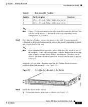
..., depending on the configuration of the rack. Note Some equipment racks provide a power strip along the length of one of the switch to the rack. Position the chassis in the rack as follows (see Figure 3-3): 78-18039-02 Catalyst 4900 Series Switch Installation Guide 3-7 Attach the left...17 32 33 Catalyst WS-C4948 10GE X2-1 X2-2 CON 48 MGT Step 3 Install the chassis in the rack as : a. Chapter 3 Installing the Switch Rack-Mounting the Switch Table 3-1 Quantity 4 4 Rack-Mount Kit Checklist Part Description Received 12-24 x 3/4-inch Phillips binder-head screws 10-32 x ...
..., depending on the configuration of the rack. Note Some equipment racks provide a power strip along the length of one of the switch to the rack. Position the chassis in the rack as follows (see Figure 3-3): 78-18039-02 Catalyst 4900 Series Switch Installation Guide 3-7 Attach the left...17 32 33 Catalyst WS-C4948 10GE X2-1 X2-2 CON 48 MGT Step 3 Install the chassis in the rack as : a. Chapter 3 Installing the Switch Rack-Mounting the Switch Table 3-1 Quantity 4 4 Rack-Mount Kit Checklist Part Description Received 12-24 x 3/4-inch Phillips binder-head screws 10-32 x ...

Installation Guide
Page 61
...instructions for Ethernet connections. The default is used to configure the media type for these switches are laser optical transceivers used for installing SFP modules and X2 modules, which are provided. The interface configuration mode ...cisco.com/en/US/products/hw/modules/ps5455/products_device_sup port_tables_list.html SFP Modules and Alternative Wiring The Catalyst 4948 switches have four ports that can be configured ...with any combination of SFP modules with LC connectors, as shown in the switch software...
...instructions for Ethernet connections. The default is used to configure the media type for these switches are laser optical transceivers used for installing SFP modules and X2 modules, which are provided. The interface configuration mode ...cisco.com/en/US/products/hw/modules/ps5455/products_device_sup port_tables_list.html SFP Modules and Alternative Wiring The Catalyst 4948 switches have four ports that can be configured ...with any combination of SFP modules with LC connectors, as shown in the switch software...

Installation Guide
Page 69
...included because they also monitor DC-line voltages. Note For configuration questions or problems, refer to help isolate the cause. 5 C H A P T E R Troubleshooting the Installation This chapter describes how to troubleshoot the switch hardware installation and contains these sections: • Getting ...has problems starting up, use the information in this chapter to the software configuration guide or the command reference publication. 78-18039-02 Catalyst 4900 Series Switch Installation Guide 5-1 Although temperature conditions above the maximum acceptable level rarely occur at initial ...
...included because they also monitor DC-line voltages. Note For configuration questions or problems, refer to help isolate the cause. 5 C H A P T E R Troubleshooting the Installation This chapter describes how to troubleshoot the switch hardware installation and contains these sections: • Getting ...has problems starting up, use the information in this chapter to the software configuration guide or the command reference publication. 78-18039-02 Catalyst 4900 Series Switch Installation Guide 5-1 Although temperature conditions above the maximum acceptable level rarely occur at initial ...

Installation Guide
Page 70
... Configuration Guide and the Command Reference publications to a single component, it is operating. Usually, it continues to operate even when the environmental monitor shuts down the system because of these conditions are supplying power to what it should be doing. There are not met, use the procedures in the system. Catalyst 4900 Series Switch...
... Configuration Guide and the Command Reference publications to a single component, it is operating. Usually, it continues to operate even when the environmental monitor shuts down the system because of these conditions are supplying power to what it should be doing. There are not met, use the procedures in the system. Catalyst 4900 Series Switch...

Installation Guide
Page 72
... to illuminate red. If the system software is greater than -38.25 +/-2.25V. AC input voltage is less than 82 +/-3V. Catalyst 4900 Series Switch Installation Guide 5-4 78-18039-02 This LED should turn green immediately when power is turned off. DC output voltages are lit: • The ... Off OUTPUT OK Green Meaning This LED should turn green immediately when power is applied to the supply and the power switch is operational (online). In a dual power supply configuration (alternate unit powered) the AC input is less than 33 +/-3V, or the power supply is turned off . ...
... to illuminate red. If the system software is greater than -38.25 +/-2.25V. AC input voltage is less than 82 +/-3V. Catalyst 4900 Series Switch Installation Guide 5-4 78-18039-02 This LED should turn green immediately when power is turned off. DC output voltages are lit: • The ... Off OUTPUT OK Green Meaning This LED should turn green immediately when power is applied to the supply and the power switch is operational (online). In a dual power supply configuration (alternate unit powered) the AC input is less than 33 +/-3V, or the power supply is turned off . ...

Installation Guide
Page 79
Connecting to other Ethernet devices. 78-18039-02 Catalyst 4900 Series Switch Installation Guide B-1 Note You need to provide the Category 5 straight-through cables to connect the switch ports to a Power Source, page B-3 4. Entering the Initial Configuration Information, page B-4 Note If you are using a DC power supply, see the "Connecting DC Power to the Switch, page B-2 2. Connecting to...
Connecting to other Ethernet devices. 78-18039-02 Catalyst 4900 Series Switch Installation Guide B-1 Note You need to provide the Category 5 straight-through cables to connect the switch ports to a Power Source, page B-3 4. Entering the Initial Configuration Information, page B-4 Note If you are using a DC power supply, see the "Connecting DC Power to the Switch, page B-2 2. Connecting to...

Installation Guide
Page 80
...female DTE of the switch, as shown in Figure B-1. Figure B-1 Connecting a Switch to a PC 1 PS1 PS2 FAN STATUS 1 16 17 32 33 Catalyst 4948 CON 48 MGT 45 46 47 48 3 2 181874 1 Switch 2 Laptop 3 RJ-45-to-DB-9 adapter cable Catalyst 4900 Series Switch Installation Guide B-2 78-18039-02... attach an appropriate adapter to the terminal. To connect the switch console port to a PC, use the console port to perform the initial configuration. Connecting to the Switch Appendix B Initial Configuration for the Switch Connecting to the Switch You must use the supplied RJ-45-to-DB-9 adapter ...
...female DTE of the switch, as shown in Figure B-1. Figure B-1 Connecting a Switch to a PC 1 PS1 PS2 FAN STATUS 1 16 17 32 33 Catalyst 4948 CON 48 MGT 45 46 47 48 3 2 181874 1 Switch 2 Laptop 3 RJ-45-to-DB-9 adapter cable Catalyst 4900 Series Switch Installation Guide B-2 78-18039-02... attach an appropriate adapter to the terminal. To connect the switch console port to a PC, use the console port to perform the initial configuration. Connecting to the Switch Appendix B Initial Configuration for the Switch Connecting to the Switch You must use the supplied RJ-45-to-DB-9 adapter ...

Installation Guide
Page 81
...such as Hyperterminal or ProcommPlus-makes communication between the switch and your PC or terminal possible. Catalyst 4900 Series Switch Installation Guide B-3 Appendix B Initial Configuration for instructions on how to install the DC power supply. 78-18039-02 As the switch powers on, it begins the POST, a series...the Terminal-Emulation Software Before you can see the output display from the power-on the switch, start the terminal-emulation session so that the switch functions properly. Configure the baud rate and character format of the power cable to ensure that you power on...
...such as Hyperterminal or ProcommPlus-makes communication between the switch and your PC or terminal possible. Catalyst 4900 Series Switch Installation Guide B-3 Appendix B Initial Configuration for instructions on how to install the DC power supply. 78-18039-02 As the switch powers on, it begins the POST, a series...the Terminal-Emulation Software Before you can see the output display from the power-on the switch, start the terminal-emulation session so that the switch functions properly. Configure the baud rate and character format of the power cable to ensure that you power on...
Installation Guide
Page 82
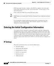
...Cisco Systems if your network administrator: • Switch IP address • Subnet mask (IP netmask) • Default gateway (router) • Enable secret password • Enable password • Telnet password Catalyst 4900 Series Switch Installation Guide B-4 78-18039-02 IP Settings Obtain this information from your switch...Internet. Note POST failures are usually fatal. If the switch fails POST, the system LED turns amber. Press Enter to the Catalyst 4500 Series Switch Software Configuration Guide. The minimal configuration provided here does not cover most of the features, ...
...Cisco Systems if your network administrator: • Switch IP address • Subnet mask (IP netmask) • Default gateway (router) • Enable secret password • Enable password • Telnet password Catalyst 4900 Series Switch Installation Guide B-4 78-18039-02 IP Settings Obtain this information from your switch...Internet. Note POST failures are usually fatal. If the switch fails POST, the system LED turns amber. Press Enter to the Catalyst 4500 Series Switch Software Configuration Guide. The minimal configuration provided here does not cover most of the features, ...

Installation Guide
Page 83
... CNTL/Z. To remove the new prompt and return the prompt to enter global configuration mode. Tech Support 408 123 4567 c Configure an enable secret password, and press Return. 78-18039-02 Catalyst 4900 Series Switch Installation Guide B-5 Switch (config)# Configure a host name for the switch, and press Return. Switch1(config)# banner motd c 170 West Tasman Drive, San Jose...
... CNTL/Z. To remove the new prompt and return the prompt to enter global configuration mode. Tech Support 408 123 4567 c Configure an enable secret password, and press Return. 78-18039-02 Catalyst 4900 Series Switch Installation Guide B-5 Switch (config)# Configure a host name for the switch, and press Return. Switch1(config)# banner motd c 170 West Tasman Drive, San Jose...

Installation Guide
Page 84
...Catalyst 4900 Series Switch Installation Guide B-6 78-18039-02 Step 14 Verify the IP information by using the show ip interface brief and show ip route commands. The password can be from 1 to 25 alphanumeric characters, can be from global configuration mode: Switch (config)# exit Switch # Step 13 View the configuration... password EnablePassword Step 10 Configure a virtual terminal (Telnet) password, and press Return. banner motd ^C 170 West Tasman Drive, San Jose, CA ^C ! !--- Entering the Initial Configuration Information Appendix B Initial Configuration for example only....
...Catalyst 4900 Series Switch Installation Guide B-6 78-18039-02 Step 14 Verify the IP information by using the show ip interface brief and show ip route commands. The password can be from 1 to 25 alphanumeric characters, can be from global configuration mode: Switch (config)# exit Switch # Step 13 View the configuration... password EnablePassword Step 10 Configure a virtual terminal (Telnet) password, and press Return. banner motd ^C 170 West Tasman Drive, San Jose, CA ^C ! !--- Entering the Initial Configuration Information Appendix B Initial Configuration for example only....
Installation Guide
Page 85
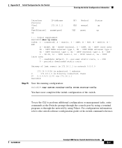
... OK? Switch1# show ip route Codes: C - OSPF, IA - OSPF inter area N1 - OSPF external type 1, E2 - ISIS level-2, ia - per-user static route, o - ODR P - For configuration information, refer to the switch software configuration guide or the switch command reference. 78-18039-02 Catalyst 4900 Series Switch Installation Guide B-7
... OK? Switch1# show ip route Codes: C - OSPF, IA - OSPF inter area N1 - OSPF external type 1, E2 - ISIS level-2, ia - per-user static route, o - ODR P - For configuration information, refer to the switch software configuration guide or the switch command reference. 78-18039-02 Catalyst 4900 Series Switch Installation Guide B-7

Installation Guide
Page 86
Entering the Initial Configuration Information Appendix B Initial Configuration for the Switch Catalyst 4900 Series Switch Installation Guide B-8 78-18039-02
Entering the Initial Configuration Information Appendix B Initial Configuration for the Switch Catalyst 4900 Series Switch Installation Guide B-8 78-18039-02


