

Installation Guide
Page 24
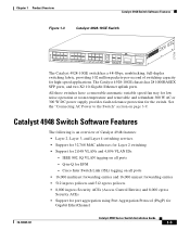
... switching applications. The Catalyst 4948-10GE chassis has 48 10/100/1000BASE-T Ethernet ports and two 10-Gigabit Ethernet uplink ports. The Catalyst 4948 chassis has 44 10BASE-T/100BASE-TX/1000BASE-T Ethernet ports and four ports that can be either 1000BASE-X SFP ports or 10BASE-T/100BASE-TX/1000BASE-T Ethernet ports. Catalyst 4900 Series Switch Applications Chapter 1 Product Overview Catalyst 4900 Series Switch Applications The Catalyst...
... switching applications. The Catalyst 4948-10GE chassis has 48 10/100/1000BASE-T Ethernet ports and two 10-Gigabit Ethernet uplink ports. The Catalyst 4948 chassis has 44 10BASE-T/100BASE-TX/1000BASE-T Ethernet ports and four ports that can be either 1000BASE-X SFP ports or 10BASE-T/100BASE-TX/1000BASE-T Ethernet ports. Catalyst 4900 Series Switch Applications Chapter 1 Product Overview Catalyst 4900 Series Switch Applications The Catalyst...
Installation Guide
Page 25
...; Support for port aggregation using Port Aggregation Protocol (PAgP) for Gigabit EtherChannel 78-18039-02 Catalyst 4900 Series Switch Installation Guide 1-3 Chapter 1 Product Overview Catalyst 4948 Switch Software Features Figure 1-3 Catalyst 4928-10GE Switch 271710 PS1 PS2 FAN STATUS 1 8 9 16 17 CON MGMT... fault-tolerance protection for EFM - Cisco Inter Switch Link (ISL) tagging on page 3-9. The Catalyst 4928-10GE chassis has 28 1000BASEX SFP ports, and two X2 10-Gigabit Ethernet uplink ports. See the "Connecting AC Power to the Switch" section on all ports - Q-...
...; Support for port aggregation using Port Aggregation Protocol (PAgP) for Gigabit EtherChannel 78-18039-02 Catalyst 4900 Series Switch Installation Guide 1-3 Chapter 1 Product Overview Catalyst 4948 Switch Software Features Figure 1-3 Catalyst 4928-10GE Switch 271710 PS1 PS2 FAN STATUS 1 8 9 16 17 CON MGMT... fault-tolerance protection for EFM - Cisco Inter Switch Link (ISL) tagging on page 3-9. The Catalyst 4928-10GE chassis has 28 1000BASEX SFP ports, and two X2 10-Gigabit Ethernet uplink ports. See the "Connecting AC Power to the Switch" section on all ports - Q-...
Installation Guide
Page 28
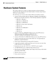
... the last four 10BASE-T/100BASE-TX/1000BASE-T Ethernet ports.) • (Catalyst 4928-10GE) 28 1000BASE-X Ethernet ports using SFP interfaces • (Catalyst 4948-10GE and Catalyst 4928-10GE) Two 10-Gigabit Ethernet uplink ports using X2 interfaces • Serial console management port using RJ-45 interfaces. The following is an overview of switches using Catalyst 4500 series system software. IEEE 802.1Q...
... the last four 10BASE-T/100BASE-TX/1000BASE-T Ethernet ports.) • (Catalyst 4928-10GE) 28 1000BASE-X Ethernet ports using SFP interfaces • (Catalyst 4948-10GE and Catalyst 4928-10GE) Two 10-Gigabit Ethernet uplink ports using X2 interfaces • Serial console management port using RJ-45 interfaces. The following is an overview of switches using Catalyst 4500 series system software. IEEE 802.1Q...
Installation Guide
Page 29
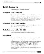
... is used to the switch. Traffic Ports on the Catalyst 4948-10GE There are 48 10/100/1000BASE-T Ethernet ports using RJ-45 interfaces and two 10-Gigabit Ethernet uplink ports using SFP interfaces. The Management port on the Catalyst 4928-10GE There are 48 10/100/1000BASE-T Ethernet ports using RJ-45 interfaces and four 1000BASE-X Ethernet ports using BOOTP is...
... is used to the switch. Traffic Ports on the Catalyst 4948-10GE There are 48 10/100/1000BASE-T Ethernet ports using RJ-45 interfaces and two 10-Gigabit Ethernet uplink ports using SFP interfaces. The Management port on the Catalyst 4928-10GE There are 48 10/100/1000BASE-T Ethernet ports using RJ-45 interfaces and four 1000BASE-X Ethernet ports using BOOTP is...

Installation Guide
Page 32
... mode or a power supply has failed CON MGT Port 1-48 Off Green Off Green Off Green Yellow Flashing yellow Off Switch is disabled 10/100 BASE-T console port is in link-up state 10/100 BASE-T console port is in link-down state or not connected There are no blinking, red, or yellow... for this port Port is operational Port is disabled by user Power-on self-test indicates faulty port No signal detected or link configuration failure 1-10 Catalyst 4900 Series Switch Installation Guide 78-18039-02 Switch Components Chapter 1 Product Overview Table 1-1 describes LED functions.
... mode or a power supply has failed CON MGT Port 1-48 Off Green Off Green Off Green Yellow Flashing yellow Off Switch is disabled 10/100 BASE-T console port is in link-up state 10/100 BASE-T console port is in link-down state or not connected There are no blinking, red, or yellow... for this port Port is operational Port is disabled by user Power-on self-test indicates faulty port No signal detected or link configuration failure 1-10 Catalyst 4900 Series Switch Installation Guide 78-18039-02 Switch Components Chapter 1 Product Overview Table 1-1 describes LED functions.

Installation Guide
Page 42
...= 8.2 ft (2.5 m) 250 VAC, 10 A IRAM 2073 (was CAB-7KACR=) South Africa, CAB-BS546-C15-SA= India (was CAB-7KACSA=) 8.2 ft (2.5 m) 250 VAC, 10 A BS 546 203795 Grounding Requirements Grounding is recommended on the right side of the chassis, and either one may be used. (See Figure 2-1.) Catalyst 4900 Series Switch Installation Guide 2-6 78-18039...
...= 8.2 ft (2.5 m) 250 VAC, 10 A IRAM 2073 (was CAB-7KACR=) South Africa, CAB-BS546-C15-SA= India (was CAB-7KACSA=) 8.2 ft (2.5 m) 250 VAC, 10 A BS 546 203795 Grounding Requirements Grounding is recommended on the right side of the chassis, and either one may be used. (See Figure 2-1.) Catalyst 4900 Series Switch Installation Guide 2-6 78-18039...

Installation Guide
Page 45
... perform any internal components, always use an ESD-preventive wrist or ankle strap, and ensure that you should be between 1 and 10 megohms (Mohms). • Handle cards by the edges only. • Avoid contact between the modules and clothing. Completing each activity...Never assume that power has been disconnected from ESD voltages on the body; Follow these guidelines to ensure a successful switch installation. 78-18039-02 Catalyst 4900 Series Switch Installation Guide 2-9 ESD voltages on the chassis or equipment rack Caution Periodically check the resistance value of the following:...
... perform any internal components, always use an ESD-preventive wrist or ankle strap, and ensure that you should be between 1 and 10 megohms (Mohms). • Handle cards by the edges only. • Avoid contact between the modules and clothing. Completing each activity...Never assume that power has been disconnected from ESD voltages on the body; Follow these guidelines to ensure a successful switch installation. 78-18039-02 Catalyst 4900 Series Switch Installation Guide 2-9 ESD voltages on the chassis or equipment rack Caution Periodically check the resistance value of the following:...

Installation Guide
Page 46
... 5 Cable and interface equipment evaluation: Cable type Connector type Cable distance limitations Interface equipment (transceivers) 6 EMI evaluation: Distance limitations for signaling Site wiring RFI levels 2-10 Catalyst 4900 Series Switch Installation Guide 78-18039-02 Site Planning Checklist Chapter 2 Site Planning Table 2-2 Site Planning Checklist Task No.
... 5 Cable and interface equipment evaluation: Cable type Connector type Cable distance limitations Interface equipment (transceivers) 6 EMI evaluation: Distance limitations for signaling Site wiring RFI levels 2-10 Catalyst 4900 Series Switch Installation Guide 78-18039-02 Site Planning Checklist Chapter 2 Site Planning Table 2-2 Site Planning Checklist Task No.
Installation Guide
Page 53
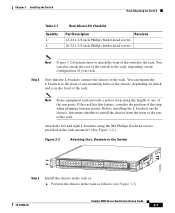
... in the rack as follows (see Figure 3-3): 78-18039-02 Catalyst 4900 Series Switch Installation Guide 3-7 Step 2 Note that the L brackets connect the chassis to the Switch 130086 PS1 PS2 FAN STATUS 1 16 17 32 33 Catalyst WS-C4948 10GE X2-1 X2-2 CON 48 MGT Step 3 Install... the chassis in the rack as : a. Chapter 3 Installing the Switch Rack-Mounting the Switch Table 3-1 Quantity 4 4 Rack-Mount Kit Checklist Part Description Received 12-24 x 3/4-inch Phillips binder-head screws 10-32 x 3/4-inch ...
... in the rack as follows (see Figure 3-3): 78-18039-02 Catalyst 4900 Series Switch Installation Guide 3-7 Step 2 Note that the L brackets connect the chassis to the Switch 130086 PS1 PS2 FAN STATUS 1 16 17 32 33 Catalyst WS-C4948 10GE X2-1 X2-2 CON 48 MGT Step 3 Install... the chassis in the rack as : a. Chapter 3 Installing the Switch Rack-Mounting the Switch Table 3-1 Quantity 4 4 Rack-Mount Kit Checklist Part Description Received 12-24 x 3/4-inch Phillips binder-head screws 10-32 x 3/4-inch ...

Installation Guide
Page 56
... Supply On/off while the power supply is plugged in, or the power supply may be defective and not providing DC power to the switch. The on/off switch may also be a fan failure. • The PS1 or PS2 LED is off when there is green when the power supply and fans.... Verify power supply operation by looking at the front panel power supply LEDs: • The PS1 or PS2 LED is no power supply installed. 3-10 Catalyst 4900 Series Switch Installation Guide 78-18039-02 There may be used, make sure they are functioning normally. • The PS1 or PS2 LED is red when...
... Supply On/off while the power supply is plugged in, or the power supply may be defective and not providing DC power to the switch. The on/off switch may also be a fan failure. • The PS1 or PS2 LED is off when there is green when the power supply and fans.... Verify power supply operation by looking at the front panel power supply LEDs: • The PS1 or PS2 LED is no power supply installed. 3-10 Catalyst 4900 Series Switch Installation Guide 78-18039-02 There may be used, make sure they are functioning normally. • The PS1 or PS2 LED is red when...

Installation Guide
Page 58
... screwdriver. Connect the power supply ground terminal to AWG #12 wire. 3-12 Catalyst 4900 Series Switch Installation Guide 78-18039-02 Note The DC power cables may use AWG #10 to earth ground. Connecting DC Power to the Switch Chapter 3 Installing the Switch Step 1 Step 2 Step 3 Prior to connecting the power supply to a power source...
... screwdriver. Connect the power supply ground terminal to AWG #12 wire. 3-12 Catalyst 4900 Series Switch Installation Guide 78-18039-02 Note The DC power cables may use AWG #10 to earth ground. Connecting DC Power to the Switch Chapter 3 Installing the Switch Step 1 Step 2 Step 3 Prior to connecting the power supply to a power source...

Installation Guide
Page 62
More general installation information is in Figure 4-2 and Figure 4-3. Figure 4-1 Connecting LC Connectors to the 10-Gigabit Ethernet Transceiver Modules Compatibility Matrix at the following location: http://www.cisco.com/en/US/products/hw/modules/ps5455/products_device_sup port_table09186a00803857e7.html Catalyst 4900 Series Switch Installation Guide 4-2 78-18039-02 X2 Modules Chapter 4 Transceiver Modules Note You must connect...
More general installation information is in Figure 4-2 and Figure 4-3. Figure 4-1 Connecting LC Connectors to the 10-Gigabit Ethernet Transceiver Modules Compatibility Matrix at the following location: http://www.cisco.com/en/US/products/hw/modules/ps5455/products_device_sup port_table09186a00803857e7.html Catalyst 4900 Series Switch Installation Guide 4-2 78-18039-02 X2 Modules Chapter 4 Transceiver Modules Note You must connect...

Installation Guide
Page 64
For either the top or bottom connector, forcing a module could potentially damage both the module and the switch. Catalyst 4900 Series Switch Installation Guide 4-4 78-18039-02 X2 Modules Chapter 4 Transceiver Modules Figure 4-3 Installing the 10-Gigabit Ethernet X2 Module Catalyst WS-C4948 10GE CON X1 MGT LINK X2 Catalyst WS-C4948 10GE CON X1 MGT X2 130091 Caution If you attempt to insert the bottom X2 module with the cooling fins pointing up, you will probably permanently damage the connector.
For either the top or bottom connector, forcing a module could potentially damage both the module and the switch. Catalyst 4900 Series Switch Installation Guide 4-4 78-18039-02 X2 Modules Chapter 4 Transceiver Modules Figure 4-3 Installing the 10-Gigabit Ethernet X2 Module Catalyst WS-C4948 10GE CON X1 MGT LINK X2 Catalyst WS-C4948 10GE CON X1 MGT X2 130091 Caution If you attempt to insert the bottom X2 module with the cooling fins pointing up, you will probably permanently damage the connector.

Installation Guide
Page 76
... 0 Bidirectional data pair 0 Bidirectional data pair 1 Bidirectional data pair 2 Bidirectional data pair 2 Bidirectional data pair 1 Bidirectional data pair 3 Bidirectional data pair 3 Catalyst 4900 Series Switch Installation Guide A-2 78-18039-02 Table A-2 10/100BASE-T Port Pinouts Pin Signal 1 RXDP 2 RXDN 3 TXDP 4 unused 5 unused 6 TXDN 7 unused 8 unused Direction input input output - - output - - Table A-2 lists the...
... 0 Bidirectional data pair 0 Bidirectional data pair 1 Bidirectional data pair 2 Bidirectional data pair 2 Bidirectional data pair 1 Bidirectional data pair 3 Bidirectional data pair 3 Catalyst 4900 Series Switch Installation Guide A-2 78-18039-02 Table A-2 10/100BASE-T Port Pinouts Pin Signal 1 RXDP 2 RXDN 3 TXDP 4 unused 5 unused 6 TXDN 7 unused 8 unused Direction input input output - - output - - Table A-2 lists the...
Installation Guide
Page 77
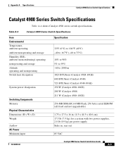
... dissipation Switching Components Memory Physical Characteristics Dimensions (H x W x D) Weight Airflow AC Power Minimum input Specification 32°F (0°C) to 104°F (40°C) -40 to 167°F (-40 to 75°C) 10% to 90% 5% to 95% -60 to 2000 m 1023 BTU/hour (Catalyst 4928-10GE) 600 BTU/hour (Catalyst 4948) 723 BTU/hour (Catalyst 4948-10GE) 150 W (Catalyst 4928...
... dissipation Switching Components Memory Physical Characteristics Dimensions (H x W x D) Weight Airflow AC Power Minimum input Specification 32°F (0°C) to 104°F (40°C) -40 to 167°F (-40 to 75°C) 10% to 90% 5% to 95% -60 to 2000 m 1023 BTU/hour (Catalyst 4928-10GE) 600 BTU/hour (Catalyst 4948) 723 BTU/hour (Catalyst 4948-10GE) 150 W (Catalyst 4928...

Installation Guide
Page 84
...password can start with a number, is case sensitive, allows spaces, but ignores leading spaces. Switch1# show ip interface brief Catalyst 4900 Series Switch Installation Guide B-6 78-18039-02 Step 14 Verify the IP information by using the show ip interface brief and show ip... you want. Switch1 (config)# enable secret SecretPassword Step 9 Configure an enable password, and press Return. Switch1 (config)# enable password EnablePassword Step 10 Configure a virtual terminal (Telnet) password, and press Return. banner motd ^C 170 West Tasman Drive, San Jose, CA ^C ! !--- Entering...
...password can start with a number, is case sensitive, allows spaces, but ignores leading spaces. Switch1# show ip interface brief Catalyst 4900 Series Switch Installation Guide B-6 78-18039-02 Step 14 Verify the IP information by using the show ip interface brief and show ip... you want. Switch1 (config)# enable secret SecretPassword Step 9 Configure an enable password, and press Return. Switch1 (config)# enable password EnablePassword Step 10 Configure a virtual terminal (Telnet) password, and press Return. banner motd ^C 170 West Tasman Drive, San Jose, CA ^C ! !--- Entering...

Installation Guide
Page 96
Translated Safety Warnings Appendix C Compliance Information and Translated Safety Warnings • • • • • • C-10 Catalyst 4900 Series Switch Installation Guide 78-18039-02
Translated Safety Warnings Appendix C Compliance Information and Translated Safety Warnings • • • • • • C-10 Catalyst 4900 Series Switch Installation Guide 78-18039-02

Installation Guide
Page 140
... power supply 1-12 heat dissipation determining 2-4 I installation connecting to a power source B-3 IN-2 Catalyst 4900 Series Switch Installation Guide starting the terminal-emulation software B-3 installing the switch guidelines 3-2 lifting 3-5 procedure 3-6 safety overview 2-7 tools required 3-5 troubleshooting 5-1 L label, chassis serial number 5-6 LEDs locations 1-9 meanings 1-10 POST results B-4 power supply 5-3 M management port pinout A-2 memory A-3 MT-RJ connectors cleaning...
... power supply 1-12 heat dissipation determining 2-4 I installation connecting to a power source B-3 IN-2 Catalyst 4900 Series Switch Installation Guide starting the terminal-emulation software B-3 installing the switch guidelines 3-2 lifting 3-5 procedure 3-6 safety overview 2-7 tools required 3-5 troubleshooting 5-1 L label, chassis serial number 5-6 LEDs locations 1-9 meanings 1-10 POST results B-4 power supply 5-3 M management port pinout A-2 memory A-3 MT-RJ connectors cleaning...

Installation Guide
Page 141
Index port status LED 1-10 POST LEDs B-4 power connecting 3-9, 3-11 DC grounding requirements 2-6 determining power requirements and heat dissipation 2-4 EMI recommendations 2-4 general ...recommendations 2-4 environmental requirements 2-1 general requirements 2-3 overview 2-1 warnings and cautions 2-3 software documentation i-x specifications AC Power A-3 DC Power A-4 environmental A-3 switching components A-3 startup sequence 5-3 status LED 1-10 system specifications A-1 T temperature thresholds 2-2 terminal-emulation software B-3 Catalyst 4900 Series Switch Installation Guide IN-3
Index port status LED 1-10 POST LEDs B-4 power connecting 3-9, 3-11 DC grounding requirements 2-6 determining power requirements and heat dissipation 2-4 EMI recommendations 2-4 general ...recommendations 2-4 environmental requirements 2-1 general requirements 2-3 overview 2-1 warnings and cautions 2-3 software documentation i-x specifications AC Power A-3 DC Power A-4 environmental A-3 switching components A-3 startup sequence 5-3 status LED 1-10 system specifications A-1 T temperature thresholds 2-2 terminal-emulation software B-3 Catalyst 4900 Series Switch Installation Guide IN-3


